S.p.A
Component for Pneumatic Automation Via Cascina Barbellina, 10 - 24050 LURANO (BG) ITALY - Tel. 035/4192777 - Fax 035/4192740-4192741
SENSORI MAGNETICI - MAGNETIC SENSORS - CAPTEURS MAGNETIQUES - MAGNETSENSOREN - SENSORES MAGNÉTICOS
IMPIEGO: Si utilizzano su cilindri a tiranti, a tubo profilato, micro cilindri, cilindri corsa breve e cilindri senza stelo, tutti dotati di pistone magnetico.
AVVERTENZE: Si ponga particolare attenzione affinchè non vengano superati i pur ampi limiti d’impiego, elencati nella tabella posta sul retro, e che vengano sempre osservati gli accorgimenti
che seguiranno, in modo da non danneggiare i sensori. Si tenga presente che, al momento dell’inserzione del carico, la corrente assorbita dai sensori può essere anche del 50% superiore alla
nominale. Data la particolare struttura a semiconduttori del circuito di commutazione di questi sensori, non esistono controindicazioni d’uso, in quanto è indifferente che il carico supportato sia
induttivo, capacitivo o resistivo.
Nel caso di alimentazione a corrente continua (DC) va rispettata la polarità di collegamento: il filo marrone al positivo (+) ed il filo blu al negativo (-) inoltre va posta attenzione alla lunghezza del
cavo la quale non deve superare i 10m complessivi. Qualora fosse necessario superare la lunghezza prevista si consiglia di inserire una induttanza o una resistenza in serie allo scopo di annullare
la capacità creata dal cavo stesso. Nel caso si utilizzi un sensore Reed a due fili (tipo A,B,D,E,P) accertarsi sempre che vi sia un carico collegato in serie indifferentemente o al filo marrone o al filo
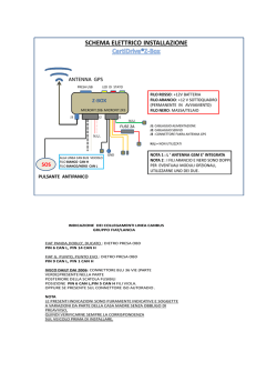
blu. Nella versione con connettore Snap a due pin porre particolare attenzione all’orientamento del connettore stesso (vedi figura 1) invertendo il collegamento, infatti, il
circuito non subisce alcun danno, ma il diodo Led rimarrebbe sempre spento. Collegando due o più sensori in serie occorre tener presente la caduta di tensione (circa 3V
per sensore), ed eventualmente utilizzare la versione dei sensori per il collegamento in serie (Tipo C). I sensori ad effetto di Hall (tipo K,L,M) non avendo organi meccanici in
movimento hanno una vita media notevolmente superiore rispetto ai sensori ad ampolla Reed. Per tutti i modelli di sensore occorre porre particolare attenzione ai fattori
esterni come la vicinanza di cavi sotto tensione, campi magnetici generati da motori elettrici, masse di metallo a conduzione magnetica troppo vicine al sensore, ecc… in
Fig. 1
quanto possono influenzare i sensori e determinare anomalie di funzionamento.
APPLICATION: The magnetic sensors are designed to be used on tie rod cylinders, profile tube cylinders, microcylinders, short stroke compact cylinders and on rodless cylinders with magnetic
piston.
INSTRUCTIONS ON HOW TO PROPERLY USE THE SENSORS: Particular attention should be paid in order not to exceed the wide operating limits shown in the specification table. Besides, the
2 wires sensors have never to be connected to the mains if a load has not been yet connected in series.These are the only cares that, if not followed, may cause damages to the sensor. Furthermore
it has to be considered that, while loading, the current absorbed by the sensors might be 50% higher that the rated one.
The switch semiconductor construction design makes this sensors extremely compatible, there are no limitation to the type of load applied : inductive, capacitive resistive.
In case of direct current (DC) feeding, the polarity of the connection has to be observed: the brown cable must be connected to the plus (+) and the blue one to the minus (-). The cable length must
not exceed 10mtrs. If the cable needs to be longer then 10 mt, we recommend to insert in series an inductance or a resistance to counteract the capacity generated by the cable itself .
When using a two wire REED type sensor (Type A,B,D,E,P,) always ensure that the correct load is applied in series on any of the two wires. When using a sensor fitted with the SNAP connector pay
attention to the orientation of the connector (see fig.1) because by inverting the connection the circuit will not be damaged, but the LED will not turn on. In case of two or
more sensors connected in series pay attention to tension drop generated (around 3V for each sensor), and eventually use the version designed for in series connection
("type C"). The Hall effect sensors, (type K,L,M) which do not include any moving mechanical parts are longer lasting if compared to the Reed version besides, there are
some other external factors to be taken into consideration, such as proximity of powered cables, magnetic fields produced by electric motors, mass of iron too close to the
Fig. 1
sensor, and so on: these factors have to be therefore carefully avoided, being able to influence the sensors and accordingly to cause irregularity of operation.
UTILISATION: Utilisé sur des vérins tube profilé, microvérin, vérin compact et vérin sans tige, tous équipés de piston magnétique.
AVERTISSEMENT: Il est important de faire attention aux conditions d'utilisation et de ne pas dépasser les limites autorisées qui sont indiquées dans le tableau situé au verso et que ces conditions
seront toujours observées dans les applications afin de ne pas détériorer les capteurs magnétiques.
Nous vous rappelons qu'au moment d'insérer la charge, l'intensité absorbée par les capteurs magnétiques peut dépasser de 50% la valeur nominale.
Etant donné la structure particulière des semi conducteurs du circuit de commutation de ces capteurs magnétiques, il n'existe pas de contre indication d'utilisation pour la charge car elle supporte
indifféremment aussi bien de l'inductif, capacitif ou résistif.
Dans le cas d'une alimentation en tension continue (DC) il faudra respecter le polarité au moment du raccordement : le fil marron au positif (+) et le fil bleu au négatif (-) néanmoins il faudra faire
attention à la longueur du câble, laquelle ne doit pas dépasser 10m au total. S'il faut aller au delà de cette longueur, il est conseillé d'insérer une inductance ou une résistance afin d'annuler la
capacité créée par ce câble.
Dans le cas où est utilisé un capteur magnétique Reed à deux fils (type A,B,D,E,P) ) il faudra toujours qu'il y est une charge raccorder en série indifféremment ou au fil
marron ou bleu.
Pour la version avec connecteur Snap à deux pin, il faudra faire attention à l'orientation du connecteur (voir figure 1) en inversant le raccordement, le circuit ne subira aucun
dégât mais la diode Led restera inévitablement éteinte.
Fig. 1
VERWENDUNG: Sie werden eingesetzt für Zylinder mit Profilwandung, Mikrozylinder, Kurzhubzylinder und Zylinder ohne Schubstange, die alle mit Magnetkolben ausgeruestet sind.
ACHTUNG: Die Grenzen der Anwendungsbereiche, aus der Tabelle auf der Rueckseite ersichtlich, sind zwar sehr grosszuegig ausgelegt, sollten aber trotzdem nicht überschritten werden.
Ausserdem sind die nachfolgenden Ausfuehrunger unbedingt zu beherzigen, um die Sensoren nicht zu beschaedigen. Weiter ist zu beach ten, dass der Einschaltstomstoss der Sensoren
u.U.50% hoeher sein kann als der Nennstrom. Da die Schaltkreise dieser Sensoren aus Halbleitern bestehen, kann die Last ohne Unterschied und problemlos entweder induktiv, kapazitiv oder
ohmisch sein. Erfolgt die Stromversorgung mit Gleichstrom (DC), ist auf die Polaritaet des Anschlusses zu achten: der braune Draht geht an plus (+), und der blaue Draht geht an minus (-).
Aussedem muss auf die Kabellaenge geachtet werden, sie sollte insgesamt 10 Meter nicht uebersteigen. Falls sich die Notwendigkeit ergibt, mit groesseren Kabellaengen arbeiten zu muessen,
ist eine Induktivitaet oder ein Widerstand vorzuschaltem, um den durch die Leitungskapazitaet verursachten Einschaltstromstoss zu verringern. Wird ein zweidraehtiger Reedkontakt-Sensor (Typ
A,B,D,E,P) eingesetzt, muss sichergestellt sein, dass eine Last in Reihe mit entweder dem braunen oder dem Blauen Draht eingescleift ist. Bezüglich der Ausführung des zweipoligen
Steckverbinders Snap ist besondere sorgfalt erforderlich, um den Steckverbinder richtig gepolt einzuführen (siehe Figur 1), weil sonst wohl kein Schaden entstehen würde, aber man der
Anzeigefunktion des Schaltzustandes durch die Leuchtdiode verlustig gehen würde. Wenn zwei oder mehr Sensoren in Reihe geschaltet sind, hat man sich des daraus
entstehenden Spannungsabfalls (circa 3V pro Sensor) zu vergegenwaertigen und eventuell die Version für Reihenschaltung (Typ C) einzusetzen. Die sensoren mit
Halleffekt-Schalter (typ K,L,M) haben eine wesentlich hoehere mittler Lebensdauer als die Sensoren mit Reedkontakt, da diese keine beweglichen mechanischen Bauteile
enthalten.
Fuer alle Sensormodelle gilt aeusseren Einfluessen Beachtung zu schenken wie die Naehe zu spannungsfuehrenden Kabeln, von Motoren erzeugten Magnetfeldern, von
Gestal. 1
magnetisch leitenden Massen von Metallen usw. …., da dieselben die Sensoren beeinflussen und so deren normale Funktion beeintraechtigen koennen.
EMPLEO: Se utilizan sobre cilindros de tirantes y de tubo perfilado, microcilindros, cilindros de carrera corta y cilindros sin vástago provistos de pistón magnético.
INSTRUCCIONES PARA UN CORRECTO USO DE LOS SENSORES:
Debe ponerse particular atención a que no sean superados los amplios límites de empleo reseñados en las tablas situadas en la cara posterior y que los sensores a 2 hilos no sea nunca
conexionado a la alimentación a fin de que no sea una carga unida en serie. Estas son las únicas precauciones que deben tomarse para no dañar los sensores. Téngase presente además que, en
el momento de la inserción de la carga, la corriente absorbida puede ser hasta un 50 % superior a la nominal y por tanto, especialmente para la corriente alterna, deben respetarse los oportunos
márgenes de seguridad. En el caso de sensores de corriente continua debe respetarse la polaridad en la conexión : el hilo marrón al positivo (+) y el hilo azul al negativo (-) con la carga unida en
serie. En la versión con conector poner atención a la orientación del mismo (ver figura 1) : invirtiendo la conexión el circuito no sufre daños, pero en fase de conmutación, el led permanece
encendido. Dada la particular estructura por semiconductores del circuito de conmutación de estos sensores, no existen contraindicaciones de uso, siendo indiferente que la carga soportada
sea inductiva, capacitiva o resistiva. Para los sensores del tipo universal (U), en caso de utilizarlos con corriente continua (D.C.) la longitud del cable no debe superar los 10
m. Si la longitud del cable supera los 10 m previstos, se aconseja insertar una resistencia con el fin de anular la propiedad capacitiva creada por el mismo cable. En el caso
de conexionar en serie dos o más sensores es necesario tener en cuenta la caída de tensión (casi 3 V por cada sensor) y ocasionalmente utilizar la versión creada al efecto
(1 L en el código de pedido). Los sensores de efecto Hall, al no tener partes mecánicas en movimiento, tienen una duración notablemente superior respecto a los sensores
con contacto reed, Para todos los modelos de sensores es necesario poner especial atención a factores externos como la cercanía de cables bajo tensión, campos
Fig. 1
magnéticos generados por motores eléctricos, masas de hierro demasiado cercanas al sensor, etc. Ya que pueden influir en los sensores y determinar anomalías de
funcionamiento.
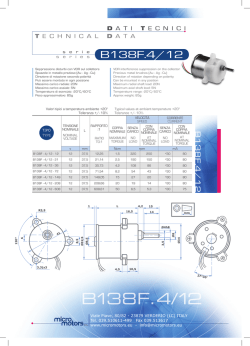
FISSAGGIO (SERIE) - INSTALLATION (SERIES) - FIXATIONS (SÉRIE) - MONTAGE (SERIE) - FIJACIÓN (SERIE)
1200
Alla camicia con fascetta in plastica
To the barrel with plastic clamp
Sur le tube avec un collier plastique
Am Zylinderrohr mit Kunststoffhalter
A la camisa con abrazadera en plástico
1306-7-8
Al tirante con staffa di alluminio
To the rod with alluminium bracket
Sur le tirant avec un support en aluminium
An der Zugstange mit Befestigungsbügel (Alu)
Al tirante con brida en aluminio
1319-20 / 1325 / 1345
1330-32 / 1348-49
Al profilo con staffa di alluminio
To the profile with alluminium bracket
Sur le profil avec un support en aluminium
Am profil mit Befestigungsbügel (Alu)
Al perfil con soporte en aluminio
1500
EUROPE
Nell’ apposita cava con vite
In its groove with fixing screw
Dans la rainure en Te avec la vis
In der T-nut mit Fixierschraube
En el específico canal con tornillo
1600
Al profilo con staffa di alluminio
To the profile with alluminium bracket
Sur le profil avec un support en aluminium
Am Profil mit Befstigungsbügel (Alu)
Al perfil con soporte en aluminio
I dati indicati possono essere soggetti a modifica senza preavviso / Specifications may be subject to change without prior notice / Technische Änderungen vorbehalten / Sous réserves de modifications sans préavis / Los datos indicados pueden ser modificados sin preaviso
1A
0,5A
8VA
10VA
N.O.
N.C.
3
2V
*
1
black
3
5
7
[ PNP ]
4
*
4
brown
blue
black
Sensor type: H-K-M
LOAD
brown
blue
Sensor type: B
2
3
7
[ NPN ]
1
*
blue
brown
black
blue
brown
black
blue
black
brown
Sensor type: C
LOAD
brown
blue
Sensor type: E
4
2
2
1
D.IS.01/IT - 12/2008 (IMB.STR01) / PRINTED IN ITALY 12/2008
1
*
*
*
*
*
~
~
LOAD
brown
blue
Sensor type: P
LOAD
*
brown
blue
Sensor type: D
1
*
2
1
4
3
Tab. 1
Code
P
A
K
J
H
G
B
D
C
Type
Code
1600.AC
1600.DC
1600.HAN
Ø 4,2 mm
1600.HAP
PUR
1600.HCN
2
2 / 3x 0,34 mm 1600.HCP
1600.U
1600.U/1
1600.U/1L
Cable
P
A
K
J
H
G
B
D
C
Type
Cable
Code
SNAP code connectors
Ø 3,5 mm
CH1
PVC
CH2
2
3x 0,25 mm
CH3
HS.NA
HS.PA
HS8.NA
Ø 4,2 mm
HS8.PA
PUR
RS.DC
2
2 / 3x 0,34 mm RS.DCNO
RS.UA
RS.UA/1
SRS.UA/1L
SRS.UC
M8 code connectors
Ø 2,6 mm
MC1
PUR
MC2
2
2x 0,15 mm
MC3
Connettore
Connector
Connecteur
Kabelstecker
Conector
SNAP code connectors
Ø 3,5 mm
C1NO
PVC
C2NO
2
C3NO 2x 0,25 mm
Sensore
Sensor
Capteur
Sensorstecker
Sensor
Connector type 2
(Normally open)
M
L
M
L
A
A
B
D
C
E
3
2
3
3
1
3
2
2
2
2
6W
6÷30V
0,25A
M
NPN
C
D
B
E
A
B
C
B
A
B
2
2
1
2
2
2
3
1
1
2
RS8.UC
SHS.NA
SHS.PA
SHS8.NA
SHS8.PA
SRS.DC
SRS.UA
SRS.UA/1
SRS8.UA/1L
SRS8.UC
Type Connector Code
E
M
L
M
L
A
B
D
C
E
2
2
3
3
3
2
2
2
2
2
Type Connector
Blue (-)
Bleu (-)
blau (-)
Azul (-)
Connettore 1 Marrone (+)
Brown (+)
Connector
Marron (+)
Connecteur
braun (+)
Kabelstecker Marrón (+)
Conector
3 Blu (-)
SNAP code connectors
Ø 3,5 mm
C1
PVC
C2
2
2x 0,25 mm
C3
Sensore
Sensor
Capteur
Sensorstecker
Sensor
Pinatura 2 fili 2 PIN / Connection 2 wires 2 PIN
Raccordement à 2 fils 2 PIN / Anschlüsse 2 polig 2 PIN
Conexión 2 hilos 2 PIN
RS.UA/1L
RS.UA/1NO
RS.UANO
RS.UC
RS8.DC
RS8.UA
RS8.UA/1L
RS8.UANO
SRS8.DC
SRS8.UA
Type Connector Code
M8 code connectors
Ø 2,6 mm
MCH1
PUR
MCH2
2
MCH3 3x 0,15 mm
L
PNP
(Normally open)
± 0,1 mm
109 cicli
Connector type 3
(Normally closed)
Pinatura 3 fili 3 PIN / Connection 3 wires 3 PIN
Raccordement à 3 fils 3 PIN/ Anschlüsse 3 polig 3 PIN
Conexión 3 hilos 3 PIN
1 Marrone (+)
1 Marrone (+)
Sensore
Connettore
Brown (+)
Brown (+)
Marron (+)
Sensor
Connector
Marron (+)
braun (+)
Capteur
Connecteur
braun (+)
Marrón (+)
Sensorstecker Kabelstecker
Marrón (+)
4 Blu (-)
Sensor
Conector
4 Blu (-)
Blue (-)
Blue (-)
Bleu (-)
Bleu (-)
blau (-)
blau (-)
Azul (-)
Azul (-)
3 Nero (segnale)
3 Non utilizzato
Black (signal)
Not used
Noir (signal)
Non Utilisé
Schwarz
nicht belegt
(Signal)
No utilizado
Negro
(señal)
Pinatura 2 fili 3 PIN / Connection 2 wires 3 PIN
Raccordement à 2 fils 3 PIN / Anschlüsse 2 polig 3 PIN
Conexión 2 hilos 3 PIN
Connector type 1
1500.A.C
1500.D.C
Il carico( LOAD) può essere collegato indifferentemente al
1500.HAN
polo positivo o al polo negativo.
The load (LOAD) can be connected either to negative or
1500.HAP
positive pole
La charge (LOAD) peut etre raccorder indifferemment au 1500.HCN
pole positif ou au pole negativ.
1500.HCP
Die Last (LOAD) kann sowohl an den positiven als auch
1500.U
an den negativen Pol angeschlossen werden.
1500.U/1
La carga puede ser conexionada indistintamente al polo
negativo o al positivo.
1500.U/1L
3
[ PNP ]
4
3
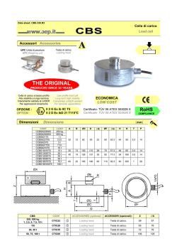
1: Contatto magnetico (REED) - Magnetic contact (REED) - 5: Transistor
Contact magnetique (REED) - Magnetkontakt (REED) - 6: Diodo Zener di protezione - Zener protective diode Diode Zener de protection - Zener schutzdiode Contacto magnético Reed
Diodo Zener de protección
2: Varistore - Varistor
7:
Circuito effetto Hall - Hall effect circuit 3: Diodo luminoso (LED) - Luminous diode (LED) Circuit à effet de Hall - Elektronischer Schultkreis-Hall Diode luminescente (LED) Leuchtdiode (LED) Circuito efecto may
Diodo luminoso LED
4: Resistenza Resistance Resistance
Widerstand Resistencia
blue
LOAD
brown
Sensor type: G-J-L
LOAD
brown
blue
6
LOAD
Sensor type: A
SCHEMI SEMPLIFICATI - SEMPLIFIED DIAGRAM - SCHEMAS SIMPLIFIES - ANSCHLUSSBILD - ESQUEMA
N.C.
(Normally closed)
N.O.
(Normally open)
± 0,1mm
Ripetizione del punto d’ intervento - Repetition of intervention point
Precision de repetitive - Reproduzierbare Schaltgenauigkeit - Repetición del punto de intervención
Tipo di contatto - Type of contact - Contact - Kontakt - Tipo de contacto
1ms
107 cicli
Tempo di disinserzione - Disconnecting time - Temps de coupure - Ausschaltzeit - Tiempo de dexcitación
Durata media di lavoro - Average working period - Duree de vie - Lebensdauer - Duración media de trabajo
blue
blue
N.O.
-20°C/+70°C
10W
15W
0,3μs
3V
300VA
375VA
0,8μs
2
6W
8W
0,5A
D.C.
NPN
2ms
8VA
10VA
10÷30V
0,5A
PNP
HALL EFFECT
K
J
Tempo di inserzione - Connecting time - Temps de fermeture - Einschaltzeit - Tiempo de inserción
0V
6W
8W
12÷250V
6A
1,5A
A.C.
H
NPN
Grado di protezione - Degree of protection - Degre de protection - Schutzart - Grado de protección
3
D.C.
G
PNP
IP 65
2
3V
0,8A
0,3A
A.C.
P
IP 65
Numero cavi - Cables number - Nombre de câbles - Anzahl der Kabel - Número cable
2V
D.C.
E
0÷250V 0÷48V 3÷110V 12÷48V
A.C.
-20°C/+70°C
12W
15VA
12W
15VA
32W
Carico (induttivo) - Load (inductive) - Charge (inductive) - Kraft (ind.) - Carga (inductiva)
Temperatura di esercizio - Working temperature Temperature de service - Betriebstemperatur - Temperatura de ejercicio
Caduta di tensione massima - Maximum voltage drop
Chute de tension maxi - Max. Spannungsabfall - Caída de tensión máxima
15W
20VA
24V
D.C.
15W
A.C.
20VA
3÷250V 12÷48V
D.C.
REED AMPULLA
C
D
32W
12÷30V
A.C.
B
Potenza massima permanente - Maximum permanent power
Puissance maxi permanente - Max. Dauerleistung - Potencia máxima permanente
Campo di tensione - Voltage range - Tension d’ utilisation - Betriebsspannung
Campo de tensión - Campo de tensión
1,5A
1,2A
Corrente max di commutazione (impulsi di 0,5s.) - Maximum swit chover current (0,5 sec.pulse)
Intensité maximum permanente - Max. Dauerstrom - Corriente max. de conmutación (impulsos de 0,5 seg.)
D.C.
Corrente utilizzabile - Usable current - Intensité nominale - Stromart - Corriente utilizada
A
Corrente massima permanente - Maximum permanent current - Intensite maximum permanente
Max. Dauerstrom - Corriente máx. Permanente - Corriente máxima permanente
Tipo sensore (Tab.1) - Sensor type (table 1) - Type capteur (table 1)
Art des Magnetsensors - Tipo sensor (tabla 1)
CARATTERISTICHE TECNICHE - TECHNICAL CHARACTERISTICS - CARACTERISTIQUES TECHNIQUES - TECHNISCHE DATEN - CARACTERÍSTICAS TÉCNICAS
LOAD
© Copyright 2026 Paperzz