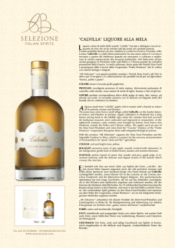
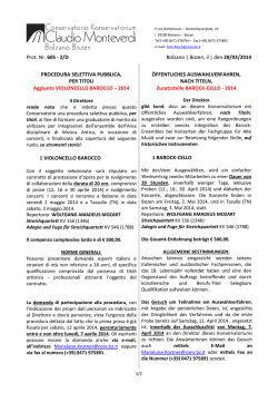
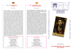
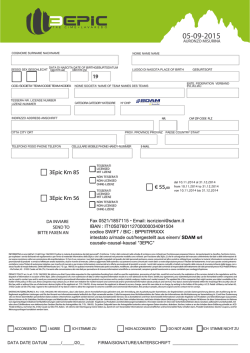
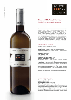
Premium Armaturen + Systeme
D
Heizkessel-Anbindesystem „Regumat“ DN 25
Einbau- und Betriebsanleitung für Fachpersonal
!
Vor dem Einbau des Heizkessel-Anbindesystems
die Einbau- und Betriebsanleitung vollständig
lesen!
Einbau, Inbetriebnahme, Bedienung und Wartung
darf nur durch geschultes Fachpersonal durchgeführt werden!
Die Einbau- und Betriebsanleitung sowie alle mitgeltenden Unterlagen sind an den Anlagenbetreiber
weiterzugeben!
Inhalt
1
2
3
4
5
6
7
8
9
10
Allgemeine Hinweise . . . . . . . . . . . . . . . . . . . 1
Sicherheitshinweise . . . . . . . . . . . . . . . . . . . . 2
Transport, Lagerung und Verpackung . . . . . . 2
Technische Daten . . . . . . . . . . . . . . . . . . . . . 2
Aufbau und Funktion . . . . . . . . . . . . . . . . . . . 5
Einbau . . . . . . . . . . . . . . . . . . . . . . . . . . . . . . 7
Betrieb . . . . . . . . . . . . . . . . . . . . . . . . . . . . . . 8
Zubehör . . . . . . . . . . . . . . . . . . . . . . . . . . . . . 8
Wartung und Pflege . . . . . . . . . . . . . . . . . . . . 8
Garantie . . . . . . . . . . . . . . . . . . . . . . . . . . . . . 8
1 Allgemeine Hinweise
1.1 Informationen zur Betriebsanleitung
Diese Einbau- und Betriebsanleitung dient dem geschulten Fachpersonal dazu, das HeizkesselAnbindesystem fachgerecht zu installieren und in Betrieb zu nehmen.
Mitgeltende Unterlagen – Anleitungen aller Anlagenkomponenten, insbesondere die Bedienungsanleitung
der Umwälzpumpe, sowie geltende technische Regeln
– sind einzuhalten.
1.2 Aufbewahrung der Unterlagen
Diese Einbau- und Betriebsanleitung ist vom Anlagenbetreiber zum späteren Gebrauch aufzubewahren.
1.3 Urheberschutz
Die Einbau- und Betriebsanleitung ist urheberrechtlich
geschützt.
1.4 Symbolerklärung
Hinweise zur Sicherheit sind durch Symbole gekennzeichnet. Diese Hinweise sind zu befolgen, um Unfälle,
Sachschäden und Störungen zu vermeiden.
! GEFAHR
GEFAHR weist auf eine
unmittelbar gefähr-liche Situation hin, die zum Tod
oder zu schweren Verletzungen führen wird, wenn die
Sicherheitsmaßnahmen nicht befolgt werden.
! WARNUNG
WARNUNG weist auf eine
möglicherweise gefährliche Situation hin, die zum Tod
oder zu schweren Verletzungen führen kann, wenn die
Sicherheitsmaßnahmen nicht befolgt werden.
! VORSICHT
VORSICHT weist auf eine
möglicherweise gefährliche Situation hin, die zu geringfügigen oder leichten Verletzungen führen kann,
wenn die Sicherheitsmaßnahmen nicht befolgt
werden.
Abb. 1.1 „Regumat M3-180“ DN25 mit Pumpenkugelhahn
ACHTUNG
ACHTUNG
weist
auf
mögliche Sachschäden hin, welche entstehen können,
wenn die Sicherheitsmaßnahmen nicht befolgt werden.
OVENTROP GmbH & Co. KG
Paul-Oventrop-Straße 1
D-59939 Olsberg
Telefon
+49 (0)29 62 82-0
Telefax
+49 (0)29 62 82-400
E-Mail
[email protected]
Internet
www.oventrop.com
Eine Übersicht der weltweiten Ansprechpartner
finden Sie unter www.oventrop.de.
Technische Änderungen vorbehalten.
135608080
08/2013
2 Sicherheitshinweise
2.1 Bestimmungsgemäße Verwendung
Die Betriebssicherheit ist nur bei bestimmungsgemäßer Verwendung des Heizkessel-Anbindesystems
gewährleistet.
Das Heizkessel-Anbindesystem ermöglicht eine
kosten- und zeitsparende Montage des Heizkessels
an die Rohrleitungs-systeme.
Jede darüber hinausgehende und/oder andersartige
Verwendung des Heizkessel-Anbindesystems ist
untersagt und gilt als nicht bestimmungsgemäß.
Ansprüche jeglicher Art gegen den Hersteller und/oder
seine Bevollmächtigten wegen Schäden aus nicht
bestimmungsgemäßer Verwendung können nicht
anerkannt werden.
Zur bestimmungsgemäßen Verwendung zählt auch die
korrekte Einhaltung der Einbau- und Betriebsanleitung.
2.2 Gefahren, die vom Einsatzort ausgehen
können
Der Fall eines externen Brandes wurde bei der Auslegung des Heizkessel-Anbindesystems nicht berücksichtigt.
!
WARNUNG
Schwere Armaturengruppe!
Verletzungsgefahr! Geeignete Transport- und
Hebemittel verwenden. Geeignete Schutzausstattung (z. B. Sicherheitsschuhe) während der
Montage tragen und Schutzvorrichtungen benutzen. Armaturaufbauten wie Handräder oder Griffe
dürfen nicht zur Aufnahme von äußeren Kräften,
wie z. B. als Anbindungspunkte für Hebezeuge
usw. zweckentfremdet werden.
Heiße oder kalte Oberflächen!
Verletzungsgefahr! Nur mit geeigneten Schutzhandschuhen anfassen. Bei Betrieb kann die
Armaturengruppe die Medientemperatur annehmen.
Scharfe Kanten!
Verletzungsgefahr! Nur mit geeigneten Schutzhandschuhen anfassen. Gewinde, Bohrungen und
Ecken sind scharfkantig.
Allergien!
Gesundheitsgefahr! Die Armaturengruppe nicht
berühren und jeglichen Kontakt vermeiden, falls
Allergien gegenüber den verwendeten Materialien
bekannt sind.
3 Transport, Lagerung
und Verpackung
3.1 Lieferumfang
– Vormontierte „Regumat“ DN25 Armaturengruppe
– Wärmedämmung
– Bei „Regumat-130“: mit Standard Wärmedämmung; bestehend aus Ober- und Unterschale
– Bei „Regumat-180“: mit universeller, modular aufgebauter Wärmedämmung; bestehend aus Oberschale, Unterschale und Einlegeblock geeignet für
den Einbau von handelsüblichen Hocheffizienzpumpen
– Dichtungssatz (4-fach)
– Pumpen-Einbauset (bei Stationen ohne Pumpe)
2
3.2 Transportinspektion
Lieferung unmittelbar nach Erhalt sowie vor Einbau
auf mögliche Transportschäden und Vollständigkeit
untersuchen.
Falls derartige oder andere Mängel feststellbar sind,
Warensendung nur unter Vorbehalt annehmen. Reklamation einleiten. Dabei Reklamationsfristen beachten.
3.3 Verpackung
Sämtliches Verpackungsmaterial ist umweltgerecht zu
entsorgen.
4 Technische Daten
4.1 Varianten
Diese Einbauanleitung gilt für folgende „Regumat“ Typen:
Für Pumpen mit Baulänge 130 mm:
– „Regumat S-130“ DN 25 mit Standard Wärmedämmung
– „Regumat M3-130“ DN 25 mit Standard Wärmedämmung
– „Regumat M4-130“ DN 25 mit Standard Wärmedämmung
Für Pumpen mit Baulänge 180 mm:
– „Regumat S-180“ DN 25 mit Universeller Wärmedämmung
– „Regumat M3-180“ DN 25 mit Universeller Wärmedämmung
– „Regumat M4-180“ DN 25 mit Universeller Wärmedämmung
– „Regumat S-180“ DN 25 mit Pumpenkugelhahn mit
Universeller Wärmedämmung
– „Regumat M3-180“ DN 25 mit Pumpenkugelhahn
mit Universeller Wärmedämmung
– „Regumat M4-180“ DN 25 mit Pumpenkugelhahn
mit Universeller Wärmedämmung
4.2 Leistungsdaten
Nenngröße
DN 25
Max. Betriebstemperatur
bei Standardpumpen
+110°C
Max. Betriebstemperatur
bei Hocheffizienzpumpen mit
Standard Wärmedämmung
+85°C
Max. Betriebstemperatur
bei Hocheffizienzpumpen mit
Universal Wärmedämmung
+95°C
10 bar
Max. Betriebsdruck ps:
Öffnungsdruck des Sperrventils 20 mbar
Kv-Wert
„Regumat S“
7,4
„Regumat M3“
4,3
„Regumat M4“
4,2
Achsabstand
125 mm
Anschlüsse
G1½
Medium: Nicht aggressive Flüssigkeiten (z. B. Wasser
und geeignete Wasser-Glykolgemische gemäß VDI
2035). Nicht für Dampf, ölhaltige und aggressive Medien geeignet.
!
GEFAHR
Es ist durch geeignete Maßnahmen (z. B. Sicherheitsventile) sicherzustellen, dass die max.
Betriebsdrücke und die max. Betriebstemperaturen nicht überschritten werden.
4.3 Materialien
Armaturen
Pumpe
Handgriffe
Isolierung
Flanschrohr
Dichtungen
Vierwegemischer
(„Regumat M4“)
Messing
Gehäuse aus Grauguss
PA 6.6
EPP
Kupfer
EPDM
Rotguss
4.4 Abmessungen/Anschlussmaße
Abb. 4.3 „Regumat M4-130“ DN 25
Abb. 4.1 „Regumat S-130“ DN 25
Abb. 4.4 „Regumat S-180“ DN 25
Abb. 4.2 „Regumat M3-130“ DN 25
3
Abb. 4.5 „Regumat M3-180“ DN 25
Abb. 4.7 „Regumat S-180“ DN 25 mit Pumpenkugelhahn
Abb. 4.6 „Regumat M4-180“ DN 25
Abb. 4.8 „Regumat M3-180“ DN 25 mit Pumpenkugelhahn
4
5 Aufbau und Funktion
5.1 Übersicht und Funktionsbeschreibung
Das Heizkessel-Anbindesystem ist wahlweise mit oder
ohne Pumpe erhältlich.
Bei der Variante ohne Pumpe werden die einzelnen
Komponenten lose zusammengeschraubt angeliefert.
Die Verbindungen sind nach Einbau der Pumpe nachzuziehen.
Der Anschlusskasten der Pumpe muss in 9 Uhr-Stellung
stehen.
Der Vorlauf ist werksseitig rechts angeordnet. Vor- und
Rücklauf können jedoch vor Ort individuell gewechselt
werden (siehe 6.1). Ein Umbau des Mischers ist dabei
nicht erforderlich.
Der „Regumat S“ ermöglicht das Absperren des Heizkreises. Er besteht aus einem Absperr-Set mit in den
Handgriffen integrierten Thermometern und einem
Distanzstück zum Längenausgleich im Vorlauf. Das
Sperrventil im Rücklaufstrang dient zur Verhinderung
von Fehlzirkulationen.
Abb. 4.9 „Regumat M4-180“ DN 25 mit Pumpenkugelhahn
4.5 Durchflussdiagramm
Durchflussdiagramm für
„Regumat-180“
„Regumat-130“
und
Druckverlust ∆p [mbar|
Druckverlust ∆p [Pascal|
Bei den Ausführungen mit Mischhahn steht dieser auf
Position voll geöffnet.
Der „Regumat M3“ entspricht in Aufbau und Funktion
dem „Regumat S“ mit zusätzlichem Dreiwegemischer
und Stellmotor. Der Dreiwegemischer dient zur Vorlauftemperaturregelung und besitzt zusätzlich einen
manuell einstellbaren Bypass. Über diesen Bypass
kann ein manuell eingestellter Rücklaufanteil dem Vorlauf beigemischt werden, um die Vorlauftemperatur
zum Beispiel bei Flächenheizungen herabzusetzen.
Der „Regumat M4“ entspricht in Aufbau und Funktion
dem „Regumat S“ mit zusätzlichem Rotguss-Vierwegemischer und Stellmotor. Der Vierwegemischer dient
der Vorlauftemperaturregelung. Gleichzeitig wird die
Kesselrücklauftemperatur angehoben. Ein zusätzlich
integrierter manuell einstellbarer Bypass dient der
Vorlauftemperaturregelung in Systemen mit hoher
Kesseltemperatur und niedriger Vorlauftemperatur (z.B.
Fußbodenheizungen). Dieser Bypass mischt dem Vorlauf ständig Rücklaufwasser bei.
5.2 Schwerkraftsperre
Die Armaturengruppe wird vormontiert geliefert. Bei
Betrieb der Heizungsanlage muss der Schlitz der
Aufstellung der Schwerkraftsperre in waagerechter
Stellung sein.
Sperrventil geschlossen
Sperrventil geöffnet
Abb. 5.1 Stellung Schwerkraftsperre
·
Durchfluss V [l/h]
Betriebsstellung: Sperrventil geschlossen, Durchfluss
nur in Förderrichtung möglich.
Bei Inbetriebnahme bzw. Wartungsarbeiten (Füllen und
Spülen) muss die Schwerkraftsperre geöffnet sein.
Sperrfunktion nicht aktiv: Sperrventil geöffnet, Durchfluss in beide Richtungen möglich.
Im Heizbetrieb muss die Schwerkraftsperre wieder in
die Betriebsstellung gebracht werden.
5
ACHTUNG
Bei abgeschalteter Umwälzpumpe ist in Heizungsanlagen abhängig vom Umtriebsdruck trotz Sperrventil eine geringe Schwerkraftzirkulation möglich.
Sperrventile sind keine dichtschließenden Durchflussverhinderer.
5.3 Einstellen des Bypasses am Dreiwegemischer
(„Regumat M3“)
Die Pumpengruppen mit Dreiwegemischer verfügen
zusätzlich über einen manuell einstellbaren Bypass
am Dreiwege-Mischhahn. Im Auslieferungszustand ist
der Bypass geschlossen (Schlitz der Bypassspindel
90° gedreht zum Bypasskanal, Stellung „off“, siehe
Abb. 5.2).
Durch Drehen der Bypassspindel um bis zu 90°, d.h.
Schlitz parallel zum Bypasskanal, Stellung „on“, kann
der maximale Durchfluss erreicht werden.
Kv-Werte:
Mischer (I ➝ II) und Bypass
„Spindel“ voll geöffnet:
Kv = 4,7
Mischer geschlossen (III ➝ II),
Bypass geöffnet
Kv = 2,6
Mischer voll geöffnet (I ➝ II),
Bypass geschlossen
Kv = 4,3
!
WARNUNG
Der Stellmotor NR24 bzw. NR230 wird zum motorischen Antrieb von Drei- und Vierwege-Mischhähnen
verwendet. Die Stellmotoren können durch alle
handelsüblichen Regelsysteme mit 3-Punkt Ausgang
angetrieben werden. Dabei steigt die Vorlauftemperatur
bei rechtsdrehendem Stellmotor bis zum Erreichen
des Motorendanschlages (Vorlauf geöffnet, Bypass
geschlossen) an. Die Vorlauftemperatur fällt bei linker
Verfahrrichtung bis zum Erreichen des entgegengesetzten Endanschlages (Vorlauf geschlossen, Bypass
geöffnet) ab.
Technische Daten Stellmotor:
Betriebsspannung
NR230: 230V 50Hz
NR24:
24V 50Hz
Schutzklasse
II (schutzisoliert)
Drehmoment
5 Nm
Laufzeit
140 s
Handverstellung
mechanische
Getriebeausrastung
Umgebungstemperatur 0°C bis +50°C
Anschlusskabellänge
2,2m
Der Drehwinkel ist auf 90° begrenzt. Bei Erreichen der
Endanschläge wird der Stellmotor elektrisch
abgeschaltet und ist stromlos. Bei Störungen des
Regelsystems kann der Antrieb durch einen zusätzlichen Drehknopf auf Handbetrieb umgestellt werden.
Die Sicherungsschraube der Bypassspindel ist mit
Sicherungslack gekennzeichnet. Diese Sicherungsschraube darf auf keinen Fall unter Systemdruck gelöst werden! Es besteht die Gefahr, dass
unkontrollierbar heißes Wasser austritt.
Regler
Regler
weiß
blau
weiß
schwarz
Sicherungsschraube
weiß
braun
Abb. 5.3 Anschluss-Schema Dreipunktsteuerung
5.5 Kennzeichnungen
– Angabe der CE-Kennzeichnung auf der Pumpe:
CE-Kennzeichnung
Abb. 5.2 Bypasseinstellung
5.4 Stellmotor („Regumat M3 / M4“)
!
WARNUNG
Der elektrische Anschluss hat gemäß den gesetzlichen Vorschriften zu erfolgen!
Die Pumpengruppen mit Mischhahn werden mit einem
Stellmotor ausgeliefert.
Es sind folgende Ausführungen erhältlich:
Stellmotor NR230 für 230V
Stellmotor NR24 für 24V
6
– Angaben auf dem Gehäuse:
OV
Oventrop
DN
Nennweite
PN
Nenndruck
6 Einbau
Montage, Erstinbetriebnahme, Wartung und Reparaturen müssen von autorisierten Fachkräften (Heizungsfachbetrieb / Vertragsinstallationsunternehmen) durchgeführt werden. (EN 5011 Teil 1 und VDE 1000 Teil 10
für Arbeiten an elektrischen Einrichtungen.)
!
Warnhinweise unter Abschnitt 2 (Sicherheitshinweise) beachten!
!
WARNUNG
Vor Arbeiten an der Anlage sicherstellen, dass die
Rohrleitungen und Armaturen abgekühlt und entleert sind!
Elektrische Komponenten (Regler, Pumpen, etc.)
vor Beginn der Arbeiten vom Strom trennen und
gegen Wiedereinschalten sichern!
Bevor das Heizkessel-Anbindesystem in die Rohrleitung eingesetzt wird, ist diese gründlich zu spülen.
Die Einbaulage ist beliebig (waagerecht, schräg oder
senkrecht, in steigende oder fallende Abschnitte). Es
ist jedoch darauf zu achten, dass die Armatur immer
in Pfeilrichtung durchströmt wird.
Nach der Montage sind alle Montagestellen auf Dichtheit zu überprüfen.
6.1 Vor- und Rücklaufwechsel
Die Änderung des Vorlaufes auf die linke Seite wird
wie folgt vorgenommen:
– Das Ausgleichsrohr mit Sperrventil am Rücklauf
(linke Seite der Pumpengruppe) abschrauben und
an der rechten Seite wieder anschrauben.
– Die Pumpe auf der linken Seite einbauen.
– Der Schaltkasten der Pumpe muss in 3Uhr-Stellung
gedreht werden. Hierzu die Innensechskantschrauben
lösen, und den Pumpenkopf um 180° drehen, so
dass der Schaltkasten der Pumpe auf 3Uhr steht.
Dann die Innensechskantschrauben wieder anziehen.
Dabei ist darauf zu achten, dass der Pumpenkopf
nicht verkantet ist.
– Die roten und blauen Stopfen in der Vorderseite der
Isolierung herausziehen und wechseln.
Rot = Vorlauf, Blau = Rücklauf
ACHTUNG
Änderungen an der Wärmedämmung sind nicht
zulässig! Der Pumpenkopf muss gegebenenfalls
direkten Zugang zur Umgebungsluft haben.
Maximale Medientemperatur beachten!
Die Hocheffizienzpumpen sind elektronisch geregelt
und verfügen über unterschiedliche Einstellmöglichkeiten. Die Pumpeneinstellung sollte ja nach
Anwendungsfall gewählt werden.
Folgende Pumpeneinstellungen werden von den Pumpenherstellern empfohlen:
Einsatzgebiet Radiatorenheizung (Zweirohrsystem)
– Automatik-Einstellung; alternativ
– ∆p-v Differenzdruck variabel
Einsatzgebiet Radiatorenheizung (Einrohrsystem)
– ∆p-v Differenzdruck variabel
6.3 Montage des Stellmotors („Regumat M3 / M4“)
ACHTUNG
Bei der Montage an einen Vierwegemischer wird
der Stellmotor entgegen der Dreiwege-Variante
um 180° gedreht montiert.
– Verdrehsicherung (1) fest an das Mischergehäuse
montieren.
– Adapter (2) bis zum Anschlag auf das Mischerküken
(3) stecken. Abflachung beachten!
– Mischerküken so einstellen, dass die Nase des
Adapters in Achsrichtung des Anschlussgewindes
nach unten zeigt. Das Mischerküken verschließt in
dieser Stellung den Vorlauf (voller Bypassbetrieb,
kalt).
– Stellmotor (4) auf die Mischerachse setzen.
– Drehrichtungsanzeige (5) gemäß Abbildung auf den
Stellmotor legen.
– Handverstellgriff (6) mit Pfeilmarke im blauen Bereich
auf die Mischerantriebswelle stecken (Auslieferungszustand: Gegenuhrzeigersinn gegen Anschlag,
Betriebsstellung „A“ Automatik).
– Schraube (7) mit Fächerscheibe einstecken und die
Schraube anziehen.
– Der Mischhahn bleibt unverändert.
6.2 Einsatz von Hocheffizienzpumpen
Die „Regumat“ Armaturengruppen sind für den Einsatz
von handelsüblichen Hocheffizienzpumpen geeignet.
7
Montage in einer Zwischenstellung:
Werkseinstellung ist verstellt – Stellmotor hat
Endanschlag noch nicht erreicht.
– Stellmotor auf die Mischerachse setzen.
– Betriebsschalter auf Handbetrieb stellen.
– Drehrichtungsanzeige gemäß Abbildung auf den
Mischerantrieb legen.
– Handverstellgriff auf die Mischerachse stecken.
ACHTUNG
Der Handverstellgriff lässt sich nur in einer
Rasterstellung leicht aufdrücken. Keine Gewalt
anwenden!
– Handverstellgriff bis zum Anschlag nach links
drehen. Pfeilmarke des Handverstellgriffes befindet
sich im blauen Bereich.
– Schraube mit Fächerscheibe einstecken und die
Schraube anziehen.
– Betriebsschalter auf „A“ Automatikbetrieb stellen.
7 Betrieb
7.1 Entlüftung der Anlage
Vor der Inbetriebnahme muss die Anlage aufgefüllt
und entlüftet werden. Dabei sind die zulässigen
Betriebsdrücke zu berücksichtigen.
7.2 Korrekturfaktoren für Wasser-Glykol-Gemische
Die Korrekturfaktoren der Frostschutzmittelhersteller
müssen bei der Durchflusseinstellung berücksichtigt
werden.
8 Zubehör
Zum Anschluss an das Rohrsystem sind
Tüllenanschluss-Sets erhältlich.
Zur Befestigung der Pumpengruppe an der Wand steht
eine Wandhalterung zur Verfügung.
Beim Einsatz einiger Hocheffizienzpumpen (z.B.
Grundfos Alpha2) kann es zur Kollision zwischen
Pumpenkabel und Stellmotor kommen. Für diesen
Einsatzfall ist ein Winkelstecker erhältlich.
Das Zubehörsortiment finden Sie im Katalog.
9 Wartung und Pflege
Die Armatur ist wartungsfrei.
Die Dichtheit und Funktion der Armatur und ihrer
Verbindungsstellen ist im Rahmen der Anlagenwartung
regelmäßig zu überprüfen. Eine gute Zugänglichkeit
der Armatur wird empfohlen.
10 Gewährleistung
Es gelten die zum Zeitpunkt der Lieferung gültigen
Gewährleistungsbedingungen von Oventrop.
Abb. 6.2 Montage Dreiwege-Mischhahn
Abb. 6.3 Montage Vierwege-Mischhahn
8
Valves, controls + systems
GB
Boiler connection system “Regumat” DN 25
Installation and operating instructions for the specialised installer
!
Read installation and operating instructions in their
entirety before installing the boiler connection system!
Installation, initial operation, operation and maintenance must only be carried out by qualified tradesmen!
The installation and operating instructions, as well
as other valid documents must remain with the
user of the system!
Content
1
2
3
4
5
6
7
8
9
10
General information . . . . . . . . . . . . . . . . . . . . 9
Safety notes . . . . . . . . . . . . . . . . . . . . . . . . . 10
Transport, storage and packaging . . . . . . . . 10
Technical data . . . . . . . . . . . . . . . . . . . . . . . . 10
Construction and function . . . . . . . . . . . . . . 13
Installation . . . . . . . . . . . . . . . . . . . . . . . . . . 15
Operation . . . . . . . . . . . . . . . . . . . . . . . . . . . 16
Accessories . . . . . . . . . . . . . . . . . . . . . . . . . 16
Maintenance . . . . . . . . . . . . . . . . . . . . . . . . . 16
Warranty . . . . . . . . . . . . . . . . . . . . . . . . . . . . 16
1 General information
1.1 Information regarding installation and operating
instructions
These installation and operating instructions serve the
installer to install the differential pressure regulator
professionally and to put it into operation.
Other valid documents – manuals of all system components, especially the operating instructions of the
circulation pump, as well as valid technical rules –
must be observed.
1.2 Keeping of documents
These installation and operating instructions should
be kept by the user of the system.
1.3 Copyright
The installation and operating instructions are copyrighted.
1.4 Symbol explanation
Safety guidelines are displayed by symbols. These
guidelines are to be observed to avoid accidents, damage to property and malfunctions.
! DANGER
DANGER indicates an imminent dangerous situation which will lead to death or
serious injury if the safety guidelines are not observed.
! WARNING
WARNING indicates a possible dangerous situation which may lead to death or
serious injury if the safety guidelines are not observed.
! PRECAUTION PRECAUTION indicates a
possible dangerous situation which may lead to minor
or moderate injury if the safety guidelines are not observed.
Illustr. 1.1 “Regumat M3-180” DN25 with pump ball
valve
For an overview of our global presence visit
www.oventrop.com.
ATTENTION
ATTENTION indicates a possible damage to property which may occur if the safety
guidelines are not observed.
Subject to technical modification without notice.
9
2 Safety notes
2.1 Correct use
Safety in operation is only guaranteed if the boiler connection system is used correctly.
The boiler connection system “Regumat” allows a
time- and space-saving connection of the boiler to
the pipework.
Any use of the boiler connection system outside the
above applications will be considered as non-compliant and misuse. Claims of any kind against the manufacturer and/or his authorised representatives due to
damages caused by incorrect use cannot be accepted.
The observance of the installation and operating instructions is part of the compliance terms.
2.2 Possible dangers at the installation location and during transport
The case of an external fire has not been taken into
consideration when constructing the boiler connection
system.
!
WARNING
Heavy product group!
Risk of injury! Suitable transport and lifting devices are to be used. Wear suitable protective clothing (e.g. safety shoes) during installation and use
safety devices. External components like handwheels or pressure test points must not be misused for the absorption of external forces, e.g. as
connection point for lever tools etc.
Hot and cold surfaces!
Risk of injury! Do not touch the boiler connection
system without safety gloves. It may get very hot
during operation.
Sharp edges!
Risk of injury! Only touch with safety gloves. Threads,
bore holes and edges are sharp.
Allergies!
Health hazard! Do not touch the boiler connection
system and avoid any contact if allergies against
the used materials are known.
3 Transport, storage and packaging
3.1 Extent of supply
– Pre-assembled “Regumat” DN25 product group
– Thermal insulation
– “Regumat-130”: with standard thermal insulation;
consisting of front and rear insulation shell
– “Regumat-180”: with universal thermal insulation
of modular construction; consisting of front and
rear insulation shell and insertion block suitable
for the installation of standard high-efficiency
pumps
– Sealing set (4 fold)
– Pump installation set (stations without pump)
3.2 Transport inspection
Upon receipt check delivery for any damages caused
during transit.
Any damage must be reported immediately upon receipt.
3.3 Packaging
Packaging material is to be disposed of environmentally friendly.
4 Technical data
4.1 Models
These installations and operating instructions are valid
for the following “Regumat” models:
For pumps with a length of 130mm:
– “Regumat S-130” DN 25 with standard thermal insulation
– “Regumat M3-130” DN 25 with standard thermal
insulation
– “Regumat M4-130” DN 25 with standard thermal
insulation
For pumps with a length of 180mm:
– “Regumat S-180” DN 25 with universal thermal
insulation
– ”Regumat M3-180” DN 25 with universal thermal
insulation
– “Regumat M4-180” DN 25 with universal thermal
insulation
– “Regumat S-180” DN 25 with pump ball valve with
universal thermal insulation
– “Regumat M3-180” DN 25 with pump ball valve with
universal thermal insulation
– “Regumat M4-180” DN 25 with pump ball valve with
universal thermal insulation
4.2 Performance data
Nominal dimension
Max. operating temperature
for standard pumps
Max. operating temperature
for high-efficiency pumps with
standard thermal insulation
Max. operating temperature
for high-efficiency pumps with
universal thermal insulation
Max. operating pressure ps
Opening pressure of the
check valve
Kv-value “Regumat S”
“Regumat M3”
“Regumat M4”
Distance between pipe centres
Connections
DN 25
+110°C
+85°C
+95°C
10 bar
20 mbar
7.4
4.3
4.2
125 mm
G1½ flat sealing
Fluids: Non-aggressive fluids (e.g. water and suitable
water and glycol mixtures according to VDI 2035). Not
suitable for steam or oily and aggressive fluids.
!
DANGER
Suitable measures (e.g. safety valves) have to be
taken to ensure that the maximum working pressures and maximum and minimum working temperatures are not exceeded or undercut.
10
4.3 Materials
Valves and fittings
Pump
Handles
Insulation
Flanged pipe
Seals
Four-way mixing valve
(“Regumat M4”)
brass
cast iron body
PA 6.6
EPP
copper
EPDM
bronze
4.4 Dimensions/Connection dimensions
Illustr. 4.3 “Regumat M4-130” DN 25
Illustr. 4.1 “Regumat S-130” DN 25
Illustr. 4.4 “Regumat S-180” DN 25
Illustr. 4.2 “Regumat M3-130” DN 25
11
Illustr. 4.5 “Regumat M3-180” DN 25
Illustr. 4.7 “Regumat S-180” DN 25 with pump ball
valve
Illustr. 4.6 “Regumat M4-180” DN 25
Illustr. 4.8 “Regumat M3-180” DN 25 with pump ball
valve
12
5 Construction and function
5.1 Summary and functional description
The product group is available with and without circulation pump.
The individual components of the model without pump
are supplied loosely connected. After installation of
the pump, the connections have to be tightened.
The connection box of the pump must be in 9 o’clock
position.
On delivery, the supply pipe is on the right hand side.
But the supply and the return can be changed on site
(see 6.1). The mixing valve does not have to be
changed.
The “Regumat S” allows the isolation of the heating
circuit. It consists of an isolation device with thermometers in the handles and a distance piece for length
compensation in the supply pipe. The check valve integrated in the return pipe avoids gravity circulation.
The “Regumat M3” has the same design and function
as the “Regumat S”. It is additionally equipped with a
three-way mixing valve and an actuator. The threeway mixing valve serves to regulate the flow temperature and has a bypass with manual presetting. A manually set return flow share can be added to the supply
pipe via this bypass in order to reduce the flow temperature of a surface heating e.g.
Illustr. 4.9 “Regumat M4-180” DN 25 with pump ball
valve
4.5 Flow chart
Flow chart for “Regumat-130” and “Regumat-180”
Pressure loss ∆p [mbar|
Pressure loss ∆p [Pascal|
As for the models with mixing-valve, the latter is fully
opened.
The “Regumat M4” has the same design and function
as the “Regumat S”. It is additionally equipped with a
bronze four-way mixing valve and an actuator. The
four-way mixing valve serves to regulate the flow
temperature. The return temperature of the boiler is
increased at the same time. The bypass with manual
presetting integrated in the mixing valve serves to
regulate the flow temperature in systems with a high
boiler temperature and a low flow temperature (e.g.
surface heating systems). This bypass constantly adds
return water to the supply pipe.
5.2 Check valve
The product group is supplied pre-assembled. During
heating operation, the slot for opening the check valve
must be in horizontal position.
Check valve closed
Check valve opened
Illustr. 5.1 Position check valve
·
Flow rate V [l/s]
Operating position: Check valve closed, passage only
in flow direction.
When putting the system into operation and during
maintenance work (filling and flushing), the check valve
must be opened.
Isolation function inactive: Check valve opened, flow
is possible in both directions.
During heating operation, the check valve must be set
to operating position.
13
ATTENTION
When the circulation pump is switched off, a low
gravity circulation depending on the circulation
pressure is still possible within the heating system
despite the check valve as the latter is not tight
sealing.
5.3 Setting of the bypass at the three-way mixing
valve (“Regumat M3”)
The pump groups with three-way mixing valve are additionally equipped with a bypass with manual presetting at the three-way mixing valve. When leaving the
factory, the bypass is closed (Slot of the bypass stem
turned by 90° towards the bypass channel, position
“off”, see illustr. 5.2).
By turning the bypass stem by 90°, i.e. slot running
parallel to the bypass channel, position “on”, the maximum flow rate can be reached.
Kv-values:
Mixing valve (I ➝ II) and bypass stem
fully opened:
Kv = 4.7
Mixing valve closed (III ➝ II),
bypass fully opened
Kv = 2.6
Mixing valve fully opened (I ➝ II),
bypass closed
Kv = 4.3
!
The actuators NR24 and NR230 are used for the motorised actuation of three- and four-way mixing valves.
The actuators can be activated via any commercial
control system with a three point output. If the actuator
rotates clockwise, the flow temperature increases until
the limit stop of the actuator is reached (supply opened, bypass closed). The flow temperature drops if
the actuator rotates anticlockwise until the opposite
limit stop is reached (supply closed, bypass opened).
Technical data actuator:
Operating current
NR230: 230V 50Hz
24V 50Hz
NR24:
Protective system
II (shockproof)
Torque
5 Nm
Operating time
140 s
Manual setting
mechanical gear release
Ambient temperature
0°C up to +50°C
Length of cable
2.2m
The angle of rotation is limited to 90°. Having reached
the limit stops, the actuator is switched off electrically
and is without current. In case of malfunction of the
control system, the actuator can be converted to manual operation with the help of an additional rotary
knob.
WARNING
Controller
Controller
The safety screw of the bypass stem is marked with
a coat of lacquer. This safety screw must
never be loosened when the system is under pressure.
There is danger that hot water may escape uncontrollably.
white
blue
white
black
white
brown
Illustr. 5.3 Connection diagram three point control
Safety
screw
Illustr. 5.2 Bypass setting
5.4 Actuator (“Regumat M3 / M4”)
!
WARNING
The electrical connection must be carried out in
accordance with the valid regulations!
The pump groups with mixing valve are supplied with
an actuator.
The following models are available:
Actuator NR230 for 230V
Actuator NR24 for 24V
14
5.5 Markings
– CE marking on the pump:
CE-marking
– Indications on the body:
OV
Oventrop
DN
Size
PN
Nominal pressure
6 Installation
Installation, initial operation, maintenance and repair
are to be carried out by a specialist installer. (EN 5011
part 1 and VDE 1000 part 10 for work on electrical installations).
!
Observe warning advice under paragraph 2 (safety
notes)!
!
WARNING
Before starting work, make sure that the pipework
and components have cooled down and been
drained.
Before starting work, disconnect electrical components (controllers, pumps, etc.) from power!
The pipework has to be flushed thoroughly before installing the “Regumat” connection group. Installation
is possible in any position (horizontal, oblique or vertical in ascending or descending sections). It is important to note that the direction of flow must conform to
the arrow on the assembly.
After all work has been completed, check all installation
points for leaks.
6.1 Change of supply and return
Installation of the supply pipe on the left hand side is
carried out as follows:
– Unscrew flanged pipe with check valve on the return
(left hand side of the pump group) and screw it back
on the right hand side.
– Install pump on the left hand side.
– The switching box of the pump must be turned to 3
o’clock position. To do so, loosen the hexagon
screws and turn the pump head by 180° so that the
switching box of the pump is in 3 o’clock position.
Now tighten hexagon screws and ensure that the
pump head is not jammed.
– Remove and interchange the red and blue plugs on
the front of the insulation.
Red = supply, Blue = return
ATTENTION
A modification of the thermal insulation is not permissible. The pump motor must not be covered.
The maximum fluid temperature must be observed!
The high-efficiency pumps are electronically controlled
and offer different settings. The pump setting should
be chosen depending on the application.
The following settings are recommended by the pump
manufacturers:
Application radiator heating (two pipe system)
– Automatic setting; alternatively
– ∆p-v Differential pressure variable
Application radiator heating (one pipe system)
– ∆p-v differential pressure variable
6.3 Installation of the actuator (“Regumat M3 / M4”)
ATTENTION
Contrary to the three-way mixing valve, the actuator is turned around by 180° when mounting it
onto a four-way mixing valve.
– Mount antirotation device (1) onto the valve body.
– Push adapter (2) onto the spindle of the mixing valve
(3) until stop. Ensure flat surfaces on spindle and
adapter are aligned!
– Set spindle of the mixing valve in such a way that
the nose of the adapter points downwards in the
direction of the axis of the connection thread. In this
position, the supply is closed by the spindle of the
mixing valve (bypass fully opened, cold).
– Place actuator (4) onto the shaft of the mixing valve.
– Place rotation indicator (5) onto the actuator as
illustrated.
– Slip handle for manual setting (6) onto the shaft of
the mixing valve with the arrow being in the blue
zone (factory setting: Anticlockwise sense until stop,
operating position “A” automatic operation).
– Introduce and tighten screw (7) together with the
serrated lock washer.
– A modification of the mixing valve is not required.
6.2 Use of high-efficiency pumps
The product groups “Regumat” are suitable for use
with standard high-efficiency pumps.
15
7 Operation
Installation in intermediate position:
Factory setting misaligned – actuator has not reached
limit stop.
– Place actuator onto the shaft of the mixing valve.
– Set operating switch to manual operation.
– Place rotation indicator onto the actuator as illustrated.
– Push handle for manual setting onto the shaft of
the mixing valve.
ATTENTION
The handle can only be engaged easily in a snapin position. Do not use excessive force!
– Turn handle for manual setting to the left until stop.
Arrow of the handle is in the blue zone.
– Introduce and tighten screw together with the serrated lock washer.
– Set operating switch to “A” (automatic operation).
7.1 Deaeration of the system
Before initial operation, the installation must be filled
and bled with due consideration of the permissible
operating pressures.
7.2 Correction factors for water and glycol mixtures
The correction factors of the antifreeze liquid manufacturers must be observed when setting the flow rate.
8 Accessories
The tailpipe sets for the connection to the pipework
are to be ordered separately.
A bracket for fixing the pump group onto the wall is to
be ordered separately.
When installing certain high-efficiency pumps (e.g.
Grundfos Alpha2), there may be a collision of pump
plug and actuator. Oventrop offers a right angle plug
for this application..
The complete range of accessories can be found in
the catalogue.
9 Maintenance
“nose”
blue
The boiler connection system is maintenance-free.
Tightness and function of the regulator and its connection points have to be checked regularly during
maintenance. The product group must be easily accessible.
10 Warranty
Oventrops warranty conditions valid at the time of
supply are applicable.
Illustr. 6.2 Installation three-way mixing valve
“nose”
blue
Illustr. 6.3 Installation four-way mixing valve
16
Robinetterie «haut de gamme + Systèmes»
F
Système de raccordement pour chaudières «Regumat» DN 25
Notice d’installation et d’utilisation pour les professionnels
!
Lire intégralement la notice d’installation et d’utilisation avant le montage du système de raccordement pour chaudières!
Le montage, la mise en route, le service et l’entretien ne doivent être effectués que par des professionnels qualifiés!
Remettre la notice d’installation et d’utilisation ainsi
que tous les documents de référence à l’utilisateur
de l’installation!
Contenu
1
2
3
4
5
6
7
8
9
10
Généralités . . . . . . . . . . . . . . . . . . . . . . . . . . 15
Consignes de sécurité . . . . . . . . . . . . . . . . . . 16
Transport, stockage et emballage . . . . . . . . .16
Données techniques . . . . . . . . . . . . . . . . . . . 16
Construction et fonctionnement . . . . . . . . . . .17
Montage . . . . . . . . . . . . . . . . . . . . . . . . . . . . 22
Service . . . . . . . . . . . . . . . . . . . . . . . . . . . . . . 24
Accessoires . . . . . . . . . . . . . . . . . . . . . . . . . .24
Entretien . . . . . . . . . . . . . . . . . . . . . . . . . . . . 24
Garantie . . . . . . . . . . . . . . . . . . . . . . . . . . . . . 24
1 Généralités
1.1 Informations sur la notice d’installation et d’utilisation
Cette notice d’installation et d’utilisation a pour but
d’aider le professionnel à installer et mettre en service
le système de raccordement pour chaudières dans le
respect des règles techniques d’usage.
Autres documents de référence – Les notices de tous
les composants du système ainsi que les règles techniques d’usage en vigueur - sont à respecter.
1.2 Conservation des documents
Cette notice d’installation et d’utilisation doit être conservée par l’utilisateur de l’installation pour consultation
ultérieure.
1.3 Protection de la propriété intellectuelle
La présente notice d’installation et d’utilisation est
protégée par le droit de la propriété intellectuelle.
1.4 Signification des symboles
Les consignes de sécurité sont identifiées par des
symboles. Ces consignes doivent être respectées pour
éviter des accidents, des dégâts matériels et des dysfonctionnements.
! DANGER
DANGER signifie une situation immédiate dangereuse qui peut mener à la mort
et provoquer des blessures graves en cas de nonobservation des consignes de sécurité.
! AVERTISSEMENT AVERTISSEMENT signifie
une situation potentiellement dangereuse qui peut mener à la mort ou provoquer des blessures graves en
cas de non-observation des consignes de sécurité.
Fig. 1.1 «Regumat M3-180» DN25 avec robinet d’isolement à tournant sphérique
! PRUDENCE
PRUDENCE signifie une situation potentiellement dangereuse qui peut entraîner
des blessures minimes ou légères en cas de nonobservation des consignes de sécurité.
ATTENTION
ATTENTION signifie des dégâts matériels qui peuvent résulter de la non-observation des consignes de sécurité.
Vous trouverez une vue d’ensemble des interlocuteurs
dans le monde entier sur www.oventrop.com.
Sous réserve de modifications techniques.
17
2 Consignes de sécurité
2.1 Utilisation conforme
La sûreté de fonctionnement du système de raccordement pour chaudières n’est garantie que s’il est affecté à l’utilisation prévue.
Le système de raccordement pour chaudières «Regumat» permet un raccordement de la chaudière à la
tuyauterie faisant gagner du temps et permettant un
gain de place.
Tout écart par rapport aux spécificités du système de
raccordement pour chaudières est interdit et réputé
non conforme.
Les revendications de toute nature à l’égard du fabricant et/ou ses mandataires pour des dommages résultant d’une utilisation non conforme ne seront pas
acceptées.
L’utilisation conforme comprend aussi l’application
des recommandations de la notice d’installation et
d’utilisation.
2.2 Risques liés au lieu d’installation et au
transport
Le cas d’un incendie externe n’a pas été pris en considération lors de la conception du système de raccordement pour chaudières.
!
AVERTISSEMENT
Groupe de robinetterie lourd!
Risque de blessure! Utiliser des moyens de transport et de levage appropriés. Porter des vêtements
de protection (par ex. chaussures de sécurité) et
utiliser des dispositifs de protection pendant le
montage. Les accessoires de robinetterie tels que
poignées manuelles ou manettes ne doivent pas
être utilisés comme point d’attache pour des engins de levage etc.
Surfaces chaudes ou froides!
Risque de blessure! Ne pas toucher sans gants
de protection. En pleine période de service, le
groupe de robinetterie peut devenir très chaud.
Arêtes vives!
Risque de blessure! Les filetages, perçages et
carnes présentent des arêtes vives.
Allergies!
Risque de santé! Ne pas toucher le système de
raccordement pour chaudières en cas d’allergies
aux matériaux utilisés.
3 Transport, stockage et
emballage
3.1 Fourniture
– Groupe de robinetterie «Regumat« DN25 prémonté
– Isolation thermique
– «Regumat-130»: avec isolation standard; se composant de la partie avant et arrière de la coquille
d’isolation
– «Regumat-180»: avec isolation universelle de conception modulaire; se composant de la partie
avant et arrière de la coquille d’isolation et du bloc
d’insertion pour le montage de circulateurs à haut
rendement standards
– Jeu d’étanchéité (par 4)
– Jeu de montage pour circulateur (pour stations sans
circulateur)
18
3.1 Inspection après transport
Examiner la livraison immédiatement après réception
pour vérifier l’absence de dommages dus au transport.
Si des dommages ou d’autres défauts sont constatés,
n’accepter la marchandise que sous réserve. Emettre
une réclamation en respectant les délais applicables.
3.2 Emballage
Le matériel d’emballage est à éliminer dans le respect
de l’environnement.
4 Donnés techniques
4.1 Modèles
Cette notice d’installation et d’utilisation est valable
pour les modèles suivants:
Pour circulateurs d’une longueur de 130mm:
– «Regumat S-130» DN 25 avec isolation standard
– «Regumat M3-130» DN 25 avec isolation standard
– «Regumat M4-130» DN 25 avec isolation standard
Pour circulateurs d’une longueur de 180mm:
– «Regumat S-180» DN 25 avec isolation universelle
– «Regumat M3-180» DN 25 avec isolation
universelle
– «Regumat M4-180» DN 25 avec isolation
universelle
– «Regumat S-180» DN 25 avec robinet d’isolement
à tournant sphérique avec isolation universelle
– «Regumat M3-180» DN 25 avec robinet d’isolement
à tournant sphérique avec isolation universelle
– «Regumat M4-180» DN 25 avec robinet d’isolement
à tournant sphérique avec isolation universelle
4.2 Caractéristiques
Dimension nominale
DN 25
Température de service max. pour
circulateurs standards
+110°C
Température de service max. pour
circulateurs à haut rendement avec
isolation standard
+85°C
Température de service max. pour
circulateurs à haut rendement avec
isolation universelle
+95°C
10 bars
Pression de service max ps
Pression d’ouverture du
clapet ATS
20 mbars
Valeur Kv «Regumat S»
7,4
«Regumat M3»
4,3
«Regumat M4»
4,2
Entraxe
125 mm
Raccordements
G1 ½ à joint plat
Fluide: Fluides non-agressifs (par ex. eau et mélanges
eau-glycol adéquats selon VDI 2035). Ne convient pas
à la vapeur, ni fluides huileux et agressifs.
!
DANGER
Il convient d’assurer par des mesures appropriées
(par ex. soupapes de sécurité) que les pressions
de service max. ainsi que les températures de service max. et min. ne soient pas dépassées ni vers
le haut ni vers le bas.
4.3 Matériaux
Robinetterie
Circulateur
Poignées manuelles
Isolation
Tuyau à brides
Joints
Vanne mélangeuse à
4 voies («Regumat M4»)
Laiton
Corps en fonte grise
Polyamide 6.6
Polypropylène expansé
Cuivre
EPDM
bronze
4.4 Encombrements/Cotes de raccordement
Fig. 4.3 «Regumat M4-130» DN 25
Fig. 4.1 «Regumat S-130» DN 25
Fig. 4.4 «Regumat S-180» DN 25
Fig. 4.2 «Regumat M3-130» DN 25
19
Fig. 4.5 «Regumat M3-180» DN 25
Fig. 4.7 «Regumat S-180» DN 25 avec robinet
d’isolement à tournant sphérique
Fig. 4.6 «Regumat M4-180» DN 25
Fig. 4.8 «Regumat M3-180» DN 25 avec robinet
d’isolement à tournant sphérique
20
5 Construction et
fonctionnement
5.1 Vue d’ensemble et description du fonctionnement
Le «Regumat» est fourni au choix avec ou sans circulateur.
Pour le modèle sans circulateur, les composants individuels sont livrés prémontés sans serrage. Après le
montage du circulateur, il faut serrer tous les raccords.
Le boîtier de raccordement du circulateur doit se trouver à 9 heures.
En départ usine, l’aller est monté à droite mais il peut
être inversé sur site (voir 6.1). Une inversion de la
vanne mélangeuse n’est pas nécessaire.
Le «Regumat S» permet l’isolement du circuit de
chauffage. Il se compose d’un jeu d’arrêt avec thermomètres intégrés dans les manettes et d’une pièce
intercalaire pour une compensation de longueur sur
l’aller. Le clapet ATS sur le retour empêche toute
circulation par gravité.
La configuration et le fonctionnement du «Regumat M3»
sont identiques au «Regumat S». Il est de plus équipé
d’une vanne mélangeuse à trois voies et d’un servomoteur. La vanne mélangeuse à trois voies sert à la
régulation de la température de départ et est équipée
d’un bypass à réglage manuel. Par l’intermédiaire de
ce bypass manuel on peut injecter une partie du débit
de retour sur l’aller pour limiter la température de départ, par ex. pour des surfaces chauffantes.
Fig. 4.9 «Regumat M4-180» DN 25 avec robinet
d’isolement à tournant sphérique
4.5 Diagramme de débit
Diagramme de débit pour «Regumat-130» et «Regumat-180»
Perte de charge ∆p [mbar|
Perte de charge ∆p [Pascal|
Pour les modèles avec vanne mélangeuse, celle-ci est
complètement ouverte.
La configuration et le fonctionnement du «Regumat M3»
sont identiques au «Regumat S». Il est de plus équipé
d’une vanne mélangeuse à trois voies et d’un servomoteur. La vanne mélangeuse à trois voies sert à la
régulation de la température de départ et est équipée
d’un bypass à réglage manuel. Par l’intermédiaire de
ce bypass manuel on peut injecter une partie du débit
de retour sur l’aller pour limiter la température de départ, par ex. pour des surfaces chauffantes.
5.2 Clapet ATS
Le système de raccordement pour chaudières est livré
prémonté. En pleine période de service de l’installation
de chauffage, la fente pour l’ouverture du clapet ATS
doit se trouver en position horizontale.
Clapet ATS fermé
·
Debit V [l/h]
Clapet ATS ourvert
Fig. 5.1 Position clapet ATS
En position de service, le clapet ATS est fermé et le
passage n’est possible que dans le sens de circulation.
Lors de la mise en service ou pendant les travaux
d’entretien (remplissage et rinçage), le clapet ATS doit
être ouvert.
Fonction d’isolation désactivée: Clapet ATS ouvert,
passage possible dans les deux directions.
En mode de chauffage, le clapet ATS doit se trouver
en position de service.
21
ATTENTION
Avec le circulateur arrêté, une circulation par thermosiphon minime peut se produire dans des installations de chauffage en fonction de la pression
thermosiphon, en dépit du clapet ATS. Les clapets
ATS ne sont pas des clapets anti-retour.
5.3 Réglage du bypass de la vanne mélangeuse à
trois voies («Regumat M3»)
Les groupes de robinetterie avec vanne mélangeuse
disposent d’un bypass à réglage manuel. En départ
usine, le bypass est fermé (la fente de la tige bypass
tournée de 90° en direction du canal bypass, position
«off», voir fig. 5.2).
En tournant la tige bypass jusqu’à 90°, c’est-à-dire
fente parallèle au canal bypass, position «on», le débit
maximal peut être atteint.
Valeurs Kv:
Vanne (I ➝ II) et tige bypass
complètement ouvertes: Kv = 4,7
Vanne fermée (III ➝ II),
bypass ouvert:
Kv = 2,6
Vanne complètement ouverte (I ➝ II),
bypass fermé:
Kv = 4,3
!
AVERTISSEMENT
Les moteurs NR24 et NR230 s’utilisent pour la motorisation des vannes mélangeuses à trois et à quatre
voies. Les moteurs peuvent être commandés à l’aide
de tous les systèmes de régulation du commerce avec
une sortie à trois points. Avec le moteur tournant à
droite, la température de départ augmente jusqu’à obtention de la butée du moteur (aller ouvert, bypass
fermé). La température de départ chute avec le moteur
tournant à gauche jusqu’à obtention de la butée
opposée de fin de course (aller fermé, bypass ouvert).
Données techniques moteur:
Tension de service
NR230: 230V 50Hz
NR24:
24V 50Hz
Classe de protection
II (à double isolation)
Couple
5 Nm
Durée de marche
140 s
Réglage manuel
déclencheur d’engrenage
mécanique
Température ambiante
0°C à +50°C
Longueur du câble
2,2m
L’écart angulaire est limité à 90°. En atteignant les butées de fin de course, l’alimentation électrique du moteur est coupée et il est mis hors courant. En cas de
dérangements du système de régulation, le moteur
peut être transformé en fonctionnement manuel à l’aide
d’un bouton tournant additionnel.
La vis de fixation de la tige bypass est protégée
contre un desserrage par une couche de vernis.
Cette vis de fixation ne doit en aucun cas être
desserrée quand le système est sous pression!
De l’eau chaude peut s’écouler.
Régulateur
Régulateur
blanc
bleu
blanc
noir
Vis de
fixation
Fig. 5.2 Réglage bypass
5.4 Moteur («Regumat M3 / M4»)
!
AVERTISSEMENT
Le branchement électrique doit être effectué selon
les dispositions légales!
Les groupes de robinetterie avec vanne mélangeuse
sont livrés avec un moteur.
Les modèles suivants sont disponibles:
Moteur NR230 pour 230V
Moteur NR24 pour 24V
22
blanc
brun
Fig. 5.3 Schéma de branchement – Commande trois
points
5.5 Marquage
– Marquage CE sur le circulateur:
Marquage CE
– Indications sur le corps:
OV
Oventrop
DN
Dimension
PN
Pression nominale
6 Montage
Le montage, la mise en service, l’entretien et les réparations ne doivent être effectués que par des personnes qualifiées (professionnels du chauffage / entreprise
d’installation agréée). (EN 5011 partie 1 et VDE 1000
partie 10 pour travaux aux installations électriques.)
!
Les signalements de danger dans le paragraphe 2
(Consignes de sécurité) sont à respecter!
!
AVERTISSEMENT
Avant le début des travaux, il faut s’assurer que la
tuyauterie et la robinetterie sont refroidies et vidangées!
Couper l’alimentation électrique des composants
(régulateurs, circulateur etc.) et protéger contre
une remise en service.
La tuyauterie est à rincer à fond avant le montage du
groupe de robinetterie. Le groupe se monte dans n’importe quelle position (horizontale, oblique ou verticale,
en montée ou en descente). Il faut veiller à ce que le
sens de circulation corresponde à celui de la flèche.
Après le montage, contrôler l’étanchéité de tous les
points de raccordement.
6.1 Changement de l’aller et du retour
Pour monter l’aller du côté gauche, procéder comme
suit:
– Dévisser le tuyau à brides avec clapet ATS sur le retour (côté gauche du groupe de robinetterie) et revisser du côté droit.
– Monter le circulateur du côté gauche.
– Le boîtier de commande du circulateur doit être
tourné à 3 heures. Pour ce faire, les vis à six pans
sont desserrées et la tête du circulateur est tournée
de 180°. Ensuite procéder au resserrage des vis à
six pans. en veillant à ce que la tête du circulateur
ne soit pas inclinée.
– Enlever les bouchons rouges et bleus à l’avant de
l’isolation et les intervertir.
– Rouge = Aller, Bleu = Retour
ATTENTION
Toute modification sur l’isolation thermique est interdite ! La tête du circulateur doit avoir un accès
direct à l’air ambiant!
Les circulateurs à haut rendement sont réglés électroniquement et offrent de multiples possibilités de réglage. Le réglage du circulateur devrait être choisi selon
le domaine d’application.
Les réglages suivants sont recommandés par les fabricants de circulateur:
Domaine d’application: Chauffage par radiateurs
(système bitube)
– Réglage automatique ou
– ∆p-v Pression différentielle variable
Domaine d’application: Chauffage par radiateurs
(système monotube)
– ∆p-v Pression différentielle variable
6.3 Montage du moteur («Regumat M3 / M4»)
ATTENTION
Lors du montage sur une vanne mélangeuse à
quatre voies, le moteur est tourné de 180°.
– Monter le dispositif anti-torsion (1) sur le corps de
la vanne.
– Monter l’adaptateur (2) sur le boisseau de la vanne
(3) jusqu’en butée. Tenir compte du méplat!
– Régler le boisseau de la vanne de telle manière que
le taquet de l’adaptateur soit orientée vers le bas
en direction de l’axe du filetage de raccordement.
Dans cette position, l’aller est fermé par le boisseau
de la vanne (service bypass complet, froid).
– Monter le moteur (4) sur l’arbre du mélangeur.
– Placer l’affichage du sens de rotation (5) sur le moteur comme illustré.
– Monter la poignée de réglage manuel (6) sur l’arbre
du mélangeur avec la flèche se trouvant dans la
zone bleue (en départ usine: sens contraire des aiguilles d’une montre en butée, position de service
«A» service automatique).
– Introduire la vis (7) avec la rondelle dentelée et serrer
la vis.
– Le positionnement de la vanne mélangeuse reste
inchangée.
6.2 Utilisation de circulateurs à haut rendement
Les groupes de robinetterie «Regumat» conviennent
à l’utilisation avec des circulatuers à haut rendement
standards.
23
7 Service
Montage dans une position intermédiaire:
Réglage sortie d’usine déréglé – le moteur n’a pas encore atteint la butée de fin de course.
– Poser le moteur sur l’arbre du mélangeur.
– Commuter l’interrupteur de service en mode manuel.
– Placer l’affichage du sens de rotation sur l’arbre du
mélangeur comme illustré.
– Fixer la poignée de réglage manuel sur l’arbre du
mélangeur.
7.1 Purge de l’installation
L’installation doit être remplie et purgée avant la mise
en service en respectant les pressions de service admissibles.
7.2 Facteurs de correction pour mélanges eauglycol
Les facteurs de correction des fabricants d’antigel doivent être respectés lors du réglage du débit.
ATTENTION
La poignée de réglage manuel ne peut être engagée par pression qu’en position d’encliquetage.
Ne par forcer!
– Tourner la poignée de réglage manuel vers la gauche
jusqu’en butée. La flèche de la poignée se trouve
dans la zone bleue.
– Introduire la vis avec la rondelle dentelée et serrer la
vis.
– Positionner l’interrupteur de service sur «A» service
automatique.
8 Accessoires
Des jeux de douilles pour le raccordement à la tuyauterie sont disponibles.
Pour la fixation du groupe de robinetterie sur le mur,
Oventrop propose une fixation murale.
Lors de l’utilisation d’un circulateur à haut rendement
(par ex. Grundfos Alpha2), la fiche du circulateur peut
entrer en collision avec le servo-moteur. Une fiche
coudée est disponible pour cette application.
Vous trouverez la gamme d’accessoires dans notre
catalogue.
9 Entretien
«Nez»
Le «Regumat» ne nécessite aucun entretien.
L’étanchéité et le fonctionnement de groupe de robinetterie et des points de raccordement doivent être
vérifiés régulièrement lors de l’entretien de l’installation.
Le «Regumat» doit être facilement accessible.
bleu
10 Garantie
Les conditions de garantie valables au moment de la
livraison sont applicables.
Fig. 6.2 Montage vanne mélangeuse à trois voies
«Nez»
bleu
Fig. 6.3 Montage vanne mélangeuse à quatre voies
24
Valvolame Premium + Sistemi
I
Gruppo di collegamento caldaia „Regumat“ DN 25
Istruzioni d’installazione e di funzionamento per personale competente
!
Leggere attentamente le istruzioni d’installazione
e di funzionamento, prima di installare il gruppo di
collegamento caldaia!
Installazione, messa in funzione, comando e manutenzione possono essere eseguite soltanto da
personale tecnico addestrato!
Le istruzioni di montaggio e di funzionamento,
come pure tutti i documenti correlati, devono essere consegnati al gestore dell’impianto!
Indice
1
2
3
4
5
6
7
8
9
10
Note generali . . . . . . . . . . . . . . . . . . . . . . . . . 25
Avvisi di sicurezza . . . . . . . . . . . . . . . . . . . . . 26
Fornitura, trasporto e imballaggio . . . . . . . . .26
Dati tecnici . . . . . . . . . . . . . . . . . . . . . . . . . . . 26
Struttura e funzione . . . . . . . . . . . . . . . . . . . .27
Installazione . . . . . . . . . . . . . . . . . . . . . . . . . . 31
Funzionamento . . . . . . . . . . . . . . . . . . . . . . . 32
Accessori . . . . . . . . . . . . . . . . . . . . . . . . . . . .32
Manutenzione e assistenza . . . . . . . . . . . . . . 32
Garanzia . . . . . . . . . . . . . . . . . . . . . . . . . . . . 32
1 Note generali
1.1 Informazioni riguardanti le istruzioni d’installazione e di funzionamento
Queste istruzioni d’installazione e di funzionamento
servono al personale competente per installare il sistema di collegamento caldaia e metterlo in funzione,
in modo professionale.
Osservare i documenti correlati – i manuali d’istruzioni
di tutti i componenti dell’impianto, come anche le
norme tecniche in vigore.
1.2 Conservazione dei documenti
Queste istruzioni di montaggio e di funzionamento devono essere conservate dall’utilizzatore dell’impianto
per poter essere consultate in caso di bisogno.
1.3 Tutela dei diritti d’autore
Le istruzioni d’installazione e di funzionamento sono
protette dai diritti d’autore.
1.4 Simboli
Le avvertenze riguardanti la sicurezza sono contrassegnati da simboli. Questi avvisi devono essere rispettati, per evitare infortuni, danni materiali e guasti.
! PERICOLO
PERICOLO indica una situazione di immediato pericolo che può provocare la
morte o gravi lesioni se le misure di sicurezza non
vengono rispettate.
! AVVISO
AVVISO indica una situazione di possibile pericolo che può provocare la morte
o gravi lesioni se le misure di sicurezza non vengono
rispettate.
! PRUDENZA
PRUDENZA indica una situazione di possibile pericolo che può provocare lesioni
modeste o lievi se le misure di sicurezza non vengono
rispettate.
Fig. 1.1 „Regumat M3-180“ DN25 con valvola a sfera
per pompa
Per ulteriori informazioni sulla ns. organizzazione
commerciale nel mondo potete consultare il ns sito
www.oventrop.com.
ATTENZIONE
ATTENZIONE indica possibili
danni materiali che possono insorgere se le misure di
sicurezza non vengono rispettate.
Salvo modifiche tecniche.
25
2 Avvisi di sicurezza
2.1 Utilizzo corretto
La sicurezza durante il funzionamento è garantita solo
se il gruppo di collegamento caldaia è utilizzato correttamente.
Il gruppo di collegamento caldaia permette un allacciamento economico e veloce della caldaia alla tubazione.
E’ vietato ed è considerato scorretto ogni utilizzo non
previsto e/o di altra natura del gruppo di collegamento.
Qualsiasi utilizzo non previsto e/o di altra natura del
Gruppo di collegamento è vietato ed è considerato
come non conforme. Non verranno riconosciuti reclami
riconducibili all’uso improprio del prodotto.
L’osservanza del manuale d’uso e d’istruzione rientra
negli usi corretti del prodotto.
2.2 Possibili pericoli che possono derivare dal
luogo d’installazione e dal trasporto
All’atto della progettazione del gruppo di collegamento
caldaia non sono stati contemplati casi d’incendio dovuti a cause esterne.
!
AVVISO
Gruppo di regolazione pesante!
Pericolo di lesioni! Utilizzare mezzi di trasporto e
di sollevamento adeguati. Durante il montaggio
indossare indumenti di protezione adeguati (ad
es. scarpe di sicurezza) e utilizzare dispositivi di
sicurezza. Componenti dell’impianto, come ad
esempio volantini o maniglie, non possono essere
utilizzati impropriamente, ad esempio come cardini
per leve.
Superfici calde o fredde!
Pericolo di lesioni! Afferrare soltanto con guanti
di protezione adeguati. Durante il funzionamento
il gruppo premontato può assumere la temperatura
del fluido.
Spigoli vivi!
Pericolo di lesioni! Afferrare soltanto con guanti
di protezione adeguati. Filettature, fori e spigoli
sono taglienti.
Allergie!
Pericolo per la salute! In presenza di allergie ai
materiali utilizzati, non toccare il Gruppo di regolazione ed evitare qualsiasi contatto.
3 Fornitura, trasporto
e imballaggio
3.1 Componenti inclusi nella fornitura
– Gruppo premontato „Regumat“ DN25
– Isolamento
– Regumat-130: con isolamento standard; costituito
da guscio anteriore e posteriore
– Regumat-180: con isolamento universale modulare: costituito da guscio anteriore e posteriore ed
inserto per predisposto per l’installazione di pompe
ad alta efficienza disponibili in commercio
– Set guarnizioni (4 pz)
– Set installazione pompa (in stazioni senza pompa)
26
3.1 Verifica del materiale consegnato
Al ricevimento della fornitura e prima del montaggio,
verificarne la completezza ed eventuali danni causati
dal trasporto. Se sono rilevabili vizi di questo tipo o di
altra natura, accettare la spedizione della merce con riserva. Inoltrare reclamo e osservare i termini dello stesso.
3.2 Imballaggio
Tutto il materiale d’imballaggio deve essere smaltito
nel rispetto dell’ambiente.
4 Dati tecnici
4.1 Versioni
Il presente manuale è valido per i seguenti modelli di
„Regumat“:
Per pompe con interasse di 130 mm:
– „Regumat S-130“ DN 25 con isolamento standard
– „Regumat M3-130“ DN 25 con isolamento standard
– „Regumat M4-130“ DN 25 con isolamento standard
Per pompe con interasse di 180 mm:
– „Regumat S-180“ DN 25 con isolamento universale
– „Regumat M3-180“ DN 25 con isolamento universale
– „Regumat M4-180“ DN 25 con isolamento universale
– „Regumat S-180“ DN 25 con valvola a sfera per
pompa e isolamento universale
– „Regumat M3-180“ DN 25 con valvola a sfera per
pompa e isolamento universale
– „Regumat M4-180“ DN 25 con valvola a sfera per
pompa e isolamento universale
4.2 Prestazioni
Diametro nominale
DN 25
Temperatura max. di funzionamento
con pompe standard
+110°C
Temperatura max. di funzionamento
con pompe ad alto rendimento
con isolamento standard
+85°C
Temperatura max. di funzionamento
con pompe ad alto rendimento
con isolamento universale
+95°C
Press. Max. di funzionamento ps 10 bar
Pressione apertura valvola di
intercettazione
20 mbar
Valore-Kv
„Regumat S“ 7,4
„Regumat M3“ 4,3
„Regumat M4“ 4,2
Interasse
125 mm
Attacchi
G1½ a tenuta piana
Fluido: Fluidi non aggressivi (ad es. acqua e miscele
adeguate di acqua-glicole, ai sensi di VDI 2035). Non
adatto per vapore e fluidi a contenuto oleoso e aggressivi.
!
PERICOLO
Adottare misure adeguate (ad es. valvole di sicurezza) al fine di evitare pressioni massime di esercizio e temperature di esercizio superiori o inferiori
ai valori soglia prescritti.
4.3 Materiali
Valvole
Pompa
Manopole
Isolamento
Tubo flangiato
Guarnizioni
Miscelatore a tre e quattro
vie („Regumat M4“)
ottone
corpo in ghisa
PA 6.6
EPP
rame
EPDM
bronzo
4.4 Dimensioni/misure di collegamento
Fig. 4.3 „Regumat M4-130“ DN 25
Fig. 4.1 „Regumat S-130“ DN 25
Fig. 4.4 „Regumat S-180“ DN 25
Fig 4.2 „Regumat M3-130“ DN 25
27
Fig. 4.5 „Regumat M3-180“ DN 25
Fig. 4.7 „Regumat S-180“ DN 25 con valvola a sfera
per pompa
Fig. 4.6 „Regumat M4-180“ DN 25
Fig. 4.8 „Regumat M3-180“ DN 25 con valvola a sfera
per pompa
28
5 Struttura e funzione
5.1 Prospetto e descrizione del funzionamento
Il sistema di collegamento caldaia è disponibile a
scelta, con o senza pompa.
Nella variante senza pompa i singoli componenti sono
forniti debolmente serrati. Dopo l’installazione della
pompa i collegamenti devono essere serrati a fondo.
La scatola di collegamento della pompa deve essere
posizionata sulle ore 9.
La mandata è predisposta in fabbrica sul lato destro.
In ogni caso mandata e ritorno possono essere invertiti
successivamente in cantiere (vedi punto 6.1). Non è
necessario smontare il miscelatore.
Il „Regumat S“ permette l’intercettazione del circuito
di riscaldamento tramite un set d’intercettazione con
termometri integrati nelle manopole e un distanziale
per la compensazione dell’interasse nella mandata.
La valvola d’intercettazione nel ritorno serve a impedire
una circolazione inversa.
Fig. 4.9 „Regumat M4-180“ DN 25 con valvola a sfera
per pompa
4.5 Diagramma di flusso
Diagramma di flusso per „Regumat-130“ e „Regumat180“
·
Portata V [l/h]
Perdita di pressione ∆p [Pascal|
Gru
ppo
con
Gru
mis
ppo
con celato
Gru
r
ppo misce e a 4
vie
lat
sen
za m ore a
3v
isce
lato ie
re
Perdita di pressione ∆p [mbar|
Nelle versioni con valvola miscelatrice, quest’ultima è
nella posizione di completa apertura.
Il „Regumat M3“ corrisponde come struttura e funzione
al „Regumat S“ ma è provvisto di un miscelatore
aggiuntivo a tre vie e di un servomotore. Il miscelatore a
tre vie serve alla regolazione della temperatura di mandata ed è dotato di una valvola bypass a regolazione
manuale. Tramite questo bypass viene miscelata una
percentuale del ritorno, preimpostata manualmente, con
la mandata per diminuire la temperatura di mandata, ad
esempio, negli impianti di riscaldamento a superfici
radianti.
Il „Regumat M4“ corrisponde come struttura e funzione
al „Regumat S“ con un miscelatore aggiuntivo a quattro
vie, in bronzo e un servomotore. Il miscelatore a quattro
vie serve alla regolazione della temperatura di mandata.
Contemporaneamente, la temperatura di ritorno caldaia
viene alzata. Un bypass aggiuntivo integrato, regolabile
manualmente, serve alla regolazione della temperatura
di mandata in sistemi con temperatura caldaia elevata
e temperatura di mandata bassa (ad esempio sistemi
radianti di riscaldamento a pavimento). Questa valvola
bypass miscela la mandata con l’acqua del ritorno.
5.2 Valvola di ritegno
Il sistema di collegamento caldaia viene fornito preassemblato. Durante il funzionamento dell’impianto di
riscaldamento, l’intaglio della valvola di ritegno deve
essere in posizione orizzontale.
Valvola di ritegno chiusa
Valvola di ritegno aperta
Fig. 5.1 Posizione valvola di ritegno
Posizione di funzionamento: valvola d’intercettazione
chiusa, il passaggio è possibile solo nella direzione
del flusso. Nella messa in funzione e durante interventi
di manutenzione (riempimento e lavaggio) la valvola
di ritegno deve essere aperta. Funzione d’intercettazione non attiva: valvola d’intercettazione aperta, flusso
possibile in entrambe le direzioni.
Durante il funzionamento del riscaldamento, la valvola
di ritegno deve essere riportata nella posizione di funzionamento.
29
ATTENZIONE
A pompa di circolazione disinserita, in impianti di
riscaldamento si può verificare un modesto ricircolo, malgrado la presenza della valvola d’intercettazione. Le valvole d‘intercettazione non hanno
una funzione d’intercettazione a tenuta.
5.3 Regolazione del bypass sul miscelatore a tre
vie („Regumat M3“)
I gruppi pompa con miscelatore a tre vie dispongono
anche di un bypass regolabile manualmente sul miscelatore a tre vie. Al momento della consegna il bypass
è chiuso (la scanalatura del bypass ruotata di 90° rispetto al condotto di bypass, corrisponde alla posizione “off”, vedi fig. 5.2). Ruotando il mandrino fino a
90°, ovvero con la scanalatura parallela al condotto
del bypass, la posizione è “on” e si può raggiungere
la portata massima.
Valori-Kv:
Miscelatore (I ➝ II) e „mandrino“ Bypass
completamente aperto: Kv = 4,7
Miscelatore chiuso (III ➝ II),
Bypass aperto:
Kv = 2,6
Miscelatore completamente aperto (I ➝ II),
Bypass chiuso:
Kv = 4,3
!
AVVISO
La vite di bloccaggio del mandrino di bypass è
contrassegnata con vernice. Questa vite di bloccaggio non può essere allentata in nessun caso
con il sistema in pressione! Pericolo di fuoriuscita
senza controllo di acqua bollente!
Il servomotore NR24 o NR230 è utilizzato per azionamento a motore di valvole miscelatrici a tre e a quattro
vie. I servomotori possono essere azionati da tutti i
sistemi di regolazione disponibili in commercio con
uscita a 3 punti. Con servomotore che ruota in senso
orario la temperatura di mandata aumenta fino a raggiungere il punto di battuta (mandata aperta, bypass
chiuso). La temperatura di mandata cala con direzione
di rotazione verso sinistra, fino al raggiungimento del
punto di battuta contrapposto (mandata chiusa, bypass aperto).
Dati tecnici servomotore:
Tensione di funzionamento NR230: 230V 50Hz
NR24: 24V 50Hz
Classe di protezione
II (isolamento di protezione)
Coppia
5 Nm
Corsa
140 s
Regolazione manuale
Temperatura ambiente
disinnesto meccanico
ingranaggio
0°C fino a +50°C
Lunghezza cavo di
allacciamento
2,2m
L’angolo di rotazione è limitato a 90°. Raggiunto il
punto di battuta il servomotore viene disinserito elettricamente e rimane senza corrente. In caso di malfunzionamento del sistema di regolazione, il servomotore può essere convertito in funzionamento manuale
con l’aiuto di una manopola rotante supplementare.
Centralina
Centralina
bianco
blu
bianco
nero
bianco
marrone
Vite di
bloccaggio
Fig. 5.3 Schema di allacciamento comando a 3 punti
Fig. 5.2 Regolazione bypass
5.4 Servomotore („Regumat M3 / M4“)
!
AVVISO
L’allacciamento elettrico deve essere eseguito secondo le disposizioni di legge!
I gruppi pompa con valvola miscelatrice vengono consegnati con un servomotore.
Sono disponibili le seguenti versioni:
Servomotore NR230 per 230V
Servomotore NR24 per 24V
30
5.5 Marcature
– Marchio- CE sulla pompa:
marchio CE
– Dati sul corpo del servomotore:
OV
Oventrop
DN
diametro nominale
PN
pressione nominale
6 Installazione
Montaggio, prima messa in funzione, manutenzione e
riparazioni devono essere eseguite da personale competente autorizzato (ditta specializzata in impianti termosanitari/aziende di assistenza autorizzate). (EN 5011
Parte 1 e VDE 1000 Parte 10 per lavori su installazioni
elettriche).
!
Osservare gli avvisi riportati al paragrafo 2 (avvisi
di sicurezza)!
!
AVVISO
Prima di eseguire interventi sull’impianto, accertarsi che le tubazioni e i gruppi di regolazione si
siano raffreddati e siano svuotati!
Disinserire la corrente da componenti elettrici (regolatori, pompe ecc.) prima dell’inizio dei lavori e
salvaguardarsi da reinserimenti!
Prima di installare il sistema di collegamento caldaia
nella tubazione provvedere ad un lavaggio completo
della stessa. La posizione d’installazione può essere,
a scelta, orizzontale, obliqua o verticale, in sezioni ascendenti o discendenti). E’ necessario comunque assicurarsi che il gruppo di regolazione venga alimentato
sempre nella direzione della freccia.
Dopo il montaggio verificare la tenuta di tutte i collegamenti.
6.1 Inversione della mandata col ritorno
L’inversione della mandata sul lato sinistro viene eseguita nel modo seguente:
– Svitare il tubo di compensazione con valvola d’intercettazione sul ritorno (lato sinistro del gruppo
pompa) e avvitare nuovamente al lato destro.
– Installare la pompa sul lato sinistro.
– La scatola di regolazione della pompa deve essere
girata sulle ore 3. A questo scopo allentare le viti a
brugola e ruotare la testa della pompa di 180°, in
modo che la scatola di regolazione sia sulle ore 3.
Riavvitare quindi le viti a brugola. In questa operazione assicurarsi che la testa della pompa non sia
inclinata.
– Estrarre ed invertire i tappi rossi e blu nel lato anteriore dell’isolamento.
– Rosso = mandata, Blu = ritorno
– La valvola miscelatrice resta invariata.
ATTENZIONE
Non sono ammesse modifiche all’isolamento termico! La testa della pompa deve avere accesso
diretto, se necessario, all’aria esterna. Rispettare i
valori max.della temperatura del fluido!
Le pompe ad alto rendimento sono a regolazione elettronica e prevedono diverse possibilità di funzionamento. La regolazione della pompa dovrebbe essere
selezionata in funzione della modalità di funzionamento.
I fabbricanti di pompe consigliano le seguenti regolazioni della pompa:
Campo di funzionamento riscaldamento a radiatori
(sistema bitubo)
– Regolazione automatica in alternativa
– Pressione differenziale ∆p-v variabile
Campo di funzionamento riscaldamento a radiatori
(sistema monotubo)
– Pressione differenziale ∆p-v variabile
6.3 Montaggio del servomotore („Regumat M3 /
M4“)
ATTENZIONE
Nel montaggio su una valvola miscelatrice a quattro vie, il servomotore viene montato ruotato di
180°C rispetto alla variante a tre vie.
– Montare la sicura per antitorsione (1) sul corpo valvola.
– Inserire l’adattatore (2) sul perno della valvola miscelatrice (3) fino a battuta . Assicurarsi che la superficie piatta sul perno e l’adattatore siano allineati!
– Regolare il perno della valvola miscelatrice in modo
che il nasello dell’adattatore sia rivolto verso il basso
nella direzione dell’asse della filettatura.
Il perno della valvola miscelatrice in questa posizione
chiude la mandata (bypass completamente aperto,
freddo).
– Impostare il servomotore (4) sull’asse della valvola
miscelatrice.
– Posizionare l’indicatore di rotazione (5) sul servomotore, come illustrato.
– Inserire la manopola (6) con la freccia nella zona blu
sull’albero della valvola miscelatrice (stato di consegna: in senso antiorario a battuta, posizione di
funzionamento “A” in automatico).
– Introdurre la vite (7) con rondella dentata e stringere.
6.2 Impiego di pompe ad alto rendimento
I gruppi premontati „Regumat“ sono adatti per l’impiego di pompe ad alto rendimento normalmente reperibili in commercio.
31
Montaggio in posizione intermedia:
Regolazione in fabbrica disallineata – il servomotore
non ha ancora raggiunto il finecorsa.
– Inserire il servomotore sull’albero della valvola miscelatrice.
– Posizionare l’interruttore di funzionamento su manuale.
– Posizionare l’indicatore di rotazione sul comando
valvola miscelatrice, come illustrato.
– Inserire la manopola sull’asse valvola miscelatrice.
7 Funzionamento
7.1 Sfiato dell‘impianto
Prima della messa in funzione l’impianto deve essere
caricato e poi sfiatato. Durante questa operazione rispettare le pressioni di esercizio consentite.
7.2 Fattori correttivi per miscele acqua-glicole
Nella regolazione della portata è necessario tenere in
considerazione i fattori correttivi indicati dai produttori
di antigelo.
ATTENZIONE
La manopola può essere inserita facilmente solo
in una posizione ad incastro. Non usare forza eccessiva!
– Ruotare la manopola a sinistra, fino a battuta.
– La freccia della manopola si trova nella zona blu.
– Inserire la vite con la rondella dentata e stringere.
Impostare l’interruttore di funzionamento su “A”Funzionamento automatico.
8 Accessori
I set di boccole di collegamento per l’allaccio alla tubatura sono da ordinare separatamente.
Per fissare il gruppo pompa alla parete è disponibile
un supporto da parete.
Quando si utilizzano pompe ad alto rendimento (ad
es.Grundfos Alpha2) può succedere che il cavo della
pompa e il servomotore si intralcino. In questo caso si
consiglia di ordinare una presa ad angolo.
La gamma di accessori è reperibile sul catalogo.
9 Manutenzione e assistenza
Nasello
Il sistema non necessita di manutenzione.
Durante la manutenzione del sistema, verificare regolarmente la tenuta, il funzionamento delle valvole e dei
relativi punti d’allacciamento. Quindi, si consiglia di
garantire una facile accessibilità al sistema.
blu
10 Garanzia
Si applicano le condizioni di garanzia di Oventrop, in
vigore al momento della fornitura.
Fig. 6.2 Montaggio valvola miscelatrice a tre vie
Nasello
blu
Fig. 6.3 Montaggio valvola miscelatrice a quattro vie
32
© Copyright 2026 Paperzz