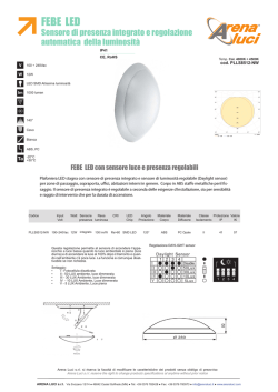
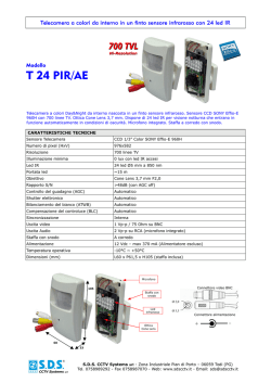
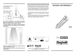
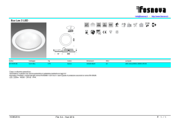
AECO_115-138_2012.qxp:AECO_115-138_2010
24-10-2012
16:24
Pagina 117
CONTROLLI DI LIVELLO CAPACITIVI
CAPACITIVE LEVEL CONTROLS
MORE THAN SENSORS
AECO_115-138_2012.qxp:AECO_115-138_2010
24-10-2012
16:24
Pagina 118
CONTROLLI DI LIVELLO CAPACITIVI
SERIE SCA - SCF
CAPACITIVE LEVEL CONTROLS
SCA - SCF SERIES
PRINCIPIO DI FUNZIONAMENTO
WORKING PRINCIPLE
Tale principio è basato sul comportamento fisico di un condensatore elettrico, la cui capacità dipende dall’area delle armature affacciate, dalla distanza fra di loro e dalla costante
dielettrica del materiale interposto.
Nel caso di controllo di livello capacitivo le armature del condensatore sono rappresentate
dalle pareti del serbatoio da un lato e dall’elettrodo di una sonda dall’altro (isolato dalle
pareti e che sporge all’interno dello stesso).
Rimanendo costanti la superficie dell’elettrodo e delle
pareti del serbatoio l’unica variabile è il materiale da
controllare che funge da dielettrico. La costante dielettrica relativa dell’aria o del vuoto è uguale a 1, mentre
quella di ogni altro materiale è per definizione superiore
a 1, quindi variando la quantità di materiale del serbatoio
si avrà una variazione di capacità del condensatore
che viene rilevata applicando agli elettrodi una tensione
alternata ad alta frequenza e all’aumentare della
capacità, conseguente al crescere del livello di riempimento, cresce anche la corrente che fluisce nel
condensatore.
Tale intensità di corrente ad alta frequenza viene
trasformata dalla centralina in una corrente continua
utilizzata per l’indicazione del livello.
The principle is based on the behavior of a capacitor the capacitance of which depends on
the area of the armatures in the vicinity, the distances between them and the dielectric constant of the material.
In the case of a capacitive level control the armatures of the capacitor are represented by
the walls of the tank on one side and by the electrode of a probe, isolated from the walls
on the other.
As the surfaces of the electrode and the walls of the
tank remain constant the only variable is the material
which acts as the dielectric. The dielectric constant
relative to air or vacuum is 1, whilst by definition that
of any other material is greater than 1, therefore by
varying the quantity of material in the tank the capacitance of the capacitor is varied and this is measured
by applying to the electrodes a high frequency alternating voltage and as the capacitance increases as a
result in the increasing level in the tank the current
flowing in the capacitor also increases.
This value of frequency current is transformed by the
control circuit into a current which is used to indicate
the level.
APPLICAZIONI
APPLICATIONS
I controlli di livello capacitivi trovano largo impiego
dove necessiti controllare con notevole sicurezza di
intervento il livello di sostanze anche non conduttrici
sia liquide che solide.
Sono particolarmente utilizzati per il controllo del
livello nei silos per cereali e foraggi, nei mangimifici,
pastifici, sementifici, biscottifici e nell’industria
alimentare in genere.
Negli impianti di trasporto, dosaggio, stoccaggio e
lavorazione di materie plastiche e prodotti petrolchimici, nelle fonderie e cementifici.
Il campo di impiego è comunque vastissimo e applicabile in ogni situazione dove si presenti
la necessità di controllare il livello in serbatoi contenenti materiali di ogni genere.
Capacitive level controls are widely used where it is
necessary to control with a good safety margin of
intervention the level of substances both liquid and
solid which may not be conductive.
They are particularly used in silos for cereals, foodstuffs, seeds, biscuit plants and the food industry in
general.
They are also used in the transport, dosing, stocking
and handling of plastic materials, petrochemical
products, in foundries and cement factories.
The field of use is vast and is practically anywhere
where it is necessary to control the level inside tanks which contain many types of different material.
REGOLAZIONE DELLA SENSIBILITÀ
SENSITIVITY ADJUSTMENT
Dopo aver installato la sonda, se il serbatoio non è conduttore, effettuare la messa a terra
tramite apposito morsetto situato nella sonda stessa. Per una corretta taratura della sensibilità è consigliabile agire sul potenziometro di regolazione, con elettrodo libero da materiale,
fino a trovare il punto di intervento del relè ed annotare la posizione del potenziometro.
Quindi immergere l’elettrodo nel materiale da controllare, agire sul potenziometro fino a
trovare il punto di intervento del relè ed annotarne la posizione. Come ultima operazione posizionare il potenziometro nel
punto intermedio a quelli
trovati nelle due prove
precedenti.
L’apparecchiatura è dotata di un selettore di sicurezza min./max livello da
posizionare opportunamente in funzione del
controllo da effettuare.
After having installed the probe, if the tank is not conductive, carry out the earthing of the
probe by connecting to the connector placed on the probe. In order to calibrate the sensitivity the adjustment potentiometer should be adjusted with the probe free from material
until the point at which the relay switches is found and this should be noted on the potentiometer. The probe should then be immersed in the material to be controlled and the potentiometer should be adjusted
once again until the relay
switches, once again note
the position. As a last operation place the position of
the potentiometer in the
mid position between the
two markings. Supplied
with a min/max level security switch which can be
positioned depending on
the control function that is
to be carried out.
LIMITATIONS
LIMITAZIONI
Nell’utilizzo di sonde capacitive bisogna tenere presente che notevoli formazioni di depositi sulla sonda possono falsare o impedire la misura, anche se
ciò è da escludersi nella maggior parte dei casi perchè gli elettrodi sono ricoperti in teflon antiaderente.
Il valore della costante dielettrica del materiale non deve essere troppo piccolo, deve comunque differire significativamente da 1. Inoltre bisogna tenere conto della composizione
del materiale, contenuto di umidità, temperatura ecc.
1
When using capacitive
probes is should be borne
in mind that large deposits
adhering to the probe may
affect the measurement,
this can however, be discounted in most cases as
the probe is covered in teflon.
The value of the dielectric constant of the material must not be too low, it must in any case
differ significantly from 1, furthermore it is important to bear in mind the composition of the
material, humidity content, temperature etc.
AECO_115-138_2012.qxp:AECO_115-138_2010
24-10-2012
16:24
Pagina 119
CONTROLLI DI LIVELLO CAPACITIVI
SERIE SCA - SCF
CAPACITIVE LEVEL CONTROLS
SCA - SCF SERIES
CARATTERISTICHE GENERALI
GENERAL CHARACTERISTICS
Queste apparecchiature ad esecuzione compatta presentano la parte meccanica e la parte
elettronica alloggiate in una unica unità.
Sono fornite con elettrodi ad asta in acciaio (SCA) rivestiti in teflon con lunghezze standard
300/500/800mm oppure con elettrodi a fune (SCF) in acciaio plastificato ed elemento tenditore rivestito in teflon con lunghezze standard 1000/2000/3000/4000 mm facilmente accorciabili. Il corpo meccanico della sonda è in fusione di alluminio provvisto di due pressacavi di uscita, attacco standard filettato da 1” ½ GAS fornibile anche da 1” oppure 2” GAS.
Tale custodia ha un grado di protezione IP65 che ne consente l’installazione all’aperto.
These compact devices come with the electronics and mechanics fit in a whole unit.
They are supplied with bar electrodes of teflon coated steel (SCA) with standard lenghts of
300 - 500 - 800 mm, or with cable electrodes which are of plastified steel and tensioning,
weight covered in teflon (SCF) with standard lenghts of 1.000 - 2.000 - 3.000 - 4.000 mm,
these are easily shortened.
The body of the SC probe is an aluminium casting with two cable clamps on the outputs,
standard fixing 1 1/2" GAS, available also 1" ore 2" GAS. The body has a degree
of protection of IP 65 which allows for outside installation.
CARATTERISTICHE TECNICHE / TECHNICAL CHARACTERISTICS
Tensione di alimentazione / Supply voltage
Assorbimento max (a relè eccitato) / Max absorption (relay on)
Uscita a relè 1 scambio / Relay output with 1 pole change over
Grado di protezione / IP Rating
Sensibilità regolabile / Sensitivity adjustment
Led visualizzatore rosso / Red led
Limiti di temperatura / Temperature limits
Custodia / Housing
Attacco filettato / Standard fixing
Pressione max nel serbatoio / Max tank pressure
SCHEMA DI COLLEGAMENTO / WIRING DIAGRAM
DIMENSIONI / DIMENSIONS (mm)
SCA
24Vac-110/220Vac+-15% 50-60Hz
2,5VA
5A a 220 Vac
IP 65
Presente / Incorporated
Indicazione relè on-off / Relay indicator on-off
-20 ÷ +60°C
Alluminio / Aluminium
1 ½ inch Gas
12Kg/cmq
SCF
SCA / SCF
REG. SENSIBILITÀ
SENSITIVITY ADJ.
LED
Nei modelli con alimentazione a 24Vca collegarsi ai morsetti 2-4
In the case of 24Vac type supply connect to terminals 2-4
MODELLI CON CENTRALINO AMPLIFICATORE SEPARATO
MODELS WITH SEPARATE AMPLIFIER GEARBOX
Questa versione viene fornita esclusivamente su richiesta, presenta la parte meccanica
uguale alle sonde SCA/SCF, con all’interno un oscillatore a transistor collegato ad un centralino elettronico esterno per amplificazione del segnale e regolazione della sensibilità.
Per informazioni dettagliate contattare il ns. ufficio tecnico.
This version is supplied upon request only. From a mechanical point of view it is the same
as the SCA/SCF series, with an internal oscillator transistor connected to the external electronic amplifier to improve signal and to adjust sensitivity. For further tech. info. pls. contact
our technical dept.
2
AECO_1-69_2012:AECO_1-69_2010
24-10-2012
16:14
Pagina 66
SENSORI DI PROSSIMITÀ CAPACITIVI
SERIE SC
PROXIMITY CAPACITIVE SENSORS
SC SERIES
PRINCIPIO DI FUNZIONAMENTO
WORKING PRINCIPLE
I sensori di prossimità capacitivi contengono un
oscillatore a transistor situato nella parte anteriore. Il circuito oscillante R-C (resistenza-condensatore) viene influenzato dalla variazione di
capacità, infatti quando un materiale qualsiasi
solido o liquido (acqua, vetro, legno, metallo,
caffé, polveri, ecc.) interessa la superficie attiva
del sensore, la capacità aumenta mettendo in
azione l’oscillatore fino ad invertire la soglia del
trigger, inducendo un cambiamento di condizione
dello stadio finale ed il conseguente comando di
un carico esterno. Un potenziometro permette la
regolazione fine della distanza di intervento. Tutti
i sensori sono protetti alle inversioni di polarità,
a disturbi elettrici di origine induttiva e sono forniti
con protezione al corto circuito permanente del
carico. Possono essere forniti ad intervento rapido
o temporizzato. Le parti plastiche dei sensori
capacitivi (custodie, tappi, codoli e ghiere) sono
realizzate in Makrolon, materiale plastico atossico,
antistatico e resistente all’abrasione.
Capacitive sensors contain an oscillator transistor
in the front section. The oscillating circuit R-C
(resistor-capacititor) is influenced by variations
in capacity in fact when any material, solid or
liquid (water, wood, metals, coffee, powders,
etc.) come into contact with the active surface
of the sensor the capacitance increases putting
into action the oscillator up until the threshold of
trigger inverts. By introducing a change in the
condition of the final stage and therefore in the
command of the external load a potentiometer
makes fine adjustements to the switching
distance. All the sensors are protected against a
change of polarity and electrical disturbances of
inductive origin, and they are protected against
short circuits.
They can be supplied with rapid or delayed
switching. The plastic parts of the capacitive
sensors (body, plugs, oulets and locknuts) are
made of makrolon which is not toxic, non static
and resistant to abrasives.
SCHEMA A BLOCCHI DI SENSORE AMPLIFICATO
CHOICE OF A CAPACITIVE SENSOR
BLOCK DIAGRAM OF AMPLIFIED CAPACITIVE SENSOR
When choosing a capacitive sensor the final use
Nella scelta di un sensore capacitivo si deve
should be kept in mind, that is the material to be
tenere presente l’utilizzo finale, cioé il materiale
controlled, its form and composition.
da controllare, la sua forma e la composizione.
The reduction factors related to every material
Si deve porre molta attenzione ai fattori di ridushould be remembered and also their physical
zione dei vari materiali e della loro massa fisica.
mass.
È comunque consigliabile nell’uso dei sensori
If possible it is recommended to use not emcapacitivi, se le circostanze lo consentono, l’utibeddable model, that is not mounted flush with
lizzo dei modelli parzialmente schermati cioé
the surface as it is possible to take advantage of
non montabili a filo metallo perché si può contare
the much greater sensitive field, this means that the sensor need not be set to the maxisu un’ampiezza di capo sensibile molto superiore e la sensibilità non necessita di essere
mum where it would be more prone to effects from temperature variations, humidity,
spinta all’eccesso causando a volte eccitazioni non volute a causa di variazioni di temperapowder deposits, etc.
tura, umidità, depositi di polvere ecc. Se invece l’installazione consente solo l’utilizzo di
If it is necessary to install the sensor flush with the surface it is advised to make a setting
sensori totalmente schermati, per montaggio a filo metallo, accertarsi che la sensibilità
which is not too close to the maximum.
occorrente per il buon funzionamento non sia molto spinta. La differenza sostanziale tra i
The main difference between the totally screened and partially screened types of sensors
due modelli è che a parità di distanza di intervento tra un sensore totalmente ed uno paris that at equal intervention distances the former requires a sensitivity of about the double
zialmente schermato, il primo necessita di una sensibilità all’incirca doppia del secondo per
of the latter and therefore functions under more critical conditions.
funzionare e quindi lavora in condizioni più critiche.
SCELTA DI UN SENSORE CAPACITIVO
NORME DA RISPETTARE PER UNA CORRETTA INSTALLAZIONE
TOTALMENTE SCHERMATI / EMBEDDABLE
Montaggio affiancato
Side by side mounting
Montaggio a filo
Flush mounting
INSTRUCTIONS FOR CORRECT INSTALLATION
PARZIALMENTE SCHERMATI / NOT EMBEDDABLE
Montaggio affiancato
Side by side mounting
Montaggio a filo
Flush mounting
APPLICAZIONI
APPLICATIONS
I sensori capacitivi trovano largo impiego nelle applicazioni dove il materiale da controllare
non è necessariamente metallo. Sono ampiamente utilizzati come controlli di livello minimo
e massimo di liquidi, prodotti in polvere, granulari ecc. oppure per conteggio o rilevazione
di pezzi metallici e non metallici.
Capacitive sensors are used widely as limit switches which are sensitive to all types of materials, as limit controls for sensing the maximum and minimum levels of liquids, powders,
granules, etc. in silos and various containers. They can also be used for sensing or counting metallic and non metallic objects.
REGOLAZIONE DELLA SENSIBILITÀ
SENSITIVITY ADJUSTMENT
La regolazione della sensibilità è consigliabile venga effettuata quando il sensore è installato
nella posizione definitiva di funzionamento e deve essere regolata in posizione intermedia
tra il minimo ed il massimo della sensibilità. Infatti l’aria fa da dielettrico e quindi si deve
tener presente che una forte variazione di umidità della stessa può portare, se la regolazione
è molto spinta, ad eccitazioni non volute. La distanza di intervento è in funzione del materiale e delle dimensioni dell’oggetto da controllare, dati che si possono rilevare dalla tabella
dei fattori di riduzione. Può variare in funzione della variazione di temperatura di circa il
± 10% della sensibilità regolata in un campo da -20 ÷ + 70°C. La sensibilità aumenta
ruotando il trimmer in senso orario e diminuisce ruotandolo in senso antiorario.
Per eseguire tale operazione si deve togliere la vite plastica di protezione del trimmer,
posta sul retro del sensore. Se la struttura dove viene fissato meccanicamente il sensore è
metallica, accertarsi che la stessa sia collegata a massa per evitare eventuali alterazioni
della distanza di intervento del sensore.
It is advisable that the sensitivity adjustment be carried out when the sensor is connected
in the definite operational position and should be adjusted at the intermediate position between the minimum and maximum values. In the working of the capacitive sensor the air
acts as dielectric and it is necessary to take into account that strong variation of humidity
can cause, if the adjustment is very fine, a variation of the same. The sensing range is determined in respect to the material and object dimensions to be controlled and can change
in respect to the variation of the temperature of about 10% at a temperature of -20 ÷
+70°C. The sensitivity increases when the trimmer is rotated in the clockwise direction and
decreases in the anti-clockwise direction.
The adjustment can be carried out once the plastic protection screw is removed. If the
sensor is mounted on a metallic support it is necessary to make an earth connection in
order to avoid alterations in the sensing distance of the sensor.
3
AECO_1-69_2012:AECO_1-69_2010
24-10-2012
16:14
Pagina 67
SENSORI DI PROSSIMITÀ CAPACITIVI
SERIE SC
PROXIMITY CAPACITIVE SENSORS
SC SERIES
MODELLI AD INTERVENTO TEMPORIZZATO
DELAYED MODELS
Sono sensori capacitivi che forniscono il segnale di uscita al carico esterno con una temporizzazione regolabile alla eccitazione o alla diseccitazione con funzioni N.O. oppure N.C. Vengono
forniti nei modelli diam. 18, 30 e 40 mm ed in corrente alternata. Le gamme di temporizzazione disponibili sono le seguenti: 0 ÷ 1 min. / 0 ÷ 10 min. nei modelli diam. 18 e 30 e
1 sec. ÷ 1 min. / 15 sec. ÷ 15 min. nei modelli diam. 40.
Un trimmer di regolazione dei tempi, permette l’impostazione del tempo desiderato. Questi sensori possono trovare diverse applicazioni nel campo industriale ed in particolare nell’industria
alimentare come controlli di livello e precisamente dove necessita un segnale ritardato senza
l’interposizione di un temporizzatore esterno tra sensore e carico. Per effettuare la regolazione della sensibilità in questi modelli azzerare prima il trimmer di temporizzazione.
These are capacitive sensors which give an output signal to the load which can have an adjustable time delay. To its energization and deenergization switching in both N.O. and N.C.
types. They are supplied only in the Ø 18, 30 and 40 mm model A.C. The available ranges
of delay are the following: 0 ÷ 1 min. / 0 ÷ 10 min. in the Ø 18 and Ø 30 model and
1 sec. ÷ 1 min. / 15 sec. ÷ 15 min. in the Ø 40 model.
A trimmer for adjusting the time has a scale of 0 to 100. These sensors are used in different industrial applications, particularly in the food industry as level controls where a time
delay is specifically required without having to install an external timer between the sensor
and the load.
MODELLI E FUNZIONI DISPONIBILI
AVAILABLE RANGE AND FUNCTIONS
SC18SP-AE10 / SC30SP-AE25 / SC40P-AE35 TE NO - ritardo all’eccitazione contatto N.O.
Il sensore in assenza di materiale ha il contatto aperto. Quando il materiale entra nella zona
sensibile parte il tempo impostato dopo il quale il contatto si chiude. Quando esce il contatto
si riapre istantaneamente.
SC18SP-AE10 / SC30SP-AE25 / SC40P-AE35 TE NO delay on energization N.O. contact
In the absence of material the sensor has an open contact. When the material enters the sensing
area, the delay set starts. A the end of this time the contact closes. When the material leaves the
sensing area, the contact opens instantaneously.
SC18SP-AE10 / SC30SP-AE25 / SC40P-AE35 TE NC - ritardo all’eccitazione contatto N.C.
Il sensore in assenza di materiale ha il contatto chiuso. Quando il materiale entra nella zona
sensibile il contatto si apre e quando esce parte il tempo impostato dopo il quale il contatto
si chiude.
SC18SP-AE10 / SC30SP-AE25 / SC40P-AE35 TE NC - delay on energization N.C. contact
In the absence of material the contact of the sensor is closed. When material enters the
sensing area, the contact opens. When material leaves the area, the delay set starts, after
which the contact closes.
SC18SP-AE10 / SC30SP-AE25 / SC40P-AE35 TD NO - ritardo diseccitazione contatto N.O.
Il sensore in assenza di materiale ha il contatto aperto. Quando il materiale entra nella zona
sensibile il contatto si chiude e quando esce parte il tempo impostato dopo il quale il contatto
si apre.
SC18SP-AE10 / SC30SP-AE25 / SC40P-AE35 TD NO - delay on de-energization N.O. contact
In the absence of material the contact of the sensor is open. When material enters the
sensing area, the contact closes. When material leaves the area, the delay set starts, after
which the contact opens.
SC18SP-AE10 / SC30SP-AE25 / SC40P-AE35 TD NC - ritardo diseccitazione contatto N.C.
Il sensore in assenza di materiale ha il contatto chiuso. Quando il materiale entra nella zona
sensibile parte il tempo impostato dopo il quale il contatto si apre, quando esce il contatto si
chiude istantaneamente.
SC18SP-AE10 / SC30SP-AE25 / SC40P-AE35 TD NC - delay on de-energization N.C. contact
In the absence of material the contact of the sensor is closed. When material enters the
sensing area, the delay set starts, after which the contact opens. When material leaves the
area, the contact closes instantaneously.
I modelli diam. 18 e 30 sono forniti con contatto preimpostato su NO e possono essere
trasformati NC tramite commutatore.
M 18 and M 30 versions are supplied with NO contact and can be changed to NC by means
of a selector switch.
REGOLAZIONE DEL TEMPO DI RITARDO
TIME DELAY ADJUSTMENT
Modelli SC18SP-AE10T e SC30SP-AE25T
La regolazione del tempo di ritardo va effettuata successivamente alla programmazione del
tipo di uscita NO o NC ed esclusivamente a sensore alimentato. Il tempo di ritardo aumenta
da “0” al valore massimo preimpostato “1min” o “10min”, a seconda del modello, ruotando il
trimm in senso orario. Quando la temporizzazione è attiva il LED BLU lampeggia con una frequenza proporzionale al tempo di ritardo:
-Frequenza di lampeggio bassa = Tempo di riterdo lungo
-Frequenza di lampeggio alta = Tempo di ritardo breve
SC18SP-AE10T e SC30SP-AE25T Models
Time delay adjustment must be performed after the sensivity setting and only with the device
powered UP. Time delay increases from “0” to the maximum scale range of “1min” or “10min”
by turning the trimmer clockwise. When timing is activated the BLUE LED flashes at a frequency proportional to the time delay:
-Low Flashing frequency = long time delay
-High Flashing frequency = short time delay
Modelli SC30P-RE25T e SC40P-AE35T
Per questi modelli vedi rispettivamente a pag. 78 e pag. 76.
SC30P-RE25T e SC40P-AE35T Models
for these models see page 78 and page 76.
ESEMPI DI MODELLI CON REGOLAZIONE DELLA TEMPORIZZAZIONE / EXAMPLES OF MODELS WITH TIME DELAY ADJUSTMENT
Sensitivity adjustment
Regolazione ritardo
Regolazione ritardo
selezione NO/NC
Delay setting
NO/NC setting
REG. TEMPO
TIME ADJUST.
Led timer
Timer led
Cavo / Cable
Led uscita Connettore / H plug
Output led
CAVO / CABLE
SC30P-RE25T
SC40P-AE35T
SC30SP-AE25T
SC18SP-AE10T
COLLEGAMENTI CON ATTACCO H-K
CONNECTIONS WITH H-K PLUG
Vista del connettore maschio / (Vedere connettori femmina pag. 116)
View of male connector / (See female connectors page 116)
1
2
H (M12)
H (M12)
1
2
1
2
1
3
4
2
=
=
=
=
Marrone / +
Blu / -Nero / Uscita NPN - PNP / NO
Bianco / Uscita NPN - PNP / NC
1
3
4
2
=
=
=
=
Brown / +
Blue / -Black / Output NPN - PNP / NO
White / Output NPN - PNP / NC
/
/
/
/
4 NO - NC Programmabile
3=
4 NO - NC Programmable
3=
N.B.
N.B.
Utilizzare esclusivamente un connettore
a cablare
Use a connector to be connected only
3
4
K (Mod 12)
1
2
4
3
= Blu / -= Marrone / +
/
= Nero / Uscita NPN - PNP / NO
= Bianco / Uscita NPN - PNP / NC
1
2
4
3
= Blue / -= Brown / +
/
= Black / Output NPN - PNP / NO
= White / Output NPN - PNP / NC
K (Mod 12)
VISTA DEL CONNETTORE MASCHIO K
1/2=
NO - NC Programmabile
VIEW OF MALE CONNECTOR K
1/2=
NO - NC Programmable
4
AECO_1-69_2012:AECO_1-69_2010
24-10-2012
16:14
Pagina 68
SENSORI DI PROSSIMITÀ CAPACITIVI
SERIE SC
PROXIMITY CAPACITIVE SENSORS
SC SERIES
SENSORI IN ESECUZIONE C PER CORRENTE CONTINUA (4 FILI)
SENSORS VERSION
Sono sensori amplificati in corrente continua che oltre all’oscillatore hanno incorporato
anche l’amplificatore di uscita. Vengono forniti a 4 fili con funzione antivalente nelle versioni NPN o PNP. In questa esecuzione i sensori presentano come caratteristiche standard la
protezione contro il corto circuito permanente del carico, sicurezza assoluta contro l’inversione di polarità e protezione ai picchi prodotti dal disinserimento dei carichi induttivi.
Possono essere forniti in abbinamento agli alimentatori mod. ALNC - ALTP.
Sono compatibili con ingressi di controllori programmabili.
These are amplified D.C. sensors which contain an output amplifier in addition to the
oscillator.
They are supplied as 4 wires with antiphase outputs in the types NPN and PNP.
As standard, this version of sensor is protected against short circuit, absolutely protected against polarity inversion and current peaks created by the disconnection of
inductive loads. These sensors can be supplied with power supplies: ALNC - ALTP.
They are adapted for inputs of programmable controllers.
SENSORI IN ESECUZIONE A PER CORRENTE ALTERNATA E CONTINUA (2 FILI)
SENSORS VERSION A FOR ALTERNATING OR DIRECT VOLTAGE (2 WIRES)
Sono sensori amplificati a due fili in grado di funzionare sia con tensioni alternate che continue. Questi dispositivi oltre all’oscillatore, hanno incorporato anche un amplificatore di
uscita a Mosfet, in grado di aprire e chiudere un carico molto velocemente.
Il carico, essendo collegato in serie al sensore, viene attraversato dalla stessa corrente
residua che lo alimenta. In particolare è necessario prestare molta attenzione ai relè a
basso consumo. Infatti bisogna accertarsi che:
- la corrente richiesta per la sicura eccitazione del relè sia UGUALE o SUPERIORE alla
“corrente minima di uscita” richiesta dal sensore;
- la corrente richiesta per la sicura diseccitazione del relè sia SUPERIORE alla “corrente
residua” del sensore.
Non rispettando questi accorgimenti si otterrà una commutazione incerta del relè.
Inoltre è opportuno prestare attenzione ai collegamenti ad ingressi ad alta impedenza dei
comandi elettronici, in quanto la corrente residua del sensore potrebbe essere sufficiente
ad attivarli.
Nello stato di chiusura si verifica invece ai capi del sensore una caduta di tensione che
deve essere considerata soprattutto nel caso di basse tensioni di alimentazione.
Tutti i sensori capacitivi CA/CC sono protetti al cortocircuito (fino a 50 Vcc e 250 Vca).
Sono inoltre dotati di una efficace protezione ai transitori di tensione provenienti dalla rete
o generati dal carico. Sono compatibili con ingressi di controllori programmabili.
These are amplified sensors with two wires which function both in A.C. and D.C., these products as well as having an oscillator have a mosfet output amplifier incorporated which is able to open and close a load very quickly.
The load which is connected in series with the sensor is passed through by the same residual current that it is supplied by. It is particularly important to pay attention
to the low consumption relay, in fact it is important to ensure that:
- the required current for the switching of the relay is EQUAL to or SUPERIOR to the
minimum output current required by the sensor;
- the current required of the secure releasing of the relay is SUPERIOR to the residual
current of the sensor.
If these parameters are not respected there will be an uncertain switching of the relay.
Furthermore attention must be given to high impedance input connections of electronic commands as the residual current in the sensor could be sufficient to cause
activation.
In the closed state a voltage drop can be found this should be taken into account
especially when there is a low voltage supply.
All AC/DC capacitive sensors are short circuit protected (up to 50 Vdc and 250 Vac).
They are also protected against voltage transients coming from the power supply or
generated by the load. They are compatible with P.L.C. units.
SENSORI IN ESECUZIONE R CON relè (5 FILI)
SENSORS VERSION
Sono sensori amplificati in grado di funzionare sia con tensioni alternate che continue.
Questi dispositivi, oltre all’oscillatore e all’amplificatore, hanno incorporato anche un relè
che fornisce un contatto di uscita in scambio da 1A a 220Vca.
Il carico esterno può essere collegato al contatto NO oppure NC del relè suddetto; tale
soluzione garantisce una maggior sicurezza in presenza di carichi elevati (fino a 1A) a
differenza dei sensori ad uscita statica.
Sono disponibili modelli ad intervento istantaneo (pag. 75) o temporizzato con funzioni
programmabili (pag. 78).
These are amplified sensors which can operate with both AC and DC power supplies.
The sensors as well as the oscillator and amplifier have incorporated a relay which
provides one changeover output contact from 1Amp. at 220 Vac.
The external load can be connected to the NO or NC contact of the relay, this solution guarantees greater security in the presence of high loads (up to 1A) which is different to sensors with output.
Types with instantaneous intervention are available (page 75) or delayed with programmable functions (page 78).
C FOR DIRECT VOLTAGE (4 WIRES)
R WITH RELAY (5 WIRES)
SCHEMI DI COLLEGAMENTO / WIRING DIAGRAMS
5
ESECUZIONE C / VERSION C
MARRONE/BROWN
ESECUZIONE A / VERSION A
6
BIANCO/WHITE
BLU/BLUE
GIALLO/VERDE
YELLOW/GREEN
BLU/BLUE
MARRONE/BROWN
NERO/BLACK
7
ESECUZIONE R / VERSION R
MARRONE/BROWN
RELÈ
BIANCO/WHITE
ROSSO/RED
NERO/BLACK
MARRONE/BROWN
NERO/BLACK
BIANCO/WHITE
BLU/BLUE
Vdc/ac
BLU/BLUE
BLU/BLUE
GIALLO/VERDE
YELLOW/GREEN
MARRONE/BROWN
ALIMENTAZIONE DI SENSORI CAPACITIVI IN CORRENTE CONTINUA
SUGGESTION FOR SUPPLYING VOLTAGE TO CAPACITIVE SENSORS
ESEMPIO A / EXAMPLE A
ESEMPIO B / EXAMPLE B
Stabilizzatore/Voltage stabilizer
Vac
50-60 Hz
Vac
50-60 Hz
Vac
Vdc
5
Vac
Vdc
La tensione di alimentazione deve essere adeguata alle caratteristiche dei dispositivi usati.
Usare sempre trasformatori con tensione di secondario Vca inferiore alla tensione continua
desiderata Vcc. La tensione Vca di secondario da utilizzare si ricava così:
Vca = (Vcc + 1) : 1,41
The supply voltage should be adjusted according to the characteristics of the sensor used. It is
recommended to use a trasformer with secondary voltage Vac lower than the direct voltage Vdc
required. The secondary voltage Vac is found as follows:
Vac = (Vdc + 1) : 1,41
Inoltre la tensione continua Vcc di alimentazione dei dispositivi deve essere filtrata con una
capacità C di almeno 470 µF per ogni 200 mA prelevati dall’alimentatore.
Se la tensione continua a disposizione è elevata utilizzare esclusivamente lo schema B con un
adeguato stabilizzatore di tensione.
The supply voltage Vdc of the sensor should be filtered with a capacity C at least 470 µF for each
200 mA used.
If the supply voltage Vdc is high it is recommended to follow the diagram B with a proper
voltage stabilizer.
AECO_1-69_2012:AECO_1-69_2010
24-10-2012
16:14
Pagina 69
CAPACITIVE SENSORS
APPLICATION EXAMPLES
SENSORI CAPACITIVI
ESEMPI DI APPLICAZIONE
CONTROLLO DI LIVELLO A CONTATTO
DI MATERIALI SOLIDI O LIQUIDI
CONTACT LEVEL CONTROL
FOR SOLIDS OR LIQUIDS
CONTROLLO DI LIVELLO ATTRAVERSO
SERBATOI NON METALLICI
LEVEL CONTROL FOR NON
METALLIC CONTAINERS
CONTROLLO PRESENZA MATERIALI
SOLIDI O LIQUIDI ATTRAVERSO IMBALLI
O CONTENITORI NON METALLICI
SOLID OR LIQUID MATERIAL PRESENCE
CONTROL WHICH ARE INSIDE PACKAGING
OR NON METALLIC CONTAINERS
CONTROLLO DI LIVELLO IN SERBATOI METALLICI
ATTRAVERSO FINESTRELLA IN VETRO O PLASTICA
LEVEL CONTROL FOR METAL CONTAINERS
USING PLASTIC OR GLASS WINDOWS
CONTROLLO DEL LIVELLO IN ALTEZZA
DI PILE DI CARTA
CONTROLLING THE HEIGHT
OF A PAPER STACK
CONTROLLO ROTTURA NASTRO
IN BOBINE DI MATERIALE NON METALLICO
(CARTA, PLASTICA, ECC.)
CONTROLLING THE BREAKAGE IN REELS
OF NON METALLIC MATERIAL (PAPER,
PLASTIC ETC.)
CONTROLLO AUTOMATICO DI RIEMPIMENTO
FILLING CONTROL
TUBAZIONE
NON METALLICA
CONTROLLO DI
FLUSSO DI FLUIDI
LIQUID FLOW
CONTROL
CONTROLLO PRESENZA,
CONTEGGIO E SMISTAMENTO
AUTOMATICO DI PEZZI
METALLICI E NON METALLICI
AUTOMATIC PRESENCE
COUNTING AND SORTING
CONTROL OF METALLIC
AND NON METALLIC ARTICLES
UNLOADING TIME MAX 15 MIN.
CARICO MATERIALE / LOADING
TEMPO MAX. DI SCARICO 15 MIN.
NON METALLIC
TUBING
CONTROLLO DI LIVELLO
CON SENSORE TEMPORIZZATO
(NELL'ESEMPIO: SC40P - AE35 TE15' NC)
LEVEL CONTROL WITH DELAYED SENSOR
(IN THE EXAMPLE SC40P - AE35 TE15' NC)
CONTROLLO DI LIVELLO IN SERBATOI
CONTENENTI MATERIALI DA -200° ÷ +250°C
(NELL'ESEMPIO: SC30M-HT CON AMPLIFICATORE ALSC A DISTANZA)
CONTROL IN TANKS WITH MATERIAL -200C° +250C°
(IN THE EXAMPLE: SC30M-HT WITH SEPARATE ALSC AMPLIFIER)
6
AECO_70-80_2012.qxp:AECO_70-80_2010
24-10-2012
16:02
Pagina 70
SENSORI CAPACITIVI M18 x 1 • CAPACITIVE SENSORS M18 x 1
• CUSTODIA CILINDRICA PLASTICA O METALLICA
• CYLINDRICAL HOUSING PLASTIC OR METALLIC
• MODELLI 4 FILI IN C.C. - ESECUZIONE-C
• 4 WIRES D.C. MODELS - VERSION-C
TOTALMENTE SCHERMATI
EMBEDDABLE (FLUSH MOUNTING)
PARZIALMENTE SCHERMATI
NOT EMBEDDABLE (NON FLUSH MOUNTING)
CARATTERISTICHE TECNICHE
TECHNICAL CHARACTERISTICS
Dimensioni / Dimensions
mm
SC18SM - C5 NPN NO + NC
MODELLI CON CAVO
MODELS WITH CABLE
SC18SP - CE10 NPN NO + NC SC18SM - CE10 NPN NO + NC
C18000055
C18000061
SC18SM - C5 PNP NO + NC
SC18SP - CE10 PNP NO + NC SC18SM - CE10 PNP NO + NC
C18000052
C18000058
SC18SM - C5 NPN NO + NC H
MODELLI CON CONNETTORE
MODELS WITH CONNECTOR
C18000076
SC18SM - C5 PNP NO + NC H
mm
Tensione continua (ond. residua ≤ 10%)
Continuous voltage (residual ripple ≤10%)
V
Tensione alternata 50÷60 Hz
Alternating voltage 50÷60 Hz
V
Isteresi
Hysteresis
Frequenza max di lavoro
Switching frequency
Ripetibilità (a temperatura costante)
Repeatability (at constant temperature)
C18000074
0÷5
10 ÷ 40 (Valori massimi assoluti ripple incluso / absolute maximum ratings ripple included)
% Sn
≤ 20
Hz
10
Corrente max di uscita
Max output current
mA
200
Corrente min di uscita
Min output current
mA
A
Assorbimento a 24Vcc
Absorption at 24Vdc
mA
≤10
Corrente residua
Residual current
mA
≤1
V
< 1.8
Protezione al corto circuito
Short circuit protection
Presente
Incorporated
Led visualizzatore
Led
Presente
Incorporated
Limiti di temperatura
Temperature limits
°C
-20 ÷ +70
Grado di protezione
IP rating
IP
67
Plastica
Plastic
Custodia
Housing
Cavo PVC
PVC Cable
Schemi di collegamento
Wiring diagrams
Collegamento con connettore
Connection with connector
Norme per installazione
Instructions for installation
7
C18000075
0 ÷ 10
< 10
Caduta di tensione (uscita attivata)
Voltage drop (sensor ON)
C18000077
SC18SP - CE10 PNP NO + NC H SC18SM - CE10 PNP NO + NC H
% Sn
Corrente max di spunto per 20ms
Max. peak current for 20ms
C18000064
SC18SP - CE10 NPN NO + NC H SC18SM - CE10 NPN NO + NC H
C18000073
C18000071
Distanza di intervento Sn regolabile
Switching distance Sn adjustable
C18000067
3m
Ottone nichelato
Nickelled brass
Plastica
Plastic
Ottone nichelato
Nickelled brass
4 x 0.25 mm2
Vedi pag. 68 - fig. 5 / See page 68 - pict. 5
Attacco H (M12) - Vedi pag. 67 - fig. 1 / H Plug (M12) - See page 67 - pict. 1
Vedi pag. 67 / See page 67
AECO_70-80_2012.qxp:AECO_70-80_2010
24-10-2012
16:02
Pagina 71
SENSORI CAPACITIVI M18 x 1 • CAPACITIVE SENSORS M18 x 1
• CUSTODIA CILINDRICA PLASTICA SC18SP O METALLICA SC18SM
• CYLINDRICAL HOUSING PLASTIC SC18SP OR METALLIC SC18SM
SC18SP
• MODELLI 2 FILI IN C.A. - ESECUZIONE-A
• 2 WIRES A.C. MODELS - VERSION-A
SC18SP
SC18SP
• INTERVENTO ISTANTANEO O TEMPORIZZATO
• STANDARD AND DELAYED MODELS
Regolazione ritardo
41.5
7.5
92
SC18SM
SC18SM
SC18SP-A5 NO/NC
SC18SP
SC18SP-AE10 NO/NC
SC18SP-AE10 TE1' NO/NC
SC18SP-AE10 TD1' NO/NC
C18000083
C18000097
C18000101
SC18SM-AE10 NO/NC
SC18SP-AE10 TE10' NO/NC
SC18SP-AE10 TD10' NO/NC
C18000091
C18000098
C18000102
C18000079
SC18SM-A5 NO/NC
C18000087
SC18SP-AE10 NO/NC H
SC18SP-A5 NO/NC H
C18000082
SC18SP-AE10 TE1' NO/NC H SC18SP-AE10 TD1' NO/NC H
C18000086
C18000099
SC18SM-AE10 NO/NC H
SC18SM-A5 NO/NC H
Regolazione ritardo
C18000090
SC18SP-AE10 TE10' NO/NC H SC18SP-AE10 TD10' NO/NC H
C18000094
0÷5
C18000103
C18000100
0 ÷ 10
C18000104
0 ÷ 10
20 ÷ 250 (Valori massimi assoluti / absolute maximum ratings)
≤ 20
Max= 10 o in funzione del ritardo / In relation to delay
10
< 10
300
10 (Corrente minima di rilascio / min. release current)
1.5
≤1
≤2
≤6
Presente
Incorporated
Presente
Incorporated
Led giallo indicazione di stato - Led blu indicazione ritardo (Lampeggiante)
Yellow led status indicator - Blue led dalay time indicator (Blinking)
-20 ÷ +70
67
Plastica (SC18SP) - Ottone nichelato (SC18SM)
Plastic (SC18SP) - Nickelled brass (SC18SM)
Plastica
Plastic
3 x 0.35 mm2
Vedi pag. 68 - fig. 6 / See page 68 - pict. 6
Attacco H (M12) Vedi pag. 67 - fig. 2 / H Plug (M12) See page 67 - pict. 2
Vedi pag. 67 / See page 67
8
AECO_70-80_2012.qxp:AECO_70-80_2010
24-10-2012
16:02
Pagina 72
SENSORI CAPACITIVI M30 x 1,5 • CAPACITIVE SENSORS M30 x 1,5
• CUSTODIA CILINDRICA PLASTICA SC30SP O METALLICA SC30SM
• CYLINDRICAL HOUSING PLASTIC SC30SP OR METALLIC SC30SM
• MODELLI 4 FILI IN C.C. - ESECUZIONE-C
• 4 WIRES D.C. MODELS - VERSION-C
SC30SP
1
SC30SP
17
55
TOTALMENTE SCHERMATI
EMBEDDABLE (FLUSH MOUNTING)
15
41
17
Regolazione sensibilità
Sensitivity adjustment
Regolazione sensibilità
Sensitivity adjustment
Led
Led
Attacco HM12
H Plug M12
PARZIALMENTE SCHERMATI
NOT EMBEDDABLE (NON FLUSH MOUNTING)
SC30SM
1
CARATTERISTICHE TECNICHE
TECHNICAL CHARACTERISTICS
Cavo
Cable
101
86
SC30SM
17
55
15
Regolazione sensibilità
Sensitivity adjustment
17
41
Led
Regolazione sensibilità
Sensitivity adjustment
Led
Attacco HM12
H Plug M12
Dimensioni / Dimensions
101
mm
Cavo
Cable
86
SC30SP - C20 NPN NO + NC SC30SM - C20 NPN NO + NC SC30SP - CE25 NPN NO + NC SC30SM - CE25 NPN NO + NC
MODELLI CON CAVO
MODELS WITH CABLE
C30000030
C30000040
C30000050
C30000060
SC30SP - C20 PNP NO + NC SC30SM - C20 PNP NO + NC SC30SP - CE25 PNP NO + NC SC30SM - CE25 PNP NO + NC
C30000016
C30000035
C30000045
C30000055
SC30SP - C20 NPN NO + NC H SC30SM - C20 NPN NO + NC H SC30SP - CE25 NPN NO + NC H SC30SM - CE25 NPN NO + NC H
MODELLI CON CONNETTORE
MODELS WITH CONNECTOR
C30000020
C30000021
V
Tensione alternata 50÷60 Hz
Alternating voltage 50÷60 Hz
V
Frequenza max di lavoro
Switching frequency
Ripetibilità (a temperatura costante)
Repeatability (at constant temperature)
C30000019
C30000022
0 ÷ 20
mm
Tensione continua (ond. residua ≤ 10%)
Continuous voltage (residual ripple ≤10%)
Isteresi
Hysteresis
10 ÷ 60 (Valori massimi assoluti ripple incluso / absolute maximum ratings ripple included)
≤ 20
% Sn
10
Hz
< 10
Corrente max di uscita
Max output current
mA
200
Corrente min di uscita
Min output current
mA
A
Assorbimento a 24Vcc
Absorption at 24Vdc
mA
Corrente residua
Residual current
mA
Caduta di tensione (uscita attivata)
Voltage drop (sensor ON)
≤ 10
< 1.8
V
Protezione al corto circuito
Short circuit protection
Presente
Incorporated
Led visualizzatore
Led
Presente
Incorporated
Limiti di temperatura
Temperature limits
°C
-20 ÷ +70
Grado di protezione
IP rating
IP
67
Custodia
Housing
Cavo PVC
PVC Cable
Plastica
Plastic
3m
Ottone nichelato
Nickelled brass
Plastica
Plastic
Montaggio possibile / Possible mounting
Schemi di collegamento
Wiring diagrams
Vedi pag. 68 - fig. 5 / See page 68 - pict. 5
Norme per installazione
Instructions for installation
9
Ottone nichelato
Nickelled brass
4 x 0.25 mm2
Muffola di protezione
Protection housing
Collegamento con connettore
Connection with connector
C30000023
0 ÷ 25
% Sn
Corrente max di spunto per 20ms
Max. peak current for 20ms
C30000025
SC30SP - C20 PNP NO + NC H SC30SM - C20 PNP NO + NC H SC30SP - CE25 PNP NO + NC H SC30SM - CE25 PNP NO + NC H
C30000017
Distanza di intervento Sn regolabile
Switching distance Sn adjustable
C30000024
Attacco H (M12) - Vedi pag. 67 - fig. 1 / H Plug (M12) - See page 67 - pict. 1
Vedi pag. 67 / See page 67
AECO_70-80_2012.qxp:AECO_70-80_2010
24-10-2012
16:02
Pagina 73
SENSORI CAPACITIVI M30 x 1,5 • CAPACITIVE SENSORS M30 x 1,5
• CUSTODIA CILINDRICA PLASTICA SC3OSP METALLICA SC30SM
• CYLINDRICAL HOUSING PLASTIC SC30SP OR METALLIC SC30SM
SC30SP
1
• MODELLI 2 FILI IN C.A./C.C. - ESECUZIONE-A
• 2 WIRES A.C./D.C. MODELS - VERSION-A
SC30SP
17
55
15
Regolazione sensibilità
Sensitivity adjustment
• INTERVENTO ISTANTANEO O TEMPORIZZATO
• STANDARD AND DELAYED MODELS
SC30SP
41
17
15
Regolazione sensibilità
Sensitivity adjustment
41
17
Regolazione sensibilità
Sensitivity adjustment
Led
Led
D
Cavo
Cable
101
86
SC30SM
1
Regolazione ritardo
selezione NO/NC
Delay setting
NO/NC setting
Attacco HM12
H Plug M12
101
SC30SM
17
55
15
Regolazione sensibilità
Sensitivity adjustment
SC30SP
17
41
15
Regolazione sensibi
Sensitivity adjustmen
Led
41
Led timer
Timer led
Led uscita
Output led
17
Cavo / Cable
Connettore / H plug
Led
Attacco HM12
H Plug M12
101
Cavo
Cable
86
86
SC30SP - A20 NO/NC
SC30SP - AE25 NO/NC
SC30SP - AE25 TE1’ NO/NC
SC30SP - AE25 TD1’ NO/NC
C30000133
C30000137
C30000153
C30000185
SC30SM - A20 NO/NC
SC30SM - AE25 NO/NC
SC30SP - AE25 TE10’ NO/NC
SC30SP - AE25 TD10’ NO/NC
C30000141
C30000145
C30000169
C30000201
SC30SP - A20 NO/NC H
SC30SP - AE25 NO/NC H
SC30SP - AE25 TE1’ NO/NC H
SC30SP - AE25 TD1’ NO/NC H
C30000136
C30000140
C30000156
C30000188
SC30SM - A20 NO/NC H
SC30SM - AE25 NO/NC H
SC30SP - AE25 TE10’ NO/NC H
SC30SP - AE25 TD10’ NO/NC H
C30000144
C30000148
C30000172
C30000204
0 ÷ 20
0 ÷ 25
0 ÷ 25
20 ÷ 250 V (Valori massimi assoluti / absolute maximum ratings)
≤ 20
Max= 10 o in funzione del ritardo / In relation to delay
10
≤ 10
500
10 (Corrente minima di rilascio / min. release current)
1.5
≤1
≤2
≤6
Presente
Incorporated
Presente
Incorporated
Led giallo indicazione di stato - Led blu indicazione ritardo (Lampeggiante)
Yellow led status indicator - Blue led delay time indicator (Blinking)
-20 ÷ +70
67
Plastica (SC30SP) - Ottone nichelato (SC30SM)
Plastic (SC30SP) - Nickelled brass (SC30SM)
Plastica
Plastic
3 x 0.35 mm2
Montaggio possibile / Possible mounting
Vedi pag. 68 - fig. 6 / See page 68 - pict. 6
Attacco H (M12) - Vedi pag. 67 - fig. 2 / H Plug (M12) - See page 67 - pict. 2
Vedi pag. 67 / See page 67
10
AECO_70-80_2012.qxp:AECO_70-80_2010
24-10-2012
16:02
Pagina 74
SENSORI CAPACITIVI M30 x 1,5 • CAPACITIVE SENSORS M30 x 1,5
• CUSTODIA CILINDRICA PLASTICA O METALLICA
• CYLINDRICAL HOUSING PLASTIC OR METALLIC
• MODELLI 4 FILI IN C.C. - ESECUZIONE-C
• 4 WIRES D.C. MODELS - VERSION-C
TOTALMENTE SCHERMATI
EMBEDDABLE (FLUSH MOUNTING)
PARZIALMENTE SCHERMATI
NOT EMBEDDABLE (NON FLUSH MOUNTING)
CARATTERISTICHE TECNICHE
TECHNICAL CHARACTERISTICS
Dimensioni / Dimensions
REG. SENSIBILITÀ
SENSITIVITY ADJ.
REG. SENSIBILITÀ
SENSITIVITY ADJ.
REG. SENSIBILITÀ
SENSITIVITY ADJ.
mm
SC30M - C20 NPN NO+NC K SC30M - CE25 NPN NO+NC K SC30P - CE25 NPN NO+NC K
CAP000031
MODELLI CON CONNETTORE K
MODELS WITH K CONNECTOR
CAP000032
SC30M - C20 PNP NO+NC K SC30M - CE25 PNP NO+NC K SC30P - CE25 PNP NO+NC K
CAP000040
Distanza di intervento Sn regolabile
Switching distance Sn adjustable
mm
Tensione continua (ond. residua ≤ 10%)
Continuous voltage (residual ripple ≤10%)
V
Tensione alternata 50÷60 Hz
Alternating voltage 50÷60 Hz
V
Isteresi
Hysteresis
Frequenza max di lavoro
Switching frequency
Ripetibilità (a temperatura costante)
Repeatability (at constant temperature)
CAP000041
0 ÷ 20
0 ÷ 25
% Sn
Hz
10
Corrente max di uscita
Max output current
mA
300
Corrente min di uscita
Min output current
mA
A
Assorbimento a 24Vcc
Absorption at 24Vdc
mA
Corrente residua
Residual current
mA
≤ 10
V
< 1.8
Protezione al corto circuito
Short circuit protection
Presente
Incorporated
Led visualizzatore
Led
Presente
Incorporated
Limiti di temperatura
Temperature limits
°C
-20 ÷ +70
Grado di protezione
IP rating
IP
65
Custodia
Housing
Cavo PVC
PVC Cable
Muffola di protezione
Protection housing
Schemi di collegamento
Wiring diagrams
Collegamento con connettore
Connection with connector
Norme per installazione
Instructions for installation
11
0 ÷ 25
≤ 20
< 10
Caduta di tensione (uscita attivata)
Voltage drop (sensor ON)
CAP000042
10 ÷ 55
% Sn
Corrente max di spunto per 20ms
Max. peak current for 20ms
CAP000033
Ottone nichelato
Nickelled brass
3m
Ottone nichelato
Nickelled brass
Plastica
Plastic
4 x 0.25 mm2
Montaggio possibile / Possible mounting (SCM-K)
Vedi pag. 68 - fig. 5 / See page 68 - pict. 5
K (Mod. 12) - Vedi pag. 67 - fig. 3 / K (Mod: 12) - See page 67 - pict. 3
Vedi pag. 67 / See page 67
AECO_70-80_2012.qxp:AECO_70-80_2010
24-10-2012
16:02
Pagina 75
SENSORI CAPACITIVI M30 x 1,5 • CAPACITIVE SENSORS M30 x 1,5
• CUSTODIA CILINDRICA PLASTICA O METALLICA
• CYLINDRICAL HOUSING PLASTIC OR METALLIC
• MODELLI 2 FILI IN C.A./C.C. - ESECUZIONE-A
• 2 WIRES A.C./D.C. MODELS - VERSION-A
• CUSTODIA PLASTICA / USCITA A RELÈ
IN SCAMBIO / ESECUZIONE-R
• HOUSING PLASTIC / RELAY OUTPUT
CHANGEOVER / VERSION-R
REG. SENSIBILITÀ
SENSITIVITY ADJ.
REG. SENSIBILITÀ
SENSITIVITY ADJ.
REG. SENSIBILITÀ
SENSITIVITY ADJ.
REG. SENSIBILITÀ
SENSITIVITY ADJ.
SC30M - A20 NO/NC K
SC30M - AE25 NO/NC K
SC30P - AE25 NO/NC K
SC30P - RE25
CAP000024
CAP000023
CAP000025
C30000011
NO/NC PROGRAMMABILE
NO/NC PROGRAMMABLE
NO/NC PROGRAMMABILE
NO/NC PROGRAMMABLE
NO/NC PROGRAMMABILE
NO/NC PROGRAMMABLE
USCITA RELÈ IN SCAMBIO
RELAY CHANGEOVER
0 ÷ 20
0 ÷ 25
0 ÷ 25
0 ÷ 25
20 ÷ 250
12 ÷ 240
20 ÷ 250
12 ÷ 240
≤ 20
≤ 20
10
10
< 10
< 10
500
Contatto scambio 1A-220Vca
Changeover 1A-220Vac
10 (Corrente minima di rilascio / min. release current)
1.5
< 20 a relè eccitato / < 20 relay ON
≤2
<6
Presente (in c.c. la protezione è attiva fino a 50V)
Incorporated (in d.c. version protection is activated up to 50V)
Presente
Incorporated
Presente
Incorporated
-20 ÷ +70
-20 ÷ +70
65
67
Ottone nichelato
Nickelled brass
Plastica
Plastic
Plastica
Plastic
3 x 0.35 mm2
5 x 0.35 mm2
Montaggio possibile / Possible mounting (SCM-K)
Montaggio possibile
Possible mounting (SCM-P)
Vedi pag. 68 - fig. 6 / See page 68 - pict. 6
Vedi pag. 68 - fig. 7 / See page 68 - pict. 7
K (Mod. 12) - Vedi pag. 67 - fig. 4 / K (Mod. 12) - See page 67 - pict. 4
-
Vedi pag. 67 / See page 67
Vedi pag. 67 / See page 67
12
AECO_70-80_2012.qxp:AECO_70-80_2010
24-10-2012
16:02
Pagina 76
SENSORI CAPACITIVI M40 x 1,5 • CAPACITIVE SENSORS M40 x 1,5
• CUSTODIA CILINDRICA PLASTICA
• CYLINDRICAL HOUSING PLASTIC
• MODELLI 2 FILI IN C.A./C.C. - ESECUZIONE-A - INTERVENTO ISTANTANEO O TEMPORIZZATO
• 2 WIRES A.C./D.C. MODELS - VERSION-A - STANDARD AND DELAYED MODELS
PARZIALMENTE SCHERMATI
NOT EMBEDDABLE (NON FLUSH MOUNTING)
Vista posteriore modello temporizzato
Back view delayed model
*Identificare il n° 100 della scala
REG. SENSIBILITÀ
REG. TEMPO*
TIME ADJ.*
REG. SENSIBILITÀ
SENSITIVITY ADJ.
SENSITIVITY ADJ.
1 - 15 min.
CARATTERISTICHE TECNICHE
TECHNICAL CHARACTERISTICS
Dimensioni / Dimensions
del trimmer di regolazione
tempo con il fondo scala della
gamma di temporizzazione.
*The 100 on the time regulation
CAVO
CABLE
mm
trimmer scale corresponds to
the full scale of the time range
of the sensor.
SC40P - AE35 TE1 NO SC40P - AE35 TE15 NO
CAP000052
SC40P - AE35 NO
CAP000064
CAP000056
SC40P - AE35 TD1 NO SC40P - AE35 TD15 NO
CAP000059
MODELLI CON CAVO
MODELS WITH CABLE
CAP000063
SC40P - AE35 TE1 NC SC40P - AE35 TE15 NC
CAP000067
SC40P - AE35 NC
CAP000078
CAP000071
SC40P - AE35 TD1 NC SC40P - AE35 TD15 NC
CAP000074
Distanza di intervento Sn regolabile
Switching distance Sn adjustable
mm
Tensione continua (ond. residua ≤ 10%)
Continuous voltage (residual ripple ≤10%)
V
Tensione alternata 50÷60 Hz
Alternating voltage 50÷60 Hz
V
Isteresi
Hysteresis
Frequenza max di lavoro
Switching frequency
Ripetibilità (a temperatura costante)
Repeatability (at constant temperature)
0 ÷ 35
20 ÷ 250
20 ÷ 250
%Sn
Hz
CAP000077
≤ 20
In funzione del ritardo / In relation to delay
10
%Sn
<10
Corrente max di uscita
Max output current
mA
500
300
Corrente min di uscita
Min output current
mA
10 (Corrente minima di rilascio / min. release current)
20
Corrente max di spunto per 20ms
Max. peak current for 20ms
Corrente residua
Residual current
Caduta di tensione (uscita attivata)
Voltage drop (sensor ON)
A
mA
1.5
≤2
V
Protezione al corto circuito
Short circuit protection
<3
<6
Presente (in c.c. la protezione è attiva fino a 50V)
Incorporated (in d.c. version protection is activated up to 50V)
Led visualizzatore
Led
Presente
Incorporated
Limiti di temperatura
Temperature limits
°C
Grado di protezione
IP rating
IP
67
65
2m
3 x 0.50
2 x 0.50
Cavo PVC
PVC Cable
-20 ÷ +70
Funzioni temporizzate
Delayed functions
Schemi di collegamento
Wiring diagrams
Norme per installazione
Instructions for installation
13
Vedi pag. 67 / See page 67
Vedi pag. 68 - fig. 6 / See page 68 - pict. 6
Vedi pag. 67 / See page 67
AECO_70-80_2012.qxp:AECO_70-80_2010
24-10-2012
16:02
Pagina 77
SENSORI CAPACITIVI ALTA TEMPERATURA SC18M-HT/SC30M-HT
HIGH TEMPERATURE CAPACITIVE SENSORS SC18M-HT/SC30M-HT MODELS
GENERALITÀ
GENERAL DETAILS
I sensori capacitivi per alta temperatura sono da considerarsi
appartenenti alla famiglia dei sensori capacitivi tradizionali,
con la sola differenza che la parte elettronica è separata completamente dal sensore di rilevamento, che si presenta esclusivamente come un prolungamento della parte sensibile, resistendo a temperature fino a +250°C. Tali apparecchiature
sono utilizzate per il controllo di livello di materiali caldi come
liquidi, oli, polveri e granulati plastici. Rilevano anche corpi solidi metallici e non metallici situati in zone sottoposte ad alta
temperatura. Il cavo di collegamento tra sensore ed amplificatore deve essere di lunghezza standard (2 mt oppure 5 mt),
resiste a temperature da -200 ÷ +250°C, è fornito collegato
al sensore ed è provvisto di connettore schermato per il collegamento all’amplificatore.
The high temperature sensors should be considered as
part of the traditional range of sensors with the difference that electronic portion is completly separate from
the sensing part which is in the form of an extension and
can withstand temperatures up to 250°C. These products are used to control the levels of hot materials such
as liquids, oil, powder and plastic granules. They also
sense solid metallic and non-metallic bodies positioned
in areas of high temperature. The connecting cable between the sensor and the amplifier must be of standard
length (2m or 5m). It resists to temperatures from -200
to +250°C it is connected to the sensor and it is provided with a shielded connector for connection to the amplifier.
CARATTERISTICHE TECNICHE AMPLIFICATORE / AMPLIFIER TECHNICAL CHARACTERISTICS
ALSC
MODELLO / TYPE
Tensione di alimentazione / Power supply
Assorbimento / Absorption
APL000001(24Vac) - APL000002(110/220Vac)
24 oppure / or 110/220
V
50÷60 Hz
3
VA
Indicazione di stato / Operation indicator
Led giallo / Yellow led
Indicazione alimentazione / Power supply indicator
Led verde / Green led
Limiti di temperatura / Temperature limits
°C
-20 ÷ +60
1 relè 1 scambio - 5 A a 220 Vca (carico resistivo)
1 relay - 5 A at 220 Vac (resistive load)
Plastica / Plastic
IP
20
Uscita a relè / Output relay - changeover
Custodia / Housing
Grado di protezione / IP rating
Presente / Incorporated
Regolazione sensibilità / Sensitivity adjustment
CARATTERISTICHE TECNICHE COMUNI SENSORI SC18M-HT / SC30M-HT
TECHNICAL CHARACTERISTICS SENSOR SC18M-HT / SC30M-HT
SCHEMA DI COLLEGAMENTO / WIRING DIAGRAM
• Custodia e ghiere di fissaggio in acciaio inox AISI 303. / Housing and fixing nuts in stainless steel AISI 303.
• Zona sensibile in PTFE. / Sensible part in PTFE.
• Cavo di collegamento lungh. 2 mt oppure 5 mt. / Cable length 2 m or 5 m.
• Attacco a connettore per collegamento all'amplificatore. / Plug connector for wiring to the amplifiers.
• Temperatura min./max. di esercizio: da -200 ÷ +250°C. / Min./max. temperature range: -200 ÷ +250°C.
• Distanza di intervento (Sn) mod. SC18M-HT: 5 mm. / Switching distance (Sn) type SC18M-HT: 5 mm.
• Distanza di intervento (Sn) mod. SC30M-HT: 15 mm. / Switching distance (Sn) type SC30M-HT: 15 mm.
• Grado di protezione: IP68. / IP rating: IP68.
ISTRUZIONI PER L’INSTALLAZIONE
INSTALLATION INSTRUCTIONS
Se il contenitore del materiale da controllare è metallico, verificare che lo stesso sia
collegato a terra ed effettuare il collegamento del morsetto 1 dell’amplificatore a terra.
Se invece il contenitore non è di materiale metallico, collegare a terra il morsetto 1
dell’amplificatore e la custodia del sensore a terra, tramite apposito morsetto a vite.
Il cavo di collegamento tra sensore ed amplificatore deve essere separato dai cavi di
potenza.
If the material to be controlled is in a metallic container check that it is earthed and
connect terminal 1 of the amplifier to the ground.
If the container is not metallic, connect terminal 1 of the amplifier and the body of the
sensor to the earth by using the relative terminal.
The connection wire between the sensor and the amplifier must be separated from the
power supply.
DIMENSIONI / DIMENSIONS (mm)
Morsetto di eventuale messa a terra
Earthing terminal
Morsetto di eventuale messa a terra
Earthing terminal
14
AECO_70-80_2012.qxp:AECO_70-80_2010
24-10-2012
16:02
Pagina 78
SENSORE CAPACITIVO TEMPORIZZATO
MOD. SC30P-RE25T PROGRAMMABILE
CON USCITA A RELÈ
DELAYED PROGRAMMABLE CAPACITIVE
SENSOR SC30P-RE25T MODEL
RELAY OUTPUT
GENERALITÀ
GENERAL DESCRIPTIONS
Questo sensore di prossimità appartiene
alla famiglia dei sensori capacitivi, fornisce un segnale di uscita al carico esterno
con una temporizzazione regolabile fino a
10 min., quando un materiale qualsiasi
solido o liquido (acqua, vetro, legno, metallo, caffè, polveri, ecc.) interessa la sua
superficie attiva, viene utilizzato principalmente come controllo di livello.
Questo modello è completamente programmabile per quanto riguarda le funzioni di temporizzazione all’eccitazione o
diseccitazione con contatto di uscita
aperto o chiuso, infatti il sensore è dotato
al suo interno di un relè con contatto di
scambio di 1A a 220Vca.
Per la sua versatilità inerente le funzioni
programmabili e l’elevata potenza di
uscita rispetto ad un normale sensore
elettronico, semplifica lo stoccaggio a
magazzino per il grossista e rende facile all’installatore l’adattabilità dell’apparecchiatura a
qualsiasi esigenza dell’impianto.
Questo sensore può essere abbinato alla muffola di protezione tipo SCM-R in materiale
plastico atossico (POM) e quindi soddisfare anche le esigenze più gravose di controllo di
livello inerenti l’abrasione o la sostituzione in caso di verifica o guasto del sensore stesso.
This proximity sensor belongs to the
capacitive sensor family, it supplies a
signal to the external load which can be
delayed up to 10 min. when any material
solid or liquid (water, glass, wood, metal,
coffe, powders etc.) come into the sensing area, it is used principally as a level
control.
This model is completly programmable
regarding the delay in energization and
de-energization with open or closed output, the sensor does in fact contain a 1A
220V chengeover relay.
Due to its versatility, programmability and
high power output compared to a normal
electronic sensor, the stocking of product
for the wholesaler is simplified as is
the adaptability of the switch to any
application.
This sensor can be used with the protection housing SCM-R which is of POM and therefore satisfies the most severe abrasion
resistance requirements.
When used as a level control, this housing allows for the sensor to be substituted
whenever required.
CARATTERISTICHE TECNICHE / TECHNICAL CHARACTERISTICS
MODELLO/MODE
Distanza di intervento Sn* regolabile / Switching distance Sn* adjustable
Tensione di alimentazione / Multivoltage power supply
Isteresi (%Sn) / Hysteresis (%Sn)
Frequenza max. di lavoro / Max. switching frequency
Ripetibilità (a temperatura costante) / Repeatability (at a constant temper.)
Corrente max. uscita / Max. ouput current
Assorbimento a relè eccitato / Absorption (relay activated)
Led visualizzatore / LED
Limiti di temperatura / Temperature limit
Grado di protezione / IP rating
Gamma di temporizzazione standard / Standard range of delay
Custodia / Housing
Cavo PVC / PVC Cable
Muffola di protezione / Protection housing
* La distanza di intervento Sn è riferita ad una placca metallica dimensioni 40 x 40 mm.
Aumenta ruotando il trimmer in senso orario e diminuisce ruotandolo in senso antiorario.
Togliere la vite di protezione per accedere al trimmer.
VISTA POSTERIORE / BACK VIEW
°C
IP
min.
2m
SC30P-RE25 T10
C30000001
C30000006
0 ÷ 25
12÷240 Vdc/ac (50÷60 Hz)
In funzione di Sn / In relation to Sn
In funzione del ritardo / In relation to delay
<1
Contatto scambio 1 A - 220 Vca / Changeover 1 A - 220 Vca
20
Presente / Incorporated
-20 ÷ +70
65
1
10
Plastica / Plastic
5 x 0,35 mm2
Montaggio possibile / Possible mounting
* The sensing distance refers to a metallic plate of 40x40 mm. It increases by
turning the sensitivity regulation trimmer clockwise and decreases by turning it
anti-clockwise. Remove the protection screw to access the trimmer.
SCHEMA DI COLLEGAMENTO / WIRING DIAGRAM
REG. TEMPO/ TIME ADJUST.
1 = Ø + 1 min.
10 = Ø + 10 min.
CAVO / CABLE
15
mm
V
mm
Hz
mm
mA
mA
SC30P-RE25 T1
RELÈ / RELAY
MARRONE/BROWN
BIANCO/WHITE
ROSSO/RED
NERO/BLACK
BLU/BLUE
Vdc/ac
* Identificare il N° 100 della scala del trimmer di regolazione tempo con
il fondo scala della gamma di temporizzazione (1 min. oppure 10 min.).
Tensione di alimentazione: lo stesso sensore può essere alimentato da
12÷50 Vcc e da 12÷240 Vca.
* The 100 on the time regulation trimmer scale corresponds to the full
scale of the time range of the sensor.
Multivoltage power supply 12÷50 Vdc / 12÷240 Vac.
AECO_70-80_2012.qxp:AECO_70-80_2010
24-10-2012
16:03
Pagina 79
SENSORE CAPACITIVO
TEMPORIZZATO PROGRAMMABILE
MOD. SC30P-RE25T
DELAYED PROGRAMMABLE
CAPACITIVE SENSOR
SC30P-RE25T MODEL
FUNZIONI PROGRAMMABILI
PROGRAMMABLE FUNCTIONS
FUNZIONE TE NO - temporizzato all’eccitazione contatto N.O.
FUNCTION TE NO - delay on energization N.O. contact.
Il sensore in assenza di materiale ha il contatto aperto. Quando il materiale entra nella
zona sensibile parte il tempo impostato dopo il quale il contatto si chiude (N.C.). Quando
esce, il contatto si riapre istantaneamente.
In the absence of material the sensor has an open contact. When the material enters the
sensing area, the delay set starts. At the end of this time the contact closes. When the
material leaves the sensing area, the contact opens instantaneously.
FUNZIONE TE NC - temporizzato all’eccitazione contatto N.C.
FUNCTION TE NC - delay on energization N.C. contact.
Il sensore in assenza di materiale ha il contatto chiuso. Quando il materiale entra nella
zona sensibile il contatto si apre e quando esce parte il tempo impostato dopo il quale il
contatto si chiude.
In the absence of material the contact of the sensor is closed. When material enters the
sensing area, the contact opens. When material leaves the area, the delay set starts, after
which the contact closes.
FUNZIONE TD NO - temporizzato alla diseccitazione contatto N.O.
FUNCTION TD NO - delay on de-energization N.O. contact.
Il sensore in assenza di materiale ha il contatto aperto. Quando il materiale entra nella
zona sensibile il contatto si chiude e quando esce parte il tempo impostato dopo il quale il
contatto si apre.
In the absence of material the contact of the sensor is open. When material enters the
sensing area, the contact closes. When material leaves the area, the delay set starts, after
which the contact opens.
FUNZIONE TD NC - temporizzato alla diseccitazione contatto N.C.
FUNCTION TD NC - delay on de-energization N.C. contact.
Il sensore in assenza di materiale ha il contatto chiuso. Quando il materiale entra nella
zona sensibile parte il tempo impostato dopo il quale il contatto si apre, quando esce il
contatto si chiude istantaneamente.
In the absence of material the contact of the sensor is closed. When material enters the
sensing area, the delay set starts, after which the contact opens.
When material leaves the area, the contact closes instantaneously.
N.B.: Per ottenere le funzioni sopra descritte attenersi alla tabella «Funzioni
programmabili»
N.B.: In order to obtain the above mentioned functions please refer to the table
“Programmable functions”
SIGLA DI IDENTIFICAZIONE / IDENTIFICATION REFERENCE
TABELLA FUNZIONI PROGRAMMABILI
PROGRAMMABLE FUNCTION TABLE
FUNZIONE
FUNCTION
POS. SWITCH
SWITCH POS.
USCITA RELÈ COLORE FILI
RELAY OUTPUT WIRES COLOUR
TE NO
B
Rosso / Nero - Red / Black
TE NC
A
Rosso / Nero - Red / Black
TD NO
A
Rosso / Bianco - Red / White
TD NC
B
Rosso / Bianco - Red / White
SENSORE CAPACITIVO
CAPACITIVE SENSORS
DIAMETRO SENSORE
SENSOR DIAMETER
DISTANZA DI INTERVENTO
SWITCHING DISTANCE
PARZIALMENTE SCHERMATO
NON FLUSH
RELÈ / RELAY
T1 = Ø ÷ 1 min.
T10 = Ø ÷ 10 min.
CUSTODIA PLASTICA
PLASTIC HOUSING
N.B.: A richiesta è possibile ordinare i sensori con cavi di lunghezza 5 e 10 m.
N.B.: On request cable for sensors with different lengths 5 e 10 metres is available.
DIMENSIONI / DIMENSIONS (mm)
16
AECO_70-80_2012.qxp:AECO_70-80_2010
24-10-2012
MUFFOLA DI PROTEZIONE SCM
PER SENSORI CAPACITIVI M30
16:03
Pagina 80
PROTECTION HOUSING SCM TYPE
FOR M30 CAPACITIVE SENSORS
GENERALITÀ
SPECIFICATIONS
La muffola di protezione viene applicata come custodia protettiva
stagna in abbinamento ai sensori capacitivi M30. La protezione
SCM é in materiale plastico atossico (POM) Ultraform S2320
naturale, idoneo per uso alimentare.
Limiti di temperatura da -20 ÷ + 70°C e pressione massima all’interno del serbatoio non superiore a 8 bar, attacco filettato
1”1/2 gas.
La protezione SCM facilita la sostituzione del sensore in caso di
avaria e lo protegge dall’abrasione dovuta allo scorrimento del
materiale all’interno del serbatoio.
Può essere utilizzata in abbinamento con sensori capacitivi ATEX
serie AD3 come dispositivi del gruppo II, categoria 3, idonei ad
essere impiegati in atmosfera potenzialmente esplosiva zona 22,
dovuta alla presenza di miscele di aria e polveri combustibili
“D” in conformità alla Direttiva 94/96 CE.
Our housing is to be mounted as a waterproof protection to
our M30 capacitive sensors. Our SCM housing is made of nontoxic plastic material (POM), natural Ultraform S2320, suitable
for food applications.
Temperature range from -20 ÷ + 70°C, max pressure inside
the tank no greater than 8 bar and threaded 1”1/2 connection.
SCM protection housing simplifies the sensor replacement in
case of malfunction and protects it from abrasion caused by
material sliding inside the tank.
This can be used combined with our ATEX approved capacitive sensors series AD3 group II, category 3; suitable for potentially explosive zone 22 environments due to the presence
of gas and dust ‘D’ mixtures, in conformity with CE Directive
94/96.
PROCEDURA DI INSTALLAZIONE MUFFOLA + SENSORE
INSTALLATION PROCEDURE: PROTECTION HOUSING + SENSOR
DESCRIZIONE MUFFOLA + CODICE SENSORE POSSIBILE
PROTECTION HOUSING DESCRIPTION + POSSIBLE SENSOR CODE
SCM-K
ACC000001
SCM-K
CAP000032 / CAP000041 / CAP000033
CAP000042 / CAP000023 / CAP000025
SCM-P
ACC000002
SCM-P
C30000011
SCM-SP/SM
ACC000011
SCM-SP/SM
C30000050 / C30000045 / C30000024
C30000022 / C30000060 / C30000055
C30000025 / C30000023 / C30000095
C30000098 / C30000111 / C30000113
C30000101 / C30000104 / C30000112
C30000114
SCM-R
ACC000004
SCM-R
C30000001 / C30000006
ESEMPIO DI INSTALLAZIONE / INSTALLATION EXAMPLE
17
DIMENSIONI / DIMENSIONS (mm)
AECO
20065 Inzago (MILANO) ITALY - Via G.Leopardi,5
Tel. ++39 02 954381 - Fax ++39 02 9548528
www.aecosensors.com / email: [email protected]
© Copyright 2026 Paperzz