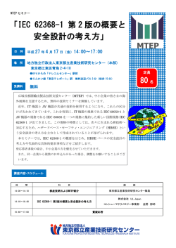
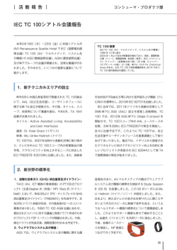
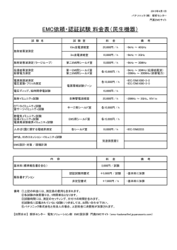
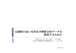
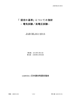
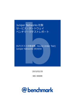
DATA SHEET > UCS 500N5 > 20140721
UCS 500N5
マルチファンクションテストジェネレーター トランジエン
ト用(EFT/バースト,サージ&電源障害) 最大5.5KV
FOR TESTS ACCORDING TO ...
> EN 300329
> EN 300340
> EN 300342-1
> EN 300386 V1.3.2
> EN 301489-1
> EN 301489-17
> EN 301489-24
> EN 301489-7
> EN 50121
> EN 55024
> EN 61000-4-11
> EN 61000-4-29
> EN 61000-4-4
> EN 61000-4-5
> EN 61000-4-8
> EN 61000-4-9
> EN 61000-6-1
> EN 61000-6-2
> FCC 97-270 (part 68)
> IEC 60255-22-5
> IEC 61000-4-11
> ...
UCS 500N5 - コンパクト試験器 EFT/バースト,サージ、電源障害
UCS 500N5ウルトラコンパクトなシミュレーターは、国際規格(基本および汎用規格)に要求されるトランジエント、電
源障害に適合できるもっとも多用途の試験器です。UCS 500N5は、自動制御された最大100Aまでの外部カップリング
ネットワークによる3相DUT試験にも拡張できる単相DUTの開発試験、イミュニティ試験やCEマーキングに適合で
きる最も経済的な試験器です。
EM TESTは、磁場テストのような様々な試験の多種のアクセサリーを提供しています。
特徴
> バーストモジュール(IEC/EN 61000-4-4)最大5.5kV
APPLICATION AREAS
INDUSTRY
BROADCAST
> 電源障害モジュール(IEC/EN 61000-4-11)
MEDICAL
RENEWABLE ENERGY
> 磁場フィールドテスト (オプションアクセサリに
よる)
RESIDENTIAL
> サージモジュール(IEC/EN 61000-4-5)最大5kV
> 内蔵単相カプラ300V/16A
TELECOM
> フロントパネルでの手動操作
> USBとGPIB-Bus リモート制御用
www.emtest.com
COMPONENTS
© EM TEST > PAGE 1/8
DATA SHEET > UCS 500N5 > 20140721
TECHNICAL DETAILS
利点
ソフトウエア
オールインワン 試験に必要な全て機能を備えています
。
IEC.CONTROL 制御とドキュメント化ソフトウエア
UCS 500N5は、試験に必要な機能をすべて備えています
。制御とDUTの主電源は、異なるDUT供給電源に対
応するために、分けられています。
UCS 500N5は、フロントパネルから手動操作が可能で、
又、内蔵USB or GPIBによってリモート制御できます。E
UTの状態によって試験シーケンスを制御することも可
能です。モニター出力(BNC)を備えて、信号測定の確認が
容易となっています。インターロック、警告ランプのよ
うな安全機能も備えています。
事前にプログラムされた標準試験ルーチンによって、試
験は大変便利なものになります。
UCS 500N5は、Quick Startテストルーチンを提供してお
り、個々のDUTの感度レベルを試験している時に、オン
ラインでパラメータ変更が可能です。
際立った便利性、わかりやすく構成されたWINDOW
と操作性、
ユーザー仕様の試験シーケンスを柔軟に構築できるEM
TEST 標準ライブラリー群は、iec.controlソフトウエアの
特徴です。そのソフトウエアは、接続されたEM TESTジェ
ネレータにそって、自動セットアップされます。充実し
たレポート機能は、国際規格に適合したテストレポート
を作成するのに役立ちます。iec.controlは、 Windows
2000, Windows XP, Windows Vista and Windows 7をサポ
ートします。リモート制御もUSB、GPIB経由で実現され
ます。iec.controlは、National Instruments製の幅広い種
類のGPIGカードをサポートします。
他のモデル
UCS 500N シリーズ コンパクト試験器 最大7KV
操作
簡単な操作
UCS 500Nウルトラコンパクト試験器はEFT/バースト,サー
ジ,電源障害に適応でき、最大電圧5.5kVと7kVの2つのモ
デルが用意されています。
フロントパネルメニューとファンクションキーによって
、試験ルーティンのプログラムを迅速かつ正確なものに
します。そのカーソルはプログラムされたルーティンの
全てのテストパラメータを迅速にコントロールします。
このようにテスト手順を簡略にすることにより、試験の
信頼性を高め、それぞれの試験ステップを正確に実行し
ます。
www.emtest.com
© EM TEST > PAGE 2/8
DATA SHEET > UCS 500N5 > 20140721
TECHNICAL DETAILS
補助デバイス
アクセサリ
CNI 503 - 3相カップリング・デカップリングネットワ
ーク バーストとサージ用
MS 100N-磁場コイル 電源周波数とパルス化磁場フィー
ルド
EM TESTは、完全自動化されたバースト、サージの3相カ
ップリング・デカップリングネットワークを提供します。
また、3相DUTにも拡張されます。そのネットワーク
の定格電流の最大は、100Aとなります。
MS 100Nは、EC/EN 61000-4-8とIEC/EN 61000-4-9に規定
される1sqm磁場コイルです。コイルの簡単に動くように
設計されています。フィールドコイルは高さ調整可能で
360°回転します。
電源周波数磁場を発生させる為に電流トランスMC2630
が使用されます。一方、100A/m以上の高磁場フィールド
には、 電流トランスMC26100を必要とします。
MV 2616 - 電動式バリアック (電圧可変)
IEC 61000-4-11に規定される電圧ディップ・瞬断、電圧変
動試験のタップ自動変圧器の代替手段として電動式バリ
アックを提供しています。電動式バリアックは自動化磁
場試験にも使用できます。
V 4780 - タップ電圧トランス (電圧ディップ、瞬断
用)
V 4780 タップトランスは、電圧ディップ、瞬断の試験に
おいて、IEC 61000-4-11 Ed.2:2004に規定される電圧を
提供するように設計されています。
V 4780S2 - タップ電圧トランス
(電圧ディップ 瞬断用)
V 4780S2 タップ自動トランスは、電圧ディップ、瞬断
の試験において、IEC 61000-4-11 Ed.2:2004に規定され
る電圧を提供するように設計されています。
手動式のV 4780と異なり、V4780S2は、選択した電圧レ
ベルによって、自動的にタップを切り替えます。
CNV 504/508 N- AND T SERIE サージカップリング・デカ
ップリングネットワーク (信号・データライン用)
CNV 504N/508N カップリング・デカップリングネット
ワークは、IEC 61000-4-5 Ed 3.0.
で規定されるI/Oライン、信号・データライン、通信ライ
ン上のサージ試験に適用できます。
www.emtest.com
HFK - 容量性カップリングクランプ
HFKは、IEC 61000-4-4.に完全準拠する容量性カップリン
グクランプ。
ITP - イミュニティテストプローブ
ITPは、開発試験用に使用されるツールです。 これはさ
まざまな電気的なフィールドプローブで構成されていま
す。このプローブによって、そのシステムまたはPCB上
の問題となる部分を特定します。ノイズ信号を生成する
為にバーストパルスが使用されます。
CA EFTキット - 検証キット EFT/バーストパルス用
IEC 61000-4-4 Ed.2の規定により、バーストジェネレータ
の特性は、2つの異なる負荷50ohmと1,000ohmによって
検証する必要があります。
EM TESTは、2つの負荷とDUT出力でパルスを検出するア
ダプタで構成するキャリブレ-ションキッドを提供します
。
CA HFK KIT - VERIFICATION KIT FOR CAPACITIVE COUPLING
CLAMP
The IEC/EN 61000-4-4 Ed 3.0 published 2012 recomends
the calibration of the capacitive coupling clamp into a
50ohm coaxial load.
The capacitive coupling clamp (HFK) is connected to the
50 ohm output of the EFT generator. A flexible insulated
plate inside the HFK is connected to a coaxial 50 ohm load
resistor for verificate the EFT / Burst wave of the capacitive
coupling clamp.
© EM TEST > PAGE 3/8
DATA SHEET > UCS 500N5 > 20140721
TECHNICAL DETAILS
ELECTRICAL FAST TRANSIENTS
ELECTRICAL FAST TRANSIENTS
BURST MODULE, EFT/N5
TEST ROUTINES
As per IEC/EN 61000-4-4 and
EN 61000-6-1, -6-2
Quick Start
On-line adjustable parameters,
easy-to-use
Test voltage
200V - 5,500V ± 10%;
100V - 2,750V ± 10% into 50ohm
Standard Test
routines
Pulse shape
5/50ns into 50ohm and 1,000ohm
As per IEC/EN 61000-4-4, Levels 1 4
As per IEC/EN 61000-6-1, -6-2
Manual Standard Test routine
Rise time tr
5ns ± 30% into 50ohm;
5ns ± 30% into 1,000ohm
User Test routines
Pulse width td
50ns ± 30% into 50ohm;
50ns -15/+100ns into 1,000ohm
Source impedance
50ohm
Polarity
Positive/negative
Synchronous burst release
Random burst release
Change voltage after T
Frequency sweep within one burst
Frequency sweep with constant
number of pulses
Frequency sweep with constant
burst duration
Change polarity after T
TRIGGER CIRCUIT
Trigger of bursts
Automatic, manual, external
Synchronization
0° - 360°, resolution 1° (16 - 500Hz)
Burst duration
td = 0.10ms - 999ms
Repetition rate
OPTIONS
HFK
Capacitive coupling clamp as per
IEC/EN 61000-4-4
tr = 10ms - 9,999ms
KW50
100:1 divider, 50ohm
Spike frequency
f = 0.1kHz - 1,000kHz
KW1000
500:1 divider, 1,000ohm
Test duration
T = 0:01min - 99:59min
T > 99:59min --> endless
CA EFT kit
Kit for burst pulse verification
consisting of KW50, KW1000 and
adapter for DUT port in a plastic case
for storage
CA HFK kit
Adapter set for capacitive coupling
clamp calibration included:
- Transducer plate as per IEC/EN
61000-4-4 Ed 3.0
- Support for positioning the KW 50
adapter on 100mm height as the
capacitive coupling clamp
CA MC F
Adapter to match KW 50 load
resistor to the EUT supply of
3-phase
N-series coupling network
A6dB
6dB attenuator, 50ohm
ITP
Immunity test probes (electrical field
generation)
ITP/H
Immunity test probe (magnetic field
generation)
OUTPUTS
Direct
Via 50ohm coaxial connector
Coupling mode
L, N, PE; all combinations
DUT supply
AC: 300V/16A; 50/60Hz
DC: 300V/16A
CRO trigger
5V trigger signal for oscilloscope
www.emtest.com
© EM TEST > PAGE 4/8
DATA SHEET > UCS 500N5 > 20140721
TECHNICAL DETAILS
COMBINATION WAVE / SURGE
COMBINATION WAVE / SURGE
SURGE MODULE, VCS/N5
TEST ROUTINES
As per IEC/EN 61000-4-5 Ed 3.0
and IEC/EN 61000-6-1, -6-2
Quick Start
One-line adjustable parameters,
easy-to-use
Voltage (o.c.)
160V - 5,000V ± 10%
Pulse front time
1.2us ± 30%
Standard Test
routines
Pulse time to half
value
50us ± 20%
As per IEC/EN 61000-4-5, Levels 1 4
As per IEC/EN 61000-6-1, -6-2
Manual Standard Test routine
User Test routines
Current (s.c.)
Max. 2,500A ± 10%
Pulse front time
8us ± 20%
Change polarity after n pulses
Change coupling after n pulses
Change voltage after n pulses
Change phase angle after n pulses
Pulse time to half
value
20us ± 20%
Pulsed Magnetic
Field
Polarity
Positive/negative/alternating
Event counter
1 - 30,000 or endless, selectable
as per IEC/EN 61000-4-9
Test levels 100, 300 and 1,000A/m
Test level steplessly adjustable under
Quick Start
OPTIONS
TRIGGER CIRCUIT
Release of pulses
Automatic, manual, external
Synchronization
0° - 360°, resolution 1°
Repetition rate
max. 1Hz (1s - 999s)
CNV504Nx
Coupling network for 4 signal/data
lines as per IEC/EN 61000-4-5 Ed 3.0
CNV508Nx
Coupling network for 8 signal/data
lines as per IEC/EN 61000-4-5 Ed 3.0
CNV 504T5
Coupling/decoupling network for
unshielded symmetrical lines
(communication lines) as per IEC/EN
61000-4-5 Ed.3 (fig. 10) for 4 lines.
CNV 508T5
Coupling/decoupling network for
unshielded symmetrical lines
(communication lines) as per IEC/EN
61000-4-5 Ed.3 (fig. 10) for 8 lines.
CNI 508N2
Assembly
Set of coupling/decoupling and
protection networks for testing
unshielded and shielded high-speed
communication lines (Ethernet lines)
IMN 2
Impedance matching adapter to
match direct output to 2ohm source
impedance
OUTPUTS
Direct
Via HV connectors for external
coupling networks
(Zi = 2ohm with optional adapter IMN
2)
Coupling mode
Line to line
Line(s) to ground
DUT supply
AC: 300V/16A; 50/60Hz
DC: 300V/16A
CRO trigger
5V trigger signal for oscilloscope
MEASUREMENTS
CRO Û-monitor
10Vp at 5,000V
CRO Î-monitor
10Vp at 2,500A
Peak voltage
5,000V in the LCD display
Peak current
2,500A in the LCD display
Overcurrent
protection
Breaks the Surge test when the surge
current is over the limit,
Limitter for differential mode,
Limitter for common mode
www.emtest.com
© EM TEST > PAGE 5/8
DATA SHEET > UCS 500N5 > 20140721
TECHNICAL DETAILS
POWER FAIL, DIPS & INTERRUPTIONS, VOLTAGE VARIATIONS
POWER FAIL, DIPS & INTERRUPTIONS, VOLTAGE VARIATIONS
POWER FAIL MODULE, PFS/N5
TEST ROUTINES
As per IEC/EN 61000-4-11,
IEC/EN 61000-4-29 and
IEC/EN 61000-6-1, -6-2
Channel PF1/PF2
AC voltage: max. 300V
AC current: max. 16A
DC voltage: max. 300V
DC current: max. 16A
Frequency
16Hz - 500Hz and DC
Switching time
< 5us into a 100ohm resistive load
Inrush current
> 500A
Protection
Both channels are protected against
short-circuit conditions.
TRIGGER CIRCUIT
Trigger of events
Automatic, manual, external
Synchronization
0° - 360°, resolution 1° (16 - 500Hz)
Repetition rate
10ms - 9,999s
Event duration
20us - 9,999s
Quick Start
On-line adjustable parameters,
easy-to-use
Standard Test
routines
As per IEC/EN 61000-4-11
for AC supplies
As per IEC/EN 61000-4-29 for DC
supplies
As per EN 61000-6-1, -6-2
Manual Standard Test routine
User Test routines
Voltage variation, control of an
external variac
Change phase angle after n events
Change event duration after n
events
Inverse mode
50/60Hz magnetic
field
As per IEC/EN 61000-4-8
Test levels 1, 3, 10 and 30A/m with
external current transformer MC
2630
Test levels 100, 300 and 1,000A/m
with external current transformer MC
26100
OPTIONS
OUTPUTS
DUT terminals
L, N and PE
CRO trigger
5V trigger signal for oscilloscope
V 4780
Tapped autotransformer as per
IEC/EN 61000-4-11 Ed.2
V 4780 S2
Tapped autotransformer as per
IEC/EN 61000-4-11 Ed.2 with
automatic change of tap
MV 2616
Motorised variac (0 - 250V, 16A)
MS 100N
Magnetic field coil, 1m x 1m
MC 2630
Current transformer for magnetic
fields up to 30A/m
MC 26100
Current transformer for magnetic
fields up to 1,000A/m
CA PFS
Calibration box for inrush current
verification as per IEC/EN 61000-4-11
MEASUREMENTS
DUT voltage
In the LCD display
DUT current
In the LCD display
MON V
Measurement of the DUT voltage;
built-in 100:1 divider
MON I
Measurement of the DUT current;
10mV/A; max. 1,000A
www.emtest.com
© EM TEST > PAGE 6/8
DATA SHEET > UCS 500N5 > 20140721
TECHNICAL DETAILS
GENERAL DATA
SPECIAL EQUIPMENT (ON REQUEST)
INTERFACES
AVAILABLE MODELS:
Serial interface
USB
UCS 500N5.1
Ultra compact simulator with EFT/N5
up to 5.5kV, VCS/N5 up to 5kV and
PFS/5; 1ph CDN 300V AC/DC (p-n) /
32A
Parallel interface
IEEE 488, addresses 1 - 30
Analog output
0 - 10VDC to control an external
transformer
CN interface
15pin SubD connector to control an
external coupling network
UCS 500N5.2
Ultra compact simulator with EFT/N5,
VCS/N5 and PFS/N5; 1ph CDN 400V
AC/DC (p-n) / 16A
Fail inputs
DUT monitoring via Fail1 and Fail2
input (one each)
UCS 500N5.3
Ultra compact simulator with EFT/5,
VCS/5 and PFS/N5;
1ph CDN 400VAC (L-N) / 32A
Dimensions
19", 3HU,
UCS 500N5.7
Weight
approx. 25kg
Ultra compact simulator with EFT/N5
and VCS/N5; 1ph CDN 300V (p-n) /
16A (but without PFS module)
UCS 500N5.8
Ultra compact simulator for EFT/N5
and PFS/N5; 1ph CDN 300V AC/DC
(p-n) / 16A
DIMENSIONS
MAINS
Supply voltage
115V/230VAC +10%/-15%
Power
approx. 75W
Frequency
50/60Hz
Fuses
2 x T 2AT (230V) or 2 x T 4AT (115V)
SAFETY
Safety standard
IEC/EN 61010
Security circuit
Control input (24VDC)
Warning lamp
Floating contact (max. 230V/6A)
ACCESSORIES INCLUDED
Mains supply
Plug depends on the country of use
DUT supply
Plug depends on the country of use
DUT adapter
Socket depends on the country of use
Operation manual,
Calibration certificate,
iec.control remote control software
OPTIONS
CNI 503Ax
3-phase coupling/decoupling
networks as per IEC/EN 61000-4-4
and -4-5 up to 200A per phase
iec.control 1
Remote control and documentation
software, including standard test
routines and reporting capabilities.
www.emtest.com
© EM TEST > PAGE 7/8
DATA SHEET > UCS 500N5 > 20140721
COMPETENCE WHEREVER
YOU ARE
CONTACT EM TEST DIRECTLY
Switzerland
USA / Canada
EM TEST (Switzerland) GmbH > Sternenhofstraße 15 > 4153 Reinach >
Switzerland
Phone +41 (0)61/7179191 > Fax +41 (0)61/7179199
Internet: www.emtest.ch > E-mail: [email protected]
AMETEK Compliance Test Solutions > 52 Mayfield Ave. > Edison > NJ 08837
Phone +1 (732) 417-0501
Internet: www.emtest.com > E-mail: [email protected]
P.R. China
Germany
EM TEST GmbH > Lünener Straße 211 > 59174 Kamen > Deutschland
Phone +49 (0)2307/26070-0 > Fax +49 (0)2307/17050
Internet: www.emtest.com > E-mail: [email protected]
E & S Test Technology Limited > Rm 913, Leftbank >
No. 68 Bei Si Huan Xi Lu > Haidian District > Beijing 100080 > P.R. China
Phone +86 (0)10 82 67 60 27 > Fax +86 (0)10 82 67 62 38
Internet: www.emtest.com > E-mail: [email protected]
France
大韓民国
EM TEST FRANCE > Le Trident - Parc des Collines > Immeuble B1 - Etage 3 >
36, rue Paul Cézanne > 68200 Mulhouse > France
Phone +33 (0)389 31 23 50 > Fax +33 (0)389 31 23 55
Internet: www.emtest.fr > E-mail: [email protected]
EM TEST Korea Limited > #405 > WooYeon Plaza > #986-8 > YoungDeok-dong >
Giheung-gu > Yongin-si > Gyeonggi-do > Korea
Phone +82 (31) 216 8616 > Fax +82 (31) 216 8616
Internet: www.emtest.co.kr > E-mail: [email protected]
Poland
EM TEST Polska > ul. Ogrodowa 31/35, 00-893 Warszawa > Polska
Phone +48 (0)518 64 35 12
Internet: www.emtest.com/pl > E-mail: [email protected]
Information about scope of delivery, visual design and technical data correspond with the state of development at time of release. Subject to
change without further notice.
www.emtest.com
© EM TEST > PAGE 8/8
© Copyright 2026 Paperzz