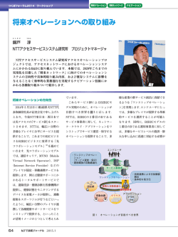
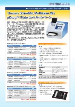
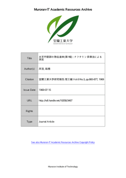
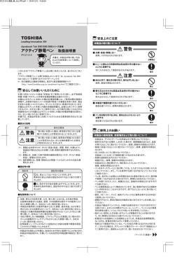
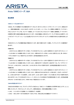
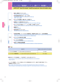
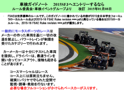
Technical Data TD
Uses(用途)
Industrial RF
Heat Equipment
(工業用高周波加熱装置)
Frequency(周波数)
40 MHz(Max.)
DC Plate Voltage(陽極電圧)
14 kV
(Max.)
Plate Dissipation(陽極損失)
35 kW
(Max.)
Output Power Class C
57 kW
TRIODE
8T61A
Water Cooling
(陽極出力)
GENERAL DATA (一般定格)
ELECTRICAL (電気的定格) :
Filament : Thoriated Tungusten (フィラメント : トリウム・タングステン)
Voltage (電圧) ····························································· 8 V
Current (電流) ························································ 280 A
Maximum Surge Current (最大瞬時電流) ··········560 A
Transconductance (Ib=2A) (相互コンダクタンス) ······················································································ 30 mS
Amplification Factor (増幅率) ················································································································ 20 -
Interelectrode Capacitances (電極間静電容量) :
Grid - Plate (グリッド-陽極) ········································································································· 33 pF
Grid - Filament (グリッド-フィラメント) ····························································································· 70 pF
Plate - Filament (陽極-フィラメント) ···························································································· 3.1 pF
Frequency for Maximum Ratings ············································································································ 40 MHz
(使用可能な最大周波数)
MECHANICAL (機械的定格) :
Overall Dimensions (外形寸法) :
Length (全長) ··································································································································· 423 ㎜
Diameter (Max.) (最大部直径) ····································································································· 138 ㎜
Mass (質量) ········································································································································ 4.7 ㎏
Mounting Position (使用位置) ·························································· Vertical Plate down(垂直陽極下)
Cooling(冷却):
Plate : Water Cooling (陽極:水冷)
Plate Dissipation (陽極損失) ·················································································· 20 28 35 kW
Min. Water Flow (最小水量) ·················································································· 34 48 65 l/min
Maximum Outlet Water Temperature (排水最高温度) ······················································· 60 ℃
Terminals : Forced Air Cooling (端子部:強制空冷)
Minimum Air Flow (最小風量) ····································································································· 1 m3/min
Maximum Tube surface temperature (最高管壁温度) ······················································· 250 ℃
Recommended Water Jacket (推奨水冷ジャケット) ······················································ TOSHIBA VT-26106
O Ring (O リング) ······························ VT-19135 ( JIS W1516-G16… I.D88.49mm,φ3.53mm)
Transfer Adapter (置換え用アダプタ) :
Filament (Inside)(フィラメント内側) ····························································· TOSHIBA VT-26115A
Filament (Outside)(フィラメント外側) ·························································· TOSHIBA VT-26116A
★The information contained herein is presented only as guide for the applications of our products. No responsibility is
assumed by TOSHIBA ELECTRON TUBES & DEVICES CO.,LTD. for any infringements of patents or other rights of the third parties
which may result from its use. No license is granted by implication or otherwise under any patent or patent rights of TOSHIBA
ELECTRON TUBES & DEVICES CO.,LTD. or others.
★The information contained herein may be changed without prior notice. It is therefore advisable to contact TOSHIBA ELECTRON
TUBES & DEVICES CO.,LTD. before proceeding with the design of equipment incorporating this product.
★この資料に掲載してある技術情報は、製品の代表的動作・応用を説明するもので、その使用に際して当社及び第三者の工業所有権そ
の他の権利に対する保証、又は実施権の許諾を行うものではありません。
★記載事項はことわりなく変更することがあります。ご使用にあたっては東芝電子管デバイス株式会社にご照会ください。
No.TEJ-8T61A
2003-12-01
8T61A
RADIO FREQUENCY POWER AMPLIFIER AND OSCILLATOR
-Class C Telegraphy(無線周波電力増幅ならびに発振 C級電信)
ABSOLUTE MAXIMUM RATINGS (絶対最大定格) :
Continuous
(連続使用)
Frequency (周波数) ·············································································································· 40 MHz
DC Plate Voltage (陽極直流電圧) ··················································································· 14 kV
DC Grid Voltage (グリッド直流電圧) ·········································································· -2000 V
DC Plate Current (陽極直流電流) ·················································································· 8.5 A
DC Grid Current (グリッド直流電流) ··············································································· 1.2 A
Plate Dissipation (陽極損失) ····························································································· 35 kW
Grid Dissipation (グリッド損失) ························································································ 800 W
TYPICAL OPERATION
(動作例) :
Continuous
(連続使用)
DC Plate Voltage (陽極直流電圧) ····················································································· 8
10 kV
DC Plate Current (陽極直流電流) ····················································································· 8
8 A
DC Grid Current (グリッド直流電流) ··············································································· 0.9
0.95 A
Grid Resistance (グリッド抵抗) ·························································································· 0.9
1.0 kΩ
Plate Output Power (陽極出力) ························································································ 40
57 kW
-2-
8T61A
DC GRID VOLTAGE Ec(V)
(グリッド直流電圧)
AVERAGE CONSTANT CURRENT CHARACTERISTICS
(平均定電流特性)
DC PLATE VOLTAGE Eb(kV)
(陽極直流電圧)
-3-
8T61A
DIMENSIONAL OUTLINE
(外 形 図)
P:Plate
(陽極)
G:Grid
(グリッド)
F:Filament
(フィラメント)
-4-
Operation and Handling
Since the power consumption of transmitting tubes is generally high, the voltages applied to each electrodes are high and
the temperature of the electrodes rises accordingly. Therefore, incorrect operation may result in personal injury. In addition, it is difficult to determine the mechanical design strength of a transmitting tube from its external appearance.
Therefore, all personnel who work with transmitting tubes must have a thorough understanding of correct operating procedures to prevent damage and must handle such tubes with extreme care.
System designers and personnel involved in performing work are responsible for ensuring worker safety.
1.
Applications and objectives
(1) This product is intended for use in industrial equipment only. It is not to be sold to or used by the general public.
(2) This product is not designed or intended for use in combination with equipment in which malfunction or incorrect operation could lead to personal injury or death, Such use is strictly prohibited.
(3) Refer to delivery specifications and engineering information issued by Toshiba to ensure safe operation of this
product.
2.
Ambient conditions
(1) Store this product in a dry location (relative humidity < 60 %). Do not store this product in a location where the
temperature or humidity may change rapidly because condensation may form on the surface of the product.
(2) A filter should be used because accumulated dust will lead to deterioration of withstand voltage and may generate smoke or catch fire.
3.
Precaution against incorrect or inappropriate operation
(1) If this product is operated with an excessively high voltage or current, X-rays exceeding the standard may be
generated. Never use this product with a voltage or current exceeding the rated values.
(2) Prior consultation with Toshiba is required if this product is to be used under conditions other than those specified or if it is used for a new type of equipment.
(3) Before using this product, determine whether or not it can be used for industrial heating applications.
(4) Only qualified engineers are permitted to use, assemble, maintain, or check this product. Other personnel are
prohibited from handling this product.
4.
Precautions for operation and maintenance
To ensure that the end user is aware of the safety precautions, include the descriptions given in the safety precautions in the operations manual provided with the equipment or take other appropriate actions.
4.1
High voltage
The voltage applied to the electrodes of the power tube can exceed 10kV, which is deadly, and the equipment
must be designed properly and operating precautions must be followed.
(1)
(2)
4.2
Safety features to be incorporated in the design
*The following safety features should be incorporated in the system design:
The equipment must be designed to prevent personnel from coming into contact with high circuit.
*Interlock switches must be provided on access doors, so that when these are opened for inspection or replacement of the tube, power supply is turned off and high-voltage capacitors are discharged.
*The power supply cannot be turned on again unless the access boor is fully closed.
Safety precautions for inspection and replacement to tube
It is preferable to request that the system manufacturer send an engineer to inspect and replace the tube; if
this is not possible, two or more qualified persons well-trained in electrical work can perform the inspection
and replacement. In either case, all power supplies must be turned off before beginning any service procedure, and parts being inspected or replaced must be grounded with aground bar.
High temperature
Although a cooling system is used, the electrode terminals are very hot both during and after operation. Do not
touch the tube just after turn off the power; wait until the temperature decreases enough not to be dangerous.
- 5 -
4.3
X-ray radiation
At voltage over 10kV, X-rays are generated. X-ray radiation at voltages up to 20kV~30kV is soft X-ray with low
penetration, therefore, it is absorbed and contained by the metal cabinet and by the glass bulb and metal parts of
the tube. However, the intensity of the radiation could become high enough to leak to the outside, adequate
evaluation of X-ray radiation for personal protection is necessary when designing the equipment.
4.4
Operating the tube
When the tube is operated for the first time or after long intermission, it is desirable to preheat for more than 15
minutes and to increase the high voltage gradually.
This operation is effective to improve and stabilize the vacuum level and ensure stable operation.
4.5
Mounting and demounting the tube
The mechanical strength of power tubes is actually fragile, even appear strong.
The internal structure of the electrodes, especially Thoriated filament, is easily affected by shock and vibration.
The mechanical strength of internal structure is same for ceramics envelope tube as that of glass envelope tube.
Therefore, careful handling is necessary for installing these tubes.
When mounting or demounting tube in the socket of equipment, special care should be taken not to subject the
tube to excess shock and vibration, such as trying to mount it into or remove it from a tight socket or by touching
the tube while it is hot.
This tube should be held vertically by holding anode or anode flange, and not to apply excess force to the terminals, etc.
4.6
Connecting the tube
The lead wires connected to the tube must be protected from vibration and thermal expansion and cooling.
There must be no force applied directly to the sealed parts.
If the connecting socket is of the wrong size, it may cause improper electric contact, fall off during operation,
damage the tube during mounting and demounting, cause degrading the cooling effect. When tightening terminals,
do not apply excessive force to the seat parts. When connecting the tubes, do not solder the leads nor attempt
connection by winding bare wires to the terminal directly as this is very dangerous. Contact Toshiba for the requirements of the proper accessory parts such as sockets, cap, etc.
4.7
Maintenance and inspection
We recommend that a record be kept for the operating conditions, and that periodic maintenance checks be performed to ensure stable operation and maximum operation life of the tube. Record voltage, current and electrode
temperature, and the cause of fluctuations, if any.
Check the operation of the safety devices such as the overload relay, water relay and air flow relay.
Confirm that the tube is mounted correctly.
Attention should also be paid to environmental conditions, as high humidity and dust may damage the external
insulation of the rube.
4.8
Storage
When the tube is to be stored for a long time, pack it in the box and store the box in a location with less vibration
and low humidity, oriented correctly as indicated.
Vibration may break the filament or the tube; high humidity may damage the insulation of the valve base and
cause poor electric contact. Do not place the bare tube directly on the floor, even when remounting the tube.
4.9
Transportation
When the tube is to be transported, pack it taking the original packing method.
Any other method may damage the tube.
- 6 -
Precaution for Safe Operation and Handling
This operation manual describes the important information for preventing injury to personnel at manufactures employing
this electron tube, users, and other personnel, as well as for preventing property loss and for ensuring safe operation.
Fully understand the meanings of following indications and symbols before reading this manual and observe all precautions for safe operation.
Keep this operation manual near the electron tube for immediate reference.
[Description of indications]
Indication
Meaning
WARNING
Indicates a potentially hazardous situation which, if not avoided, could result in death or serious
injury.
CAUTION
Indicates a potentially hazardous situation which, if not avoided, may result in minor or moderate
injury or property damage.
*1: The phase “minor or moderate injury” means personal injury, burn, electrical shock, etc. that does not require inpatient medical care.
*2: The term “property damage” means extended damage such as damage to facilities or materials.
[Description of symbols]
Symbol
“DON’T”
:
“DO”
:
Meaning
Indicates a prohibition (something that you must NOT do).
Details are described in words near the symbol.
Indicates a compulsion (something that you must do).
Details are described in words near the symbol.
[Disclaimer]
■Toshiba will not be held responsible for associated damage (loss of business profits, interruption of business,
etc.) resulting from the operation or non-availability of the equipment.
■Toshiba will not be held responsible for damage caused by natural calamities, fires, acts by the third parties,
accidents, intentional or accidental mis-operation, and operation under abnormal conditions.
■Toshiba will not be held responsible for damage caused by non-observance of the ratings of this equipment.
■Toshiba will not be held responsible for damage caused by malfunctions of the system in which this equipment is incorporated.
[Restrictions on use]
■This equipment is not designed or manufactured for use in combination with systems that include components that directly affect the maintenance or loss of human life(*1). Do not use this equipment for such systems.
*1 : Systems / equipment directly affecting the maintenance or loss of human life include the following:
・Life-support systems, surgical equipment, and diagnostic equipment
■If this equipment is used in combination with systems (*2) that are related to public safety or maintenance of
essential public services, special procedures (*3) are required for the operation, maintenance, and management of the systems. Contact Toshiba in advance.
*2 : Systems related to public safety or maintenance of essential public services include the following:
・The main control systems of nuclear power plants, safety protection systems for unclear facilities, and other
important systems for safety
・Mass-transit and air traffic control systems
*3 : Special procedures refers to the development of safe systems (fool-proof, fail-safe, and advanced design, etc.) in
close cooperation with Toshiba engineers.
[Manufacturing, installation, and operation of the equipment]
The manufacturing, installation, and operation of systems which incorporate this equipment and transmit electromagnetic waves should be performed in compliance with all applicable regulations related to electromagnetic
waves.
- 7 -
WARNING
DON’T
DISASSEMBLE
DOs
DON’Ts
■Do not disassemble, modify, or repair the equipment.
There is danger of irradiation, fire, electric shock, or burns due to high-frequency electromagnetic wave.
■Provide a protective fence preventing contact with the high-voltage section.
If you approach or touch the electrode section or lead wires while power is supplied, there is
danger of death or injury due to electric shock. The protective fence should be equipped with
safety switches that shut down the high-voltage power supply as soon as a door or panel is
opened.
■Install the waveguide and output flange sections securely, so as to prevent electromagnetic wave leakage.
There is danger of irradiation, fire, or burns due to high-frequency electromagnetic waves.
■Keep the area around the equipment free of flammable materials and keep the equipment
free of dust. Otherwise, there is danger of fire.
■Provide an X-ray protective shield if an X-ray dose exceeding 77.4 µ C/kg・h is output.
Otherwise, there is danger of X-ray exposure and the consequent health, related problems. The
protective shield should be equipped with safety switches that shut down the high-voltage power
supply as soon as a door or panel is opened.
■Provide a safety device which prevents overcurrents due to shorting between the electrode terminals etc.
Otherwise, the connection cables may be heated and there is danger of fire.
■Before performing preventive maintenance work, turn OFF the power supply and perform
grounding of each electrode to enable discharge.
Otherwise, there is danger of death or injury due to electric shock.
■Do not solder connection lead wires directly to electrode terminals and do not wind bare
wires around electrode terminals.
The connection sections become hot, and there is danger of fire, electric shock and burns.
■Do not look into the waveguide, the antenna, or the edge section of the co-axial cable
during operation.
Doing so may result in loss of eyesight due to exposure of the eyes to high-frequency electromagnetic waves.
■Persons with cardiac pacemakers must not engage in manufacturing, operation, or preventive maintenance of the equipment.
There is danger of abnormal operation of cardiac pacemakers.
CAUTION
DON’Ts
■Do not lift or carry objects with a weight of more than 20 kg on your own.
Otherwise, there is danger of back injury during lifting or injury due to falling.
During carrying-in and installation, use suitable lifting / carrying-in equipment or enlist the help of
others when carrying heavy objects.
■Do not drop the equipment or subject it to shocks.
The electron tube may break or explode and there is danger of injury.
Wear gloves and a protective mask during carrying-in and installation.
When the electron tube is disposed of, inform the disposal technicians of the danger of explosion.
■Do not touch the main body or peripheral parts during operation or, immediately after
operation is stopped.
There is danger of burns due to high temperatures.
- 8 -
使用・取扱・保管上の注意及び製品への警告表示に関して
送信管は、一般に使用する電力が大きいため、必然的に各電極に加える電圧も高くなり電極の温度も上が
ります。したがって、使用方法を誤りますと人体に危険を及ぼす可能性があります。また、外観からは送信
管の機械的強度を判断しにくいものですので管球破損等を引き起こさないよう送信管の正しい動作を知ると
同時に取扱いについても十分な配慮をしてご使用ください。
作業者の安全確保は、装置設計者及び作業関係者の責任で行ってください。
1. 用途・目的
(1) 本製品は、工業用高周波加熱装置用に限ります。一般消費者向けに販売・使用するものではありま
せん。
(2) 本製品は、その故障や誤動作が直接人命を脅かしたり、人体に危害を及ぼす恐れのある装置に使用
するため設計・意図・許可されたものではありません。
(3) 本製品の使用に当たっては、当社発行のTD(Technical Data)や Engineering information を参照
し、安全に注意してください。
2. 使用環境条件
(1) 本製品の表面に結露を生じるような急激な温度及び湿度の変化を避け、乾燥(湿度 60%以下)した
室内に保管してください。
(2) 粉塵等の汚れによる耐電圧劣化が、発煙・発火を招く恐れがありますので、フィルタの使用を推奨
します。
3. 誤使用及び不適切な使用に対する注意
(1) 異常に高い電圧・電流で使用した場合、規定値を超えるX線が放射されることがありますので、最
大定格を超えた使用は絶対しないでください。
(2) 記載範囲外で使用する場合、または、新しい形式の装置に使用する場合には問い合わせてください。
(3) 本製品の使用に当たっては、事前にその目的とする工業加熱用途に使用できるか確認してください。
(4) 本製品の使用、組立て、保守、点検は専門知識を有する技術者が取り扱い、その他の方は取り扱わ
ないでください。
4. 操作、保守に関する注意
安全に対する注意が、最終ユーザまで伝わるよう、装置の取扱説明書に盛り込む等のご配慮願います。
4.1 高
電 圧
送信管の使用電圧は、数百V~10kV 以上と非常に高いのが普通です。操作を間違えると感電事故を
起こす危険がありますので、安全装置を完備し、感電事故の防止に十分注意してください。
(1) 装置設計の場合、電源(電気回路)及び管球の高電圧部分は、動作中は触れることのできない構
造にしてください。点検や送信管の交換のときに扉やパネルを開けるときに、電源が切れ、高電
圧充電回路を放電させ、さらに扉が完全にしまった状態でないと再び電源が投入できない構造に
してください。
(2) 点検や送信管交換の場合にあたって装置を製造したメーカの技術者に依頼するのが良い方法で
すが、止むを得ない場合は、電気の専門的作業に詳しい人の、しかも二人以上での取扱いが望ま
しいです。
いずれの場合も、装置の全電源を切り、これから作業しようとする高電圧部ひとつひとつをアー
ス棒で完全にアースして進めてください。
- 9 -
4.2 高
温 度
冷却方式が何であっても、動作中はもちろん動作停止後でも、各電極端子は相当に温度が上がって
ます。電圧切断直後の作業は行わないでください。必ず危険のない温度に下がるまで待つ必要があり
ます。
4.3 X 線 放 射
X線は電圧が 10kV 程度以上になると発生しはじめますが、20~30kV までは透過力の弱い軟X線で
あるため、筐体に用いられる金属板や送信管自体の硝子容器や金属部分等で吸収され外部には、出な
いことが多いのです。しかし、X線は少なからず発生していることが考えられますので、装置の設計
の場合はX線についての評価を十分にしてください。
4.4 使 用 開 始
送信管の最初の使用の場合は、15 分間以上の予熱をすることが望ましく、高電圧も徐々に上昇する
ようにします。これは、管内の真空度を上昇させ、安定してから動作させるためで、安全に使用して
いただくために必要です。
4.5 送信管の着脱
外囲器に硝子を使用しているものはもちろん、大形の送信管は、外観上は一見非常に堅牢にみえま
すが、実際の機械的強度は弱いものです。それは内部の電極構造や特にフィラメント(トリウム・タ
ングステンフィラメント)の脆さが衝撃や振動に弱いからです。最近、外囲器が硝子からセラミック
に移行し、一見さらに堅牢になったように思われますが、内部電極の弱さに対しては、一層の注意が
必要です。
送信管を装置のソケットへ着脱する際、送信管自体へ衝撃や振動が加わらぬよう細心の注意を払っ
てください。固いソケットへの無理な着脱をするとき、重量の大きな管球を扱うとき、または温度が
下がりきらないうちに手でふれたりするときに、送信管の取扱いが粗雑になり衝撃や振動が加わるこ
とがあります。
一般に空冷管ではバルブ中央部またはベースを持ち、強制空冷管ではラジエータ・ハンドルを水冷
管では陽極または陽極のフランジをもって垂直に保持し、頭部や側部の端子に力を与えないようにし
てください。そのほか特に指定のある管球では、必ず指定されたところをもってください。
重量の大きなものは 2 人以上で扱い、手運びが困難な場合はリフトやチェンブロックのご使用をお
すすめします。
4.6 接
続
送信管へ接続用リード線は、振動、熱膨張、冷却などに考慮してさらに封止部分に直接力が加わら
ないようにしてください。接続用ソケット・キャップは、寸法が不適当ですと電気的接触不良、使用
中の脱落、着脱時の衝撃による損傷などが発生し、放熱効果も失われます。また締め付けが必要な端
子では、過度な力が封止部にかからないようにします。いかなる送信管でも、直接管球の端子に半田
付け、または裸線の巻付けなどによって接続することは、極めて危険ですから、絶対に避けてくださ
い。
東芝送信管には、それぞれの送信管に適合するソケット・キャップ、その他の付属部品を揃えてあ
りますので、お問い合わせください。
4.7 保守・点検
送信管を安定に動作させ、さらに長寿命を得るために使用状況を定期的に記録し、保守・点検を必
ず実施してください。特に、各部の電圧・電流・電極温度が変動した場合はその原因について記録し、
保護装置(過負荷リレー・水量リレー・風量リレーなど)の動作確認、装着状態と管球異常の有無を
しらべてください。また、振動・高湿・塵埃などがありますと、管球外部の絶縁を低下させることも
ありますので、環境的な要素にも十分注意してください。
- 10 -
4.8 保
管
長期にわたって保管する場合は、包装箱に入れた状態で指示された正しい方向にして、乾燥した振
動の少ないところに保管してください。湿度が高すぎると、バルブ・ベース等の絶縁を低下させたり、
接触不良を起こす原因になります。また、フィラメント断線や電極破損の原因ともなります。ソケッ
トへのさしかえなどのような場合でも、裸管のままあるいは個装の状態で、床の上に直接置かないよ
うにしてください。
4.9 輸
送
送信管を再輸送するときは、必ず元の包装(弊社標準包装)を用いてください。
それ以外の方法では送信管が破損する場合があります。
4.10 製品への警告表示に関して
電子管を組み込んだ製品を安全に取り扱うために、その製品、保用部品(電子管を含む)及び取扱
説明書には、次の該当する警告表示を行ってください。
[表示の説明]
表
示
表示の意味
警告
“誤った取扱いをすると人が死亡する、または重傷を負う可能性のあること”を示しま
す。
注意
“誤った取扱いをすると人が傷害を負う可能性、または物的損害のみが発生する可能性
のあること”を示します。
*1
*2
*1.傷害とは、治療に入院や長期の通院を要さない、けが・やけど・感電等を示します。
*2.物的損害とは、財産・資材の破損にかかわる拡大損害を示します。
[図記号の説明]
図記号
図記号の意味
禁止(してはいけないこと)を示します。
具体的な禁止内容は、図記号の近くに文章で指示します。
強制(必ずすること)を示します。
具体的な強制内容は、図記号の近くに文章で指示します。
警
分解禁止
強
禁
制
止
告
■分解・改造・修理をしないこと。
高周波電波による被爆や火災・感電・やけどの恐れがあります。
■高電圧部への接触を防止する保護囲いを設けること。
通電中の電極部やリード線に接近したり、触れたりすると、感電により死傷の恐れが
あります。また、保護囲いには扉やパネルを開放すると同時に高電圧電源を遮断する
安全スイッチを設けてください。
■電極端子に接続用リード線を直接はんだ付けしたり、裸線を巻き付けたりしないこと。
接続部が加熱し、火災・感電・やけどの恐れがあります。
- 11 -
警
告
■近くに可燃性の部材・ちり・ごみなどがないようにすること。
火災の恐れがあります。
強
制
■77.4µC/Kg・h を超えるX線を放出するものは、X線を遮蔽する防護壁を設けること。
防護壁を設けないと被爆し、X線障害の恐れがあります。また、防護壁には扉やパネ
ルを開放すると同時に、高電圧電源を遮断する安全スイッチを設けてください。
■電極端子間ショートなどの時、過電流を遮断する安全装置を設けること。
安全装置を設けないと配線材料などが過熱し、火災の恐れがあります。
禁
強
止
制
■心臓用ペースメーカーをお使いの方は、装置の製造、運転操作及び保守点検を行わな
いこと。
心臓用ペースメーカーが異常動作する恐れがあります。
■保守・点検作業は、電源を切り各電極をアースして放電されてから行うこと。
感電により死傷の恐れがあります。
注
意
■質量 20kg 以上のものは、一人で持ち上げたり運搬したりしないこと。
持ち上げたときに腰を痛めたり、落下などにより、けがをする恐れがあります。
運搬や取り付けは、運搬器具の使用や 2 人以上で作業してください。
禁
止
■落としたり衝撃を与えたりしないこと。
電子管が割れたり破裂したりして、けがをする恐れがあります。
運搬や取り付け作業のときは、手袋、顔面保護マスクを着用してください。
また、廃棄するときは廃棄物処理業者に、破裂する恐れがあることを伝えてください。
■動作中または動作停止直後の本体及びその周辺部品に触れないこと。
高温により、やけどをする恐れがあります。
5.製造物責任について
本製品の欠陥に起因して、本製品または本製品を組み込んだ御社の製品が第三者に損害を与えたことに
より、第三者から損害賠償要求がなされたとき次の事項に該当する場合は、責任を負いかねます。
(1) 本製品の使用または使用不能によって生ずる、付随的な損害(事業利益の損失、事業の中断など)に
関して弊社は一切の責任を負いません。
(2) 天災・人災・第三者の行為、その他の事故、使用者の故意または過失、その他異常な条件下での使用
により生じた損害に関して、弊社は一切責任を負いません。
(3) 当該欠陥が、本製品の改造または当社の定めた使用、保管、廃棄等に関する諸条件(本製品の取扱い
説明書、カタログ、仕様書等に記載された注意書き、警告を含むがこれに限らない)に反したことに
起因する場合。
(4) 本製品の欠陥が生命・身体に危害を及ぼす恐れの強い製品または多大な物的損害を発生させる恐れの
強い製品(原子力関係、航空宇宙関係、輸送機械関係、医療機器関係、及び各種安全装置関係等)に
本製品が使用される場合で、事前に当社の同意を得ていない場合。
(5) 組み込み機器の誤動作などから生じた損害に関して、弊社は一切の責任を負いません。
ELECTRON TUBE ENGINEERING DEPT.
電力管技術部
1385 SHIMOISHIGAMI, OTAWARA-SHI, TOCHIGI-KEN, 324-8550, JAPAN
〒324-8550 栃木県大田原市下石上1385番地
電 話 0287(26)6577
FAX 0287(26)6061
PHONE : 0287(26)6577 FAX : 0287(26)6061
© Copyright 2026 Paperzz