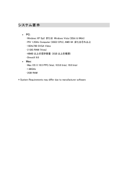
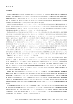
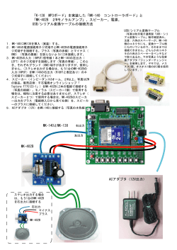
Media Bar Control Panel/Jog & Shuttle Control Panel/
Audio Control Panel/Trackball Control Panel/
Editing Control Panel
DMW-C1/C2/C3/C4/C5
電気製品は、安全のための注意事項を守らないと、
火災や人身事故になることがあります。
このインストレーションマニュアルには、事故を防ぐための重要な注意事項と
製品の取り扱いかたを示してあります。このインストレーションマニュアルを
よくお読みのうえ、製品を安全にお使いください。お読みになったあとは、いつ
でも見られるところに必ず保管してください。
(DMW-C2/C3/C5、AC アダプター PCS-AC195 用 )
本機は電源スイッチを備えていません。
設置の際には、容易にアクセスできる固定配線内に専用遮断装置を設けるか、
使用中に、容易に抜き差しできる、機器に近いコンセントに電源プラグを接続
してください。
万一、異常が起きた際には、専用遮断装置を切るか、電源プラグを抜いてくだ
さい。
XPRI DIGITAL CONTENT CREATION SYSTEM
INSTALLATION MANUAL [Japanese/English]
2nd Edition
日本語
安全のために
電気製品は、安全のための注意事項を守らないと、火災や感電などにより死亡や
大けがなど人身事故につながることがあり、危険です。
警告表示の意味
事故を防ぐために次のことを必ずお守りください。
インストレーションマニュアルお
よび製品では、次のような表示を
安全のための注意事項を守る
しています。表示の内容をよく理
解してから本文をお読みください。
3、4 ページの注意事項をよくお読みください。
定期点検をする
長期間安全に使用していただくために、定期点検を実施することをおすすめしま
す。点検の内容や費用については、ソニーのサービス担当者または営業担当者に
この表示の注意事項を守らないと、
ご相談ください。
火災や感電などにより死亡や大け
がなど人身事故につながることが
故障したら使用を中止する
あります。
ソニーのサービス担当者、または営業担当者にご連絡ください。
万一、異常が起きたら
異常な音、におい、煙が出たら
m
この表示の注意事項を守らないと、
感電やその他の事故によりけがを
したり周辺の物品に損害を与えた
a 電源を切る。
b 電源コードや接続ケーブルを抜く。
りすることがあります。
c ソニーのサービス担当者、または営業担当者に修理を依頼する。
注意を促す記号
炎が出たら
m
行為を禁止する記号
a すぐに電源を切り、消火する。
行為を指示する記号
2
目次
警告 .............................................................................. 3
注意 .............................................................................. 4
概要..................................................................................... 5
各部の名称と働き ............................................................... 5
メディアバーコントロールパネル DMW-C1........... 5
ジョグ・シャトルコントロールパネル DMW-C2.... 6
オーディオコントロールパネル DMW-C3 .............. 7
トラックボールコントロールパネル DMW-C4 ....... 9
エディティングコントロールパネル DMW-C5 ..... 10
接続................................................................................... 14
分解・改造しない
外装を外したり、改造したりすると、感
電の原因となります。
保守・運用 ........................................................................ 14
内部の調整や設定および点検を行う必要
がある場合は、必ずサービストレーニン
仕様................................................................................... 16
グを受けた技術者にご依頼ください。
事故を防ぐために、サービス
トレーニングを受けた技術者
以外はサービスを行わない
JP
機器内部に手を触れると、感電やけがの
原因となります。
内部に水や異物を入れない
水や異物が入ると火災や感電の原因とな
ることがあります。
万一、水や異物が入ったときは、すぐに
電源を切り、電源コードや接続コードを
抜いて、ソニーのサービス担当者または
営業担当者にご相談ください。
接続ケーブルを傷つけない、
はさみ込まない
接続ケーブルをはさみ込むと傷がつき、
火災や感電の原因となります。
油煙、湯気、湿気、ほこりの
多い場所では設置・使用しな
い
上記のような場所で設置・使用すると、
火災や感電の原因となります。
警告
3
電源コードのプラグおよびコ
ネクターは、突き当たるまで
しっかり差し込む
真っ直ぐに突き当たるまで差し込まない
と、火災や感電の原因となります。
指定の電源コードを使用する
指定以外の電源コードを使用すると、火
災や感電の原因となります。
インストレーションマニュアルの中で指
定されている電源コードをお使いくださ
い。
付属の AC アダプター・接続
ケーブルを使用する
指定以外の AC アダプターや接続ケーブ
ルを使用すると、火災や感電の原因とな
ります。
4
注意
製品の上にのらない、重いも
のを載せない
倒れたり、落ちたり、壊れたりして、け
がの原因となることがあります。
安定した場所に設置する
ぐらついた台の上や傾いたところなどに
設置すると、機器が落下してけがの原因
となることがあります。
概要
以下に説明する 5 つのコントロールパネルがあります。主
にノンリニア編集アプリケーションと組み合わせて使用し
ます。必要なパネルを選択して自由に配置することができ
各部の名称と働き
メディアバーコントロールパネル
DMW-C1
ます。
1 USB ケーブル
メディアバーコントロールパネル DMW-C1
素材のカラーコレクション、イコライジング、コンポジ
ティングなどのパラメーターの調整に使用します。つまみ
8 個とボタン 2 個を装備しています。
1
2
ます。
オーディオコントロールパネル DMW-C3
4
5
6
7
8
B
ジョグ・シャトルコントロールパネル
DMW-C2
VTR の動作制御や編集操作に使用します。各種制御ボタン
およびサーチダイヤルを装備しています。
電源は、DMW-C2 に付属の AC アダプターを使って供給し
3
A
2 つまみ 1 ∼ 8
3 ファンクションボタン A、B
a USB ケーブル
ジョグ・シャトルコントロールパネル、オーディオコント
ロールパネルまたはエディティングコントロールパネルに
接続します。
オーディオフェーダーとして使用します。マスターフェー
ダーと各トラック用のフェーダー 8 個の他に、ファンク
b つまみ 1 ∼ 8
ションボタンおよびミューティングボタンを装備していま
す。さらに、ヘッドホンの音量調節つまみやモニター設定
編集操作に応じて各種パラメーターの調整などに使用しま
す。
を切り換えるためのボタンも装備しています。
電源は、DMW-C3 に付属の AC アダプターを使って供給し
ます。
トラックボールコントロールパネル DMWC4
3D エフェクトのキーフレーム設定操作に使用します。ト
◆ つまみに割り付けられたパラメーターについては、XPRI/XPRI
NS のオペレーションマニュアルをご覧ください。
c ファンクションボタン A、B
各ボタンにいくつかの機能が割り付けられています。
◆ ボタンに割り付けられた機能については、XPRI/XPRI NS のオ
ペレーションマニュアルをご覧ください。
ラックボールと Z リングの他に、制御ボタンを 6 個装備し
ています。
エディティングコントロールパネル DMWC5
リニア編集機を操作する場合と同様の感覚でノンリニア編
集操作を行うためのユーザーインターフェースとして使用
します。編集作業に必要な各種操作ボタンおよびジョグダ
イヤルを装備しています。
電源は、DMW-C5 に付属の AC アダプターを使って供給し
ます。
概要 / 各部の名称と働き
5
ジョグ・シャトルコントロールパネル
DMW-C2
e ジョグ・シャトルダイヤル
ダイヤルの回転量あるいは回転角度にしたがって、コント
ロールしている VTR のテープ走行モードを切り換え、
テープを変速再生することができます。
操作パネル
f Right ( ライト ) ボタン
ファンクションボタンに割り付けた機能を実行するときや、
1 ファンクションボタン F1 ∼ F6
パラメーターの設定値を確定するときに使います。
g Left ( レフト ) ボタン
F1
F2
F3
F4
D
C
B
F5
F6
JOG
SHUTTLE
E
DMC
F
A
G
2 テープ走行制
御ボタン
このボタンとファンクションボタンを一緒に使うことによ
り、実行する機能や調整するパラメーターを切り換えます。
3 JOG/SHUTTLE /
DMC インジケーター
後面パネル
4 ファンクション
ボタン A ∼ G
5 ジョグ・シャトル
ダイヤル
DC IN
USB
UPSTREAM PORT
PORT1
PORT2
PORT3
6 Right ボタン
7 Left ボタン
a ファンクションボタン F1 ∼ F6
各ボタンにいくつかの機能が割り付けられていますが、任
3 DC IN 端子
2 USB PORT1 ∼ PORT3 端子
1 UPSTREAM PORT 端子
意の機能を割り付けることもできます。
◆ ボタンに割り付けられた機能およびボタンのカスタマイズ方法
については、XPRI/XPRI NS のオペレーションマニュアルをご
覧ください。
a UPSTREAM PORT ( アップストリームポート ) 端子
(USB)
付属の USB ケーブルを使って、XPRI/XPRI NS 本体また
b テープ走行制御ボタン
各ボタンに、VTR のテープ走行制御ボタンと同じ機能を割
は XPRI 本体に接続されたオーディオコントロールパネル
またはエディティングコントロールパネルと接続します。
り付けることができます。
c JOG ( ジョグ )/SHUTTLE ( シャトル )/DMC インジ
ケーター
コントロールしている VTR のテープ走行モードを示しま
す。
JOG インジケーターが点灯:ジョグモード
SHUTTLE インジケーター が点灯:シャトルモード
DMC インジケーターが点灯:DMC 再生モード
d ファンクションボタン A ∼ G
各ボタンにいくつかの機能が割り付けられていますが、任
意の機能を割り付けることもできます。
◆ ボタンに割り付けられた機能およびボタンのカスタマイズ方法
については、XPRI/XPRI NS のオペレーションマニュアルをご
覧ください。
6
各部の名称と働き
b USB PORT1 ∼ PORT3 (USB ポート 1 ∼ 3) 端子
(USB)
付属の USB ケーブルを使って、各種コントロールパネルを
接続することができます。
c DC IN (DC 電源入力 ) 端子
付属の AC アダプターの DC 出力端子と接続します。
オーディオコントロールパネル DMW-C3
操作パネル
3 FUNCTION /MUTING ボタン
1 ファンクションボタン 1 ∼ 8
4 OVER インジケーター
2 MUTING ボタン 1 ∼ 8
5 DATA インジケーター
FUNCTION OVER
MUTING
1
2
3
4
5
6
7
8
MONITOR LEVEL
DATA
6 MONITOR LEVELつまみ
MASTER
10
10
10
10
10
10
10
10
0
5
5
5
5
5
5
5
5
5
MINI
MAX
MONITOR
0
0
0
0
0
0
0
0
10
-5
-5
-5
-5
-5
-5
-5
-5
15
-10
-10
-10
-10
-10
-10
-10
-10
20
-30
-30
-30
-30
-30
-30
-30
-30
30
-40
-40
-40
-40
-40
-40
-40
-40
40
-45
-45
-45
-45
-45
-45
-45
-45
45
0
0
0
0
0
0
0
0
0
0
0
0
0
0
0
0
0
0
SOLO
RESET
MONO
7 MONITOR 設定部
BANK
1-4
5-8
L
R
1/5
2/6
3/7
4/5
8 MASTER フェーダー
9 チャンネルフェーダー 1 ∼ 8
a ファンクションボタン 1 ∼ 8
各ボタンにいくつかの機能が割り付けられています。
◆ ボタンに割り付けられた機能については、XPRI/XPRI NS のオ
ペレーションマニュアルをご覧ください。
b MUTING ボタン 1 ∼ 8
d OVER ( オーバー ) インジケーター
記録 / 再生オーディオ信号がレベルオーバーすると点灯し
ます。
e DATA ( データ ) インジケーター
オーディオデータが認識されると点灯します。
いずれかを押すと、MUTING ボタンのモードにしたがって
対応するトラックがミューティングされるか、またはソロ
機能(押したトラックのみ再生する)が適用されます。
f MONITOR LEVEL ( モニターレベル ) つまみ
ヘッドホンの音声のレベルを調整します(XPRI NS システ
c FUNCTION ( ファンクション )/MUTING ( ミューティ
ング ) ボタン
g MONITOR ( モニター ) 設定部
FUNCTION ボタン:各ボタンにいくつかの機能が割り付
けられています。
◆ ボタンに割り付けられた機能については、XPRI/XPRI NS
のオペレーションマニュアルをご覧ください。
MUTING ボタン:MUTING ボタンにミューティング機能
ムで使用時)。
モニター方法とモニターするトラックの選択に関する設定
を行います。
SOLO RESET ( ソロ解除 ) ボタン:ソロ機能が解除され
ます。
MONO ( モノラル ) ボタン:XPRI/XPRI NS システムのモ
ニター出力がモノラルになります。
が適用されているときは点灯し、ソロ機能が適用され
ているときは消灯します。
各部の名称と働き
7
BANK ( バンク ) ボタンとインジケーター:モニターする
h MASTER ( マスター ) フェーダー
音声信号のチャンネル 1 ∼ 4 またはチャンネル 5 ∼ 8
を選択します。
モニターチャンネル選択ボタン:BANK ボタンでチャンネ
全トラックのオーディオレベルを一律に調整します。
i チャンネルフェーダー 1 ∼ 8
音声入力ソースのチャンネルまたはタイムラインのトラッ
ル 1 ∼ 4 またはチャンネル 5 ∼ 8 を選択してから、1/
5、2/6、3/7、4/8 ボタン (L/R) でチャンネルを選択し
クのオーディオレベルを調整します。
ます。
後面パネル
1 HEADPHONES 端子
HEADPHONES
USB
UPSTREAM PORT
PORT 1
MONITOR IN
DC IN
PORT 2
PORT 3
MONITOR OUT
3 USB PORT 1 ∼ PORT 3 端子
2 DC IN 端子
4 UPSTREAM PORT 端子
5 MONITOR OUT 端子
6 MONITOR IN 端子
a HEADPHONES ( ヘッドホン ) 端子 ( ステレオ標準
ジャック )
ヘッドホンを接続して MONITOR IN 端子に入力される音
声信号をモニターできます(XPRI NS システムで使用時)。
b DC IN (DC 電源 ) 端子
付属の AC アダプターの DC OUT 端子と接続します。
c USB PORT 1 ∼ PORT 3 (USB ポート 1 ∼ 3) 端子
付属の USB ケーブルを使って、各種コントロールパネルと
接続することができます。
e MONITOR OUT ( モニター出力 ) 端子 ( ステレオミニ
ジャック )
MONITOR IN 端子への入力信号をスルーで出力します
(XPRI NS システムで使用時)。
アクティブスピーカー ( 別売り ) を接続することができま
す。HEADPHONES 端子にヘッドホンが接続されても、
オーディオ信号は MONITOR OUT 端子から出力されます。
f MONITOR IN ( モニター入力 ) 端子 ( ピンジャック、×
2)
XPRI システムの AV I/O ブロックの MON OUT L/R 端子
と接続します。
d UPSTREAM PORT ( アップストリームポート ) 端子
(USB)
付属の USB ケーブルを使って、XPRI/XPRI NS 本体また
は XPRI 本体に接続されたジョグ・シャトルコントロールパ
ネルまたはエディティングコントロールパネルと接続しま
す。
8
各部の名称と働き
トラックボールコントロールパネル
DMW-C4
1 USB ケーブル
2 ファンクションボタン A ∼ F
C
D
B
A
E
F
3 トラックボールと
Z リング
4 Right ボタン
5 Left ボタン
a USB ケーブル
ジョグ・シャトルコントロールパネル、オーディオコント
ロールパネルまたはエディティングコントロールパネルに
接続します。
b ファンクションボタン A ∼ F
各ボタンにいくつかの機能が割り付けられていますが、任
意の機能を割り付けることもできます。
◆ ボタンに割り付けられた機能およびボタンのカスタマイズ方法
については、XPRI/XPRI NS のオペレーションマニュアルをご
覧ください。
c トラックボールと Z リング
ファンクションボタン A ∼ F で選択した機能に応じて、エ
フェクトの操作や、パラメーターの調整などを行うときに
使用します。
d Right(ライト)ボタン
トラックボールと Z リングで実行した機能や、パラメー
ターの設定値を確定するときに使います。
e Left(レフト)ボタン
各種機能が割り付けられており、ファンクションボタンと
連動します。任意の機能を割り付けることもできます。
◆ ボタンに割り付けられた機能およびボタンのカスタマイズ方法
については、XPRI/XPRI NS のオペレーションマニュアルをご
覧ください。
各部の名称と働き
9
エディティングコントロールパネル DMW-C5
操作パネル
1 テンキー /FX パターン部
2 ESC/TAB/NUM LOCK ボタン
3 タイムコード部
4 ファンクションボタン部
5 トラック部
6 タイムラインエディット部
7 マスター / ソース部
qa プレイコントロール部
q; マーク部
9 SHIFT/ALL STOP/OVER WRITE/REVIEW ボタン
8 ポジション部
a テンキー /FX パターン部
す。SHIFT ボタンと併用すると、DISS(ディゾルブの
2(FX2) ∼ 9(FX9):単独では数字入力ボタンとして機能
します。使用するときは、ナムロック機能をオンにし
ます。SHIFT ボタンと併用すると、FX2 ∼ FX9 ボタ
付加)ボタンとして機能します。CTRL ボタンと併用
すると、MENU(メインメニューの呼び出し)ボタン
として機能します。
ンとして機能します。
1(FX1):単独では数字入力ボタンとして機能します。使
00(SPEED、CLOSE):単独では数字入力ボタンとして
機能します。使用するときは、ナムロック機能をオン
用するときは、ナムロック機能をオンにします。
SHIFT ボタンと併用すると、FX1 ボタンとして機能し
にします。SHIFT ボタンと併用すると、SPEED(ス
ピードコントロール)ボタンとして機能します。
ます。CTRL ボタンと併用すると、Properties(プロパ
ティーの表示)ボタンとして機能します。
CTRL ボタンと併用すると、CLOSE(ウィンドウを閉
じる)ボタンとして機能します。
0(DISS、MENU):単独では数字入力ボタンとして機能し
ます。使用するときは、ナムロック機能をオンにしま
10
各部の名称と働き
DEL(DEL FX、TB MENU):単独では削除ボタンとして
機能します。SHIFT ボタンと併用すると、DEL FX
(エフェクトの削除)ボタンとして機能します。CTRL
ボタンと併用すると、TB MENU(タスクバーメ
ニューの呼び出し)ボタンとして機能します。
ALT:機能切り換えボタンとして機能します(キーボード
f タイムラインエディット部
MATCH FRAME(REV MATCH、GANG):単独では
Match Frame(マッチフレーム)ボタンとして機能し
ます。SHIFT ボタンと併用すると、Reverse Match
の Alt キーの機能)。
− (SCL − ):単独では−記号入力ボタンとして機能しま
List(リバースマッチリスト)ボタンとして機能しま
す。CTRL ボタンと併用すると、GANG(ギャンギン
す。CTRL ボタンと併用すると、SCL −(ズームアウ
ト)ボタンとして機能します。
グ)ボタンとして機能します。
EXTRC(LIFT):単独では EXTRC(エクストラクト)ボ
+ (SCL + ):単独では+記号入力ボタンとして機能しま
す。CTRL ボタンと併用すると、SCL +(ズームイン)
タンとして機能します。SHIFT ボタンと併用すると、
LIFT(リフト)ボタンとして機能します。
ボタンとして機能します。
CTRL:機能切り換えボタンとして機能します(キーボー
EXTEND:エクステンドボタンとして機能します。
ADD EDIT:エディットの付加ボタンとして機能します。
ドの Ctrl キーの機能)
。
ENTER:エンター(確定)ボタンとして機能します。
UNDO(REDO): UNDO(元に戻す)ボタンとして機能し
ます。SHIFT ボタンと併用すると、REDO(やり直
b ESC/TAB/NUM LOCK ボタン
ESC:エスケープ(強制解除)ボタンとして機能します。
TAB:タブ入力ボタンとして機能します。
NUM LOCK:ナムロックボタンとして機能します。ナム
ロック機能がオンになっているときは、インジケー
ターが点灯します。
c タイムコード部
TC/CTL(F/TC):タイムデータの表示切り換えボタンで
す。単独では TC/CTL(タイムコード /CTL 表示)ボ
タンとして機能します。SHIFT ボタンと併用すると、
F/TC(フレーム数 / 時分秒フレーム表示)ボタンとし
て機能します。
CTL RESET:CTL リセットボタンとして機能します。
SET DUR:デュレーション設定ボタンとして機能します。
TRANS TIME:トランジションのオプション設定ボタン
として機能します。
し)ボタンとして機能します。
CUT(COPY):単独では CUT(カット)ボタンとして機
能します。SHIFT ボタンと併用すると、COPY(コ
ピー)ボタンとして機能します。
PASTE(Toggle A/B/AB Side Trim):単独では PASTE
(貼り付け)ボタンとして機能します。SHIFT ボタンと
併用すると、Toggle A/B/AB Side Trim(A サイドシン
グルトリムモード /B サイドシングルトリムモード /
デュアルトリムモード切り換え)ボタンとして機能しま
す。
TRIM:トリムモードボタンとして機能します。トリム
モードがオンになると、インジケーターが点灯します。
g マスター / ソース部
MASTR:Master Viewer にフォーカスを移動するボタン
として機能します。Master Viewer がアクティブに
なっているとき点灯します。
SRC:Source Viewer にフォーカスを移動するボタンとし
て機能します。Source Viewer がアクティブになって
d ファンクションボタン部
F1 ∼ F12 ボタンに XPRI/XPRI NS システムの各ツールの
いるとき点灯します。
P1:Logging Tool にフォーカスを移動し、Port1 を選択す
起動機能や各ツールで使用できるコマンドを任意に割り付
けし、ボタンを押すだけでツールを起動したり、機能を実
るボタンとして機能します。
P2:Logging Tool にフォーカスを移動し、Port2 を選択す
行することができます。F9 ∼ F12 ボタンは、割り付けら
れた機能がオンになっているときに、インジケーターが点
るボタンとして機能します。
灯します。
h ポジション部
e トラック部
BS:バックスペース入力ボタンとして機能します。
GOTO IN(GOTO OUT):単独では GOTO IN(マークイ
A1 ∼ A4、V1、V2、DSK:トラック選択ボタンとして
機能します。A1 ∼ A4 ボタンと SHIFT ボタンを併用
すると、A5 ∼ A8 トラック選択ボタンとして機能しま
す。A1 ∼ A4 トラックが編集作業の対象として選択さ
れている場合は、対応するボタンが点灯します。A5 ∼
A8 トラックが編集作業の対象として選択されている場
合は、A5 ∼ A8 インジケーターが点灯します。
EDIT MODE:エディットモード切り換えボタンとして機
能します。
ンへジャンプ)ボタンとして機能します。SHIFT ボタ
ンと併用すると、GOTO OUT(マークアウトへジャン
プ)ボタンとして機能します。
FS:未設定。
PREV EVENT(HOME):単独では PREV EVENT(前の
イベントへ移動)ボタンとして機能します。SHIFT ボ
タンと併用すると、HOME(ホームへ戻る)ボタンと
して機能します。
各部の名称と働き
11
R(PG UP):単独では上カーソルボタンとして機能します。
FF:早送りボタンとして機能します。
CTRL ボタンと併用すると、PG UP(ページアップ)
ボタンとして機能します。
NEXT EVENT(END):単独では NEXT EVENT(次のイ
SHTL(STOP):単独では SHTL(シャトルモード)ボタ
ンとして機能します。SHIFT ボタンと併用すると、
STOP(停止)ボタンとして機能します。
ベントへ移動)ボタンとして機能します。SHIFT ボタ
ンと併用すると、END(エンドへ進む)ボタンとして
JOG:JOG(ジョグモード)ボタンとして機能します。
ジョグモードがオンになると、ボタンが点灯します。
機能します。
T:左カーソルボタンとして機能します。
DMC:DMC(ダイナミックモーションコントロール)
モードボタンとして機能します。
r(PG DN):単独では下カーソルボタンとして機能します。
CTRL ボタンと併用すると、PG DN(ページダウン)
ジョグ / シャトルダイヤル:シャトル /DMC モードでは、
ダイヤル操作の回転角に対応したスピードで再生を行
ボタンとして機能します。
t:右カーソルボタンとして機能します。
i SHIFT/ALL STOP/OVER WRITE/REVIEW ボタン
SHIFT:左右 2 箇所あります。いずれも機能切り換えボタ
ンとして機能します(キーボードの Shift キーの機能)。
REVIEW:プリロール / レビューボタンとして機能しま
す。
OVER WRITE(SPLICE IN、REC):単独では OVER
WRITE(クリップをオーバーライトモードで Timeline
Editor に貼り付け)ボタンとして機能します。SHIFT
ボタンと併用すると、SPLICE IN(クリップをスプラ
イスインモードで Timeline Editor に貼り付け)ボタン
として機能します。CTRL ボタンと併用すると、REC
(記録)ボタンとして機能します。
ALL STOP:単独ではすべての動作を停止するボタンとし
て機能します。SHIFT ボタンと併用すると、スペース
入力ボタンとして機能します。
j マーク部
MARK IN(CLEAR IN):単独では MARK IN(イン点の設
定)ボタンとして機能します。SHIFT ボタンと併用す
ると、CLEAR IN(マークインのクリア)ボタンとし
て機能します。
MARK OUT(CLEAR OUT):単独では MARK OUT(ア
ウト点の設定)ボタンとして機能します。SHIFT ボタ
ンと併用すると、CLEAR OUT(マークアウトのクリ
ア)ボタンとして機能します。
MARK CLIP(CL I/O):単独では MARK CLIP(クリップ
のスタート / エンドをイン / アウト点として設定)ボ
タンとして機能します。SHIFT ボタンと併用すると、
CL I/O (マークイン / アウトの両方を削除)ボタンと
して機能します。
k プレイコントロール部
PLAY(STBOF):単独では PLAY(再生)ボタンとして機
能します。SHIFT ボタンと併用すると、STBOF
(VTR のスタンバイオフ)ボタンとして機能します。
STILL(EJECT):単独では STILL(静止画)ボタンとし
て機能します。SHIFT ボタンと併用すると、EJECT
(イジェクト)ボタンとして機能します。
REW:巻き戻しボタンとして機能します。
12
各部の名称と働き
います。ジョグモードでは、ダイヤル操作の回転速度
に対応したスピードで再生を行います。
シャトル / ジョグ /DMC モードがオフのときは、ダイ
ヤルを回転させてカーソルを移動することができます。
単独では上カーソルボタン、下カーソルボタンとして
機能します(R、r ボタンの機能)
。SHIFT ボタンと併
用すると、左カーソルボタン、右カーソルボタンとし
て機能します(T、t ボタンの機能)
。CTRL ボタン
と併用すると、タブを入力することができます(TAB
ボタンの機能)。
後面パネル
1 USB UPSTREAM PORT 端子
2 USB PORT1 ∼ PORT3 端子
3 DC IN 端子
a USB UPSTREAM PORT(USB アップストリーム
ポート)端子 ( シリーズ B リセプタクル )
付属の USB ケーブルを使って、XPRI/XPRI NS 本体また
は XPRI 本体に接続されたオーディオコントロールパネル
またはジョグ・シャトルコントロールパネルと接続します。
b USB PORT1 ∼ PORT3(USB ダウンストリームポー
ト 1 ∼ 3)端子(シリーズ A リセプタクル)
付属の USB ケーブルを使って、各種コントロールパネルを
接続することができます。
c DC IN(DC 電源入力)端子 (EIAJ Type5 ジャック )
付属の AC アダプターの DC OUT 端子と接続します。
各部の名称と働き
13
接続
保守・運用
接続例については、XPRI または XPRI NS のインストレー
Sonaps Unit Utility を使って、XPRI/XPRI NS 本体から各
ションマニュアルまたはセットアップガイドをご覧くださ
い。
コントロールパネルの状態を確認することができます。
接続の方法について詳しくは、ソニーのサービス担当者に
ご相談ください。
DMW-C1/DMW-C2/DMW-C3/DMWC4
ご注意
1
XPRI/XPRI NS 編集ソフトウェアを終了する。
多量のデータ転送を伴う USB 対応機器(プリンター、スト
ご注意
レージ機器など)を複数台同時に使用すると、各コント
ロールパネルの動作に影響を与える可能性があります。
編集ソフトウェアの実行中に、Sonaps Unit Utility を起
動することはできません。
2
C:¥Program Files¥Sony¥DMW¥SonapsUnit¥Bin¥
DmwPanelUtly.exe を実行する。
次のダイアログが表示されます。
XPRI/XPRI NS とコントロールパネルの通信状態を確認
するには
正常にデバイスドライバーと通信できているコントロール
パネルのボタンが有効で、ボタンの右側にファームウェア
およびデバイスドライバーのバージョンが表示されます
(図の例ではジョグ・シャトルコントロールパネル DMWC2、オーディオコントロールパネル DMW-C3、トラック
ボールコントロールパネル DMW-C4)
。
接続されていないコントロールパネルのボタンは無効で、
ボタンの右側には何も表示されません(図の例ではメディ
アバーコントロールパネル DMW-C1)
。
接続されているコントロールパネルのボタンが無効で、
バージョンが表示されない場合、そのパネルはデバイスド
ライバーと通信できない状態です。USB ケーブルの接続を
確認し、正しく接続されているにもかかわらずこの状態の
場合はソニーのサービス担当者にご連絡ください。
DMW-C5
1
14
接続 / 保守・運用
XPRI/XPRI NS 編集ソフトウェアを終了する。
ご注意
編集ソフトウェアの実行中に、Sonaps Unit Utility を起
動することはできません。
2
C:¥Program Files¥Sony¥DMW¥SonapsUnit¥Bin¥
DmwEditConpaneUtly.exe を実行する。
正常にデバイスドライバーと通信できている場合は、
次のダイアログが表示されます。
正常にデバイスドライバーと通信できていない場合は、
エラーメッセージが表示されます。
DMW-C5 が接続されているときにこのメッセージが表
示される場合は、USB ケーブルの接続を確認してくだ
さい。正しく接続されているにもかかわらずこの状態
の場合はソニーのサービス担当者にご連絡ください。
バージョン情報を表示するには
手順 2 で表示されたダイアログの[Device information]ボ
タンをクリックします。
下図のようなダイアログが表示され、API バージョン、
Device Driver バージョン、Internal Firmware バージョン、
External Firmware バージョン、Firmware 実行モード、
PLD バージョンが表示されます。
保守・運用
15
保存湿度:20% ∼ 80%
仕様
エディティングコントロールパネル DMWC5
電源
外形寸法
付属の AC アダプターから供給
360 × 62.8 × 276.6mm(幅 / 高さ / 奥行
日本国内で使用する電源コードセットは、電気用品安全
法で定める基準を満足した承認品が要求されます。
質量
き、パームレスト装着時)
3.0 kg
ソニー推奨の電源コードセットをご使用ください。
温湿度範囲
注意(DMW-C2/C3/C5)
メディアバーコントロールパネル DMW-C1
電源
外形寸法
質量
DC 5V(USB 端子より供給)
265 × 74 × 94.5mm(幅 / 高さ / 奥行き)
0.7kg
温湿度範囲
動作温度:10°C ∼ 35°C
動作湿度:20% ∼ 80% (25°C)
保存温度:− 20°C ∼+ 60°C
保存湿度:20% ∼ 80%
ジョグ・シャトルコントロールパネル
DMW-C2
電源
外形寸法
付属の AC アダプターから供給
210 × 68.3 × 264.1mm(幅 / 高さ / 奥行
質量
き、パームレスト装着時)
0.9kg
温湿度範囲
動作温度:10°C ∼ 35°C
動作湿度:20% ∼ 80% (25°C)
保存温度:− 20°C ∼+ 60°C
保存湿度:20% ∼ 80%
オーディオコントロールパネル DMW-C3
電源
付属の AC アダプターから供給
外形寸法
267 × 65.2 × 207mm(幅 / 高さ / 奥行
き)
質量
温湿度範囲
1.7 kg
動作温度:10°C ∼ 35°C
動作湿度:20% ∼ 80% (25°C)
保存温度:− 20°C ∼+ 60°C
保存湿度:20% ∼ 80%
トラックボールコントロールパネル DMWC4
電源
DC 5V(USB 端子より供給)
外形寸法
210 × 58.8 × 225.9mm(幅 / 高さ / 奥行
き、パームレスト装着時)
質量
温湿度範囲
0.7kg
動作温度:10°C ∼ 35°C
動作湿度:20% ∼ 80% (25°C)
保存温度:− 20°C ∼+ 60°C
16
仕様
動作温度:5°C ∼ 40°C
動作湿度:20% ∼ 90% (25°C)
保存温度:− 20°C ∼+ 60°C
本機の仕様および外観は、改良のため予告なく変更するこ
とがありますが、ご了承ください。
この装置は、情報処理装置等電波障害自主規制協議会
(VCCI)の基準に基づくクラス A 情報技術装置です。こ
の装置を家庭環境で使用すると電波妨害を引き起こすこと
があります。この場合には使用者が適切な対策を講ずるよ
う要求されることがあります。
お使いになる前に、必ず動作確認を行ってください。故
障その他に伴う営業上の機会損失等は保証期間中および
保証期間経過後にかかわらず、補償はいたしかねますの
でご了承ください。
重要(DMW-C2/C3/C4)
機器の名称と電気定格は、底面に表示されています。
English
WARNING
Length
Rating
To reduce the risk of fire or electric shock,
do not expose this apparatus to rain or
moisture.
To avoid electrical shock, do not open the
cabinet. Refer servicing to qualified
personnel only.
WARNING
(for DMW-C2/C3/C5, PCS-AC195 AC
Adaptor)
This unit has no power switch.
When installing the unit, incorporate a readily accessible
disconnect device in the fixed wiring, or connect the power
cord to an easily accessible socket-outlet near the unit. If
a fault should occur during operation of the unit, operate
the disconnect device to switch the power supply off, or
disconnect the power cord.
For the customers in the U.S.A.
This equipment has been tested and found to comply with
the limits for a Class A digital device, pursuant to Part 15
of the FCC Rules. These limits are designed to provide
reasonable protection against harmful interference when
the equipment is operated in a commercial environment.
This equipment generates, uses, and can radiate radio
frequency energy and, if not installed and used in
accordance with the instruction manual, may cause
harmful interference to radio communications. Operation
of this equipment in a residential area is likely to cause
harmful interference in which case the user will be
required to correct the interference at his own expense.
You are cautioned that any changes or modifications not
expressly approved in this manual could void your
authority to operate this equipment.
All interface cables used to connect peripherals must be
shielded in order to comply with the limits for a digital
device pursuant to Subpart B of Part 15 of FCC Rules.
WARNING:THIS WARNING IS APPLICABLE FOR
USA ONLY.
If used in USA, use the UL LISTED power cord specified
below.
DO NOT USE ANY OTHER POWER CORD.
Plug Cap
Cord
Parallel blade (NEMA 5-15P Configuration)
Type NISPT-2 or SPT-2, two 16 or 18 AWG
wires
Minimum 1.5m (4 ft. 11 in.), less than 2.5m
(8 ft. 3 in.)
Minimum 10 A, 125 V
Using this unit at a voltage other than 120 V may require
the use of a different line cord or attachment plug, or both.
To reduce the risk of fire or electric shock, refer servicing
to qualified service personnel.
WARNING: THIS WARNING IS APPLICABLE FOR
OTHER COUNTRIES.
1. Use the approved Power Cord (2-core mains lead)/
Appliance Connector/Plug with earthing-contacts that
conforms to the safety regulations of each country if
applicable.
2. Use the Power Cord (2-core mains lead)/Appliance
Connector/Plug conforming to the proper ratings
(Voltage, Ampere).
If you have questions on the use of the above Power Cord/
Appliance Connector/Plug, please consult a qualified
service personnel.
GB
For the customers in Europe
WARNING
This is a Class A product. In a domestic environment, this
product may cause radio interference in which case the
user may be required to take adequate measures.
For the customers in Europe
The manufacturer of this product is Sony Corporation, 17-1 Konan, Minato-ku, Tokyo, Japan.
The Authorized Representative for EMC and product
safety is Sony Deutschland GmbH, Hedelfinger Strasse
61, 70327 Stuttgart, Germany. For any service or
guarantee matters please refer to the addresses given in
separate service or guarantee documents.
This apparatus shall not be used in the residential area.
IMPORTANT (DMW-C2/C3/C4)
The nameplate is located on the bottom.
AVERTISSEMENT
Afin de réduire les risques d’incendie ou
d’électrocution, ne pas exposer cet
appareil à la pluie ou à l’humidité.
Afin d’écarter tout risque d’électrocution,
garder le coffret fermé. Ne confier
17
l’entretien de l’appareil qu’à un personnel
qualifié.
AVERTISSEMENT
(pour DMW-C2/C3/C5, l’adaptateur secteur
PCS-AC195)
Cet appareil ne possède pas d’interrupteur d’alimentation.
Lors de l’installation de l’appareil, incorporer un dispositif
de coupure dans le câblage fixe ou brancher le cordon
d’alimentation dans une prise murale facilement
accessible proche de l’appareil. En cas de problème lors du
fonctionnement de l’appareil, enclencher le dispositif de
coupure d’alimentation ou débrancher le cordon de la
prise.
VORSICHT
Um die Gefahr von Bränden oder
elektrischen Schlägen zu verringern, darf
dieses Gerät nicht Regen oder
Feuchtigkeit ausgesetzt werden.
Um einen elektrischen Schlag zu
vermeiden, darf das Gehäuse nicht
geöffnet werden. Überlassen Sie
Wartungsarbeiten stets nur qualifiziertem
Fachpersonal.
WARNUNG
AVERTISSEMENT: CET AVERTISSEMENT EST
VALABLE POUR LES AUTRES PAYS.
1.Utilisez un cordon d’alimentation (câble secteur à 2 fils)/
fiche femelle/fiche mâle conformes à la réglementation
de sécurité locale applicable.
2.Utilisez un cordon d’alimentation (câble secteur à 2 fils)/
fiche femelle/fiche mâle avec des caractéristiques
nominales (tension, ampérage) appropriées.
Pour toute question sur l’utilisation du cordon
d’alimentation/fiche femelle/fiche mâle ci-dessus,
consultez un technicien du service après-vente qualifié.
(für DMW-C2/C3/C5, Netzadapter PCSAC195)
Dieses Gerät hat keinen Netzschalter.
Beim Einbau des Geräts ist daher im Festkabel ein leicht
zugänglicher Unterbrecher einzufügen, oder das
Netzkabel muss mit einer in der Nähe des Geräts
befindlichen, leicht zugänglichen Wandsteckdose
verbunden werden. Wenn während des Betriebs eine
Funktionsstörung auftritt, ist der Unterbrecher zu betätigen
bzw. das Netzkabel abzuziehen, damit die
Stromversorgung zum Gerät unterbrochen wird.
Pour les utilisateurs en Europe
AVERTISSEMENT
Il s’agit d'un produit de Classe A. Dans un environnement
domestique, cet appareil peut provoquer des interférences
radio, dans ce cas l’utilisateur peut être amené à prendre
des mesures appropriées.
Pour les clients en Europe
Le fabricant de ce produit est Sony Corporation, 1-7-1
Konan, Minato-ku, Tokyo, Japon.
Le représentant autorisé pour EMC et la sécurité des
produits est Sony Deutschland GmbH, Hedelfinger Strasse
61, 70327 Stuttgart, Allemagne. Pour toute question
concernant le service ou la garantie, veuillez consulter les
adresses indiquées dans les documents de service ou de
garantie séparés.
Ne pas utiliser cet appareil dans une zone résidentielle.
IMPORTANT (DMW-C2/C3/C4)
La plaque signalétique se situe sous l’appareil.
18
WARNUNG: DIESE WARNUNG GILT FÜR
ANDERE LÄNDER.
1.Verwenden Sie ein zugelassenes Netzkabel (2-LeiterNetzkabel) und einen Gerätestecker, die den
Sicherheitsvorschriften des jeweiligen Landes
entsprechen, falls zutreffend.
2.Verwenden Sie ein Netzkabel (2-Leiter-Netzkabel) und
einen Gerätestecker, die den Leistungsanforderungen
(Spannung, Stromstärke) genügen.
Falls Sie Fragen zum Gebrauch des obigen Netzkabels/
Gerätesteckers haben, wenden Sie sich bitte an
qualifiziertes Kundendienstpersonal.
Für Kunden in Europa
WARNUNG
Dies ist eine Einrichtung, welche die Funk-Entstörung
nach Klasse A besitzt. Diese Einrichtung kann im
Wohnbereich Funkstörungen verursachen; in diesem Fall
kann vom Betreiber verlangt werden, angemessene
Maßnahmen durchzuführen und dafür aufzukommen.
Für Kunden in Europa
Der Hersteller dieses Produkts ist Sony Corporation, 1-7-1
Konan, Minato-ku, Tokyo, Japan.
Der autorisierte Repräsentant für EMV und
Produktsicherheit ist Sony Deutschland GmbH,
Hedelfinger Strasse 61, 70327 Stuttgart, Deutschland. Bei
jeglichen Angelegenheiten in Bezug auf Kundendienst
oder Garantie wenden Sie sich bitte an die in den separaten
Kundendienst- oder Garantiedokumenten aufgeführten
Anschriften.
Dieser Apparat darf nicht im Wohnbereich verwendet
werden.
WICHTIG (DMW-C2/C3/C4)
Das Namensschild befindet sich auf der Unterseite des
Gerätes.
19
Table of Contents
Overview ...................................................20
Names and Functions of Parts................21
DMW-C1 Media Bar Control Panel .......... 21
DMW-C2 Jog & Shuttle Control Panel ..... 21
DMW-C3 Audio Control Panel ................. 23
DMW-C4 Trackball Control Panel............ 25
DMW-C5 Editing Control Panel ............... 26
Connections..............................................29
Maintenance and Operation ....................29
Specifications ...........................................31
Overview
Five Control Panels are provided for use with nonlinear
editing applications, as described below. You can select
the panels you need and position them as required.
DMW-C1 Media Bar Control Panel
This panel has eight knobs and two buttons. You can use
them to adjust parameters for material color correction,
equalizing, compositing, and so on.
DMW-C2 Jog & Shuttle Control Panel
This panel provides function buttons and a search dial for
VTR control and editing operations.
It is powered by the AC adaptor supplied with the DMWC2.
DMW-C3 Audio Control Panel
This panel provides audio faders. It has eight faders for
audio tracks and one master fader. It also has function
buttons and muting buttons.
It is powered by the AC adaptor supplied with the DMWC3.
DMW-C4 Trackball Control Panel
This panel is used in keyframe operations for 3D effects. It
has a trackball and Z ring, and six function buttons.
DMW-C5 Editing Control Panel
This panel allows you to carry out nonlinear editing via an
intuitive interface that resembles the interface of a linear
editor. It is equipped with a jog dial and all operation
buttons needed for editing operations, and it is powered by
the AC adaptor supplied with the DMW-C5.
20
Table of Contents / Overview
Names and Functions of
Parts
DMW-C2 Jog & Shuttle Control Panel
Operation panel
DMW-C1 Media Bar Control Panel
1 Function buttons F1 to F6
1 USB cable
F1
1
2
3
4
5
6
7
F2
F3
8
F4
D
A
C
B
B
A
F5
F6
JOG
SHUTTLE
E
DMC
F
G
2 Tape transport
buttons
3 JOG/SHUTTLE/
DMC indicators
4 Function buttons A
to G
2 Knobs 1 to 8
5 Jog/shuttle dial
3 Function buttons A and B
a USB cable
Connect to the Jog & Shuttle Control Panel, the Audio
Control Panel or the Editing Control Panel.
6 Right button
7 Left button
b Knobs 1 to 8
You can use these knobs to adjust various parameters
depending on the editing operation.
Refer to the XPRI/XPRI NS Operation Manual for
information about parameters assigned to the knobs.
c Function buttons A and B
A number of functions are assigned to these buttons.
Refer to the XPRI/XPRI NS Operation Manual for
information about functions assigned to the buttons.
a Function buttons F1 to F6
These buttons have some default functions assigned to
them, but they can be customized for other functions.
Refer to the XPRI/XPRI NS Operation Manual about the
functions assigned to these buttons and for how to perform
button customization.
b Tape transport buttons
The functions of the tape transport buttons on your VTRs
can be assigned to these buttons.
c JOG/SHUTTLE/DMC indicators
These indicators light to show the tape transport mode of
the VTR being controlled.
JOG indicator lit: Jog mode
SHUTTLE indicator lit: Shuttle mode
DMC indicator lit: DMC playback mode
d Function buttons A to G
These buttons have already a number of functions assigned
to them, but they can be customized for other functions.
Refer to the XPRI/XPRI NS Operation Manual about the
functions assigned to these buttons and for how to perform
button customization.
e Jog/shuttle dial
Allows you to control variable-speed playback on a VTR
by varying the rotation speed and rotation angle of the dial.
Names and Functions of Parts
21
f Right button
Press to execute functions assigned to the function buttons
and to confirm parameter settings.
g Left button
Using this button together with the function buttons allows
you to switch between the functions to execute or
parameters to adjust.
Rear panel
DC IN
USB
UPSTREAM PORT
PORT1
PORT2
PORT3
3 DC IN connector
2 USB PORT1 to
PORT3 connectors
1 UPSTREAM PORT connector
a UPSTREAM PORT connector (USB)
Using a USB cable, connect to the XPRI/XPRI NS main
unit, or to the Audio Control Panel or the Editing Control
Panel connected to the XPRI main unit.
b USB PORT1 to PORT3 connectors (USB)
You can connect these connectors to various control panels
using USB cables.
c DC IN (DC power input) connector
Connect to the DC output connector of the supplied AC
adaptor.
22
Names and Functions of Parts
DMW-C3 Audio Control Panel
Operation panel
3 FUNCTION/MUTING buttons
1 Function buttons 1 to 8
4 OVER indicator
2 MUTING buttons 1 to 8
5 DATA indicator
FUNCTION OVER
MUTING
1
2
3
4
5
6
7
8
MONITOR LEVEL
DATA
6 MONITOR LEVEL
knob
MASTER
10
10
10
10
10
10
10
10
0
5
5
5
5
5
5
5
5
5
0
0
0
0
0
0
0
0
10
-5
-5
-5
-5
-5
-5
-5
-5
15
MAX
MINI
MONITOR
SOLO
RESET
MONO
7 Monitor setting
section
BANK
-10
-10
-10
-10
-10
-10
-10
-10
20
-30
-30
-30
-30
-30
-30
-30
-30
30
-40
-40
-40
-40
-40
-40
-40
-40
40
-45
-45
-45
-45
-45
-45
-45
-45
45
0
0
0
0
0
0
0
0
0
0
0
0
0
0
0
0
0
0
1-4
5-8
L
R
1/5
2/6
3/7
4/5
8 MASTER fader
9 Channel faders 1 to 8
a Function buttons 1 to 8
A number of functions are assigned to these buttons.
Refer to the XPRI/XPRI NS Operation Manual for
information about functions assigned to the buttons.
b MUTING buttons 1 to 8
When you press one of these buttons, the corresponding
track is muted or the solo function is applied (the only
track played is the one whose button was pressed)
according to the mode of the MUTING button.
c FUNCTION/MUTING buttons
FUNCTION button: A number of functions are assigned
to this button.
Refer to the XPRI/XPRI NS Operation Manual for
information about functions assigned to the button.
MUTING button: Lights when the muting function is
enabled, and goes out when the solo function is
enabled.
d OVER indicator
Lights to indicate that the recording or playback audio
signals are over the threshold level.
e DATA indicator
Lights when audio data is recognized.
f MONITOR LEVEL knob
Adjusts the audio level of the headphones (when used in
the XPRI NS system).
g Monitor setting section
The buttons in this section allow you to select tracks to
monitor and the monitoring method.
SOLO RESET button: Cancels the solo function.
MONO button: The monitor output from the XPRI/XPRI
NS system becomes monaural.
BANK button and indicators: For the audio signals to
monitor, selects and indicates channels 1 to 4 or 5 to 8.
Monitor channel selection buttons: After selecting
channels 1 to 4 or 5 to 8 with the BANK button, press
the 1/5, 2/6, 3/7, 4/8 buttons (L/R) to select one or
several channels.
Names and Functions of Parts
23
h MASTER fader
Uniformly adjusts the audio level of all tracks.
i Channel faders 1 to 8
Individually adjust the audio levels of the audio input
source channel or timeline track.
Rear panel
1 HEADPHONES connector
HEADPHONES
USB
UPSTREAM PORT
PORT 1
MONITOR IN
DC IN
PORT 2
PORT 3
MONITOR OUT
3 USB PORT 1 to PORT 3 connectors
2 DC IN connector
4 UPSTREAM PORT connector
5 MONITOR OUT connector
6 MONITOR IN connectors
a HEADPHONES connector (stereo phone jack)
Connect headphones to monitor the audio signals input to
the MONITOR IN connector (when used in the XPRI NS
system).
b DC IN connector
Connect to the DC OUT connector of the supplied
AC adaptor.
c USB PORT 1 to PORT 3 connectors
You can connect these connectors to various control panels
using USB cables.
d UPSTREAM PORT connector (USB)
Using a USB cable, connect to the XPRI/XPRI NS main
unit, or to the Jog & Shuttle Control Panel or the Editing
Control Panel connected to the XPRI main unit.
e MONITOR OUT connector (stereo minijack)
Outputs the signal input to the MONITOR IN connector in
a loop-through manner (when used in the XPRI NS
system). You can connect optional active speakers to this
connector. Audio signals are output to the MONITOR
OUT connector even when headphones are connected to
the HEADPHONES connector.
24
Names and Functions of Parts
f MONITOR IN connectors (RCA phono jack, 2)
Connect to the MON OUT L/R connectors of the AV I/O
Block in the XPRI system.
DMW-C4 Trackball Control Panel
1USB cable
2 Function buttons A to F
C
B
A
D
E
F
3 Trackball and
Z ring
4 Right button
5 Left button
a USB cable
Connect to the Jog & Shuttle Control Panel, the Audio
Control Panel or the Editing Control Panel.
b Function buttons A to F
These buttons have some default functions assigned to
them, but they can be customized for other functions.
Refer to the XPRI/XPRI NS Operation Manual about the
functions assigned to these buttons and for how to perform
button customization.
c Trackball and Z ring
According to the function selected with the function
buttons A to F, you can use these controls for effect
operations, parameter adjustments, and so on.
d Right button
Confirms the function that was executed or the parameter
that was adjusted with the trackball and Z ring.
e Left button
A variety of functions are assigned to this button in
combination with the function buttons. The button can be
customized for other functions.
Refer to the XPRI/XPRI NS Operation Manual about the
functions assigned to the buttons and for how to perform
button customization.
Names and Functions of Parts
25
DMW-C5 Editing Control Panel
Operation Panel
1 Numeric keypad/FX pattern section
2 ESC/TAB/NUM LOCK buttons
3 Timecode section
4 Function button section
5 Track section
6 Timeline editing section
7 Master/source section
qa Play control section
q; Mark section
9 SHIFT/ALL STOP/OVER WRITE/REVIEW buttons
8 Position section
a Numeric keypad/FX pattern section
2 (FX2) to 9 (FX9): Function as numeric input buttons
when pressed alone with the num lock function being
on. Function as FX2 to FX9 buttons when pressed
with a SHIFT button.
1 (FX1): Functions as a numeric input button when
pressed alone with the num lock function being on.
Functions as the FX1 button when pressed with a
SHIFT button. Functions as the Properties (properties
display) button when pressed with the CTRL button.
0 (DISS, MENU): Functions as a numeric input button
when pressed alone with the num lock function being
on. Functions as a DISS (add dissolve) button when
pressed with a SHIFT button. Functions as the MENU
(main menu display) button when pressed with the
CTRL button.
26
Names and Functions of Parts
00 (SPEED, CLOSE): Functions as a numeric input
button when pressed alone with the num lock function
being on. Functions as a SPEED (speed control)
button when pressed with a SHIFT button. Functions
as a CLOSE (close window) button when pressed
with the CTRL button.
DEL (DEL FX, TB MENU): Functions as a delete button
when pressed alone. Functions as a DEL FX (delete
effect) button when pressed with a SHIFT button.
Functions as a TB MENU (display taskbar menu)
button when pressed with the CTRL button.
ALT: Functions as a function switching button (like a
keyboard Alt key).
– (SCL –): Functions as a - symbol input button when
pressed alone. Functions as an SCL - (zoom out)
button when pressed with the CTRL button.
+ (SCL +): Functions as a + symbol input button when
pressed alone. Functions as an SCL + (zoom in)
button when pressed with the CTRL button.
CTRL: Functions as a function switching button (like a
keyboard Ctrl key).
ENTER: Functions as an Enter (confirmation) button.
b ESC/TAB/NUM LOCK buttons
ESC: Functions as an escape (forcible cancel) key.
TAB: Functions as a tab input key.
NUM LOCK: Functions as a number lock button. The
indicator lights when the num lock function is on.
c Timecode section
TC/CTL (F/TC): This is a time data display switch
button. Functions as a TC (timecode)/CTL button
when pressed alone. Functions as an F/TC (frame
count display/hours:minutes:seconds:frames display)
button when pressed with a SHIFT button.
CTL RESET: Functions as a CTL reset button.
SET DUR: Functions as a set duration button.
TRANS TIME: Functions as a transition option setting
button.
d Function button section
You can assign functions to the F1 to F12 buttons to allow
you to start the various tools of the XPRI /XPRI NS system
or execute tool functions with a single button press. The
indicators on the F9 to F12 buttons light when the assigned
function is on.
e Track section
A1 to A4, V1, V2, DSK: Function as track selection
buttons. The A1 to A4 buttons select tracks A5 to A8
when pressed with a SHIFT button. The
corresponding buttons light when the A1 to A4 tracks
are selected as targets of editing operations. The A5 to
A8 indicators light when the A5 to A8 tracks are
selected as targets of editing operations.
EDIT MODE: Switches the edit mode.
f Timeline editing section
MATCH FRAME (REV MATCH, GANG): Functions
as a Match Frame button when pressed alone.
Functions as a Reverse Match List button when
pressed with a SHIFT button. Functions as a GANG
(ganging) button when pressed with the CTRL button.
EXTRC (LIFT): Functions as an EXTRC (Extract)
button when pressed alone. Functions as a LIFT (Lift)
button when pressed with a SHIFT button.
EXTEND: Functions as an extend button.
ADD EDIT: Functions as an add edit button.
UNDO (REDO): Functions as an UNDO button when
pressed alone. Functions as a REDO button when
pressed with a SHIFT button.
CUT (COPY): Functions as a CUT button when pressed
alone. Functions as a COPY button when pressed with
a SHIFT button.
PASTE (Toggle A/B/AB Side Trim): Functions as a
PASTE button when pressed alone. Functions as a
Toggle A, B or AB Side Trim button (to switch
between A-side Single Trim mode, B-side Single
Trim mode and Dual Trim mode) when pressed with
a SHIFT button.
TRIM: Functions as a Trim mode button. The indicator
lights when Trim mode is on.
g Master/source section
MASTR: Functions as a button to move the focus to the
Master Viewer. Lights when the Master Viewer is
active.
SRC: Functions as a button to move the focus to the
Source Viewer. Lights when the Source Viewer is
active.
P1: Functions as a button to move the focus to the Logging
Tool and select Port1.
P2: Functions as a button to move the focus to the Logging
Tool and select Port2.
h Position section
BS: Functions as a backspace input button.
GOTO IN (GOTO OUT): Functions as a GOTO IN
(jump to Mark In) button when pressed alone.
Functions as a GOTO OUT (jump to Mark Out)
button when pressed with a SHIFT button.
FS: Currently no function is assigned.
PREV EVENT (HOME): Functions as a PREV EVENT
(move to previous event) button when pressed alone.
Functions as a HOME (back to home position) button
when pressed with a SHIFT button.
R (PG UP): Functions as an up arrow button when pressed
alone. Functions as a PG UP (Page Up) button when
pressed with the CTRL button.
NEXT EVENT (END): Functions as a NEXT EVENT
(move to next event) button when pressed alone.
Functions as an END button when pressed with a
SHIFT button.
T: Functions as a left arrow button.
r (PG DN): Functions as a down arrow button when
pressed alone. Functions as a PG DN (Page Down)
button when pressed with the CTRL button.
t: Functions as a right arrow button.
i SHIFT/ALL STOP/OVER WRITE/REVIEW
button
SHIFT: There are two SHIFT buttons (left and right).
Function as function switching buttons (like keyboard
Shift keys).
REVIEW: Functions as a preroll/review button.
OVER WRITE (SPLICE IN, REC): Functions as an
OVER WRITE button (to paste clips to the Timeline
Editor in Overwrite mode) when pressed alone.
Names and Functions of Parts
27
Functions as a SPLICE IN button (to paste clips to the
Timeline Editor in Splice-In mode) when pressed
with a SHIFT button. Functions as a REC (record)
button when pressed with the CTRL button.
ALL STOP: Functions as a button that stops all operations
when pressed alone. Functions as a space input button
when pressed with a SHIFT button.
j Mark section
MARK IN (CLEAR IN): Functions as a MARK IN (set
Mark In point) button when pressed alone. Functions
as a CLEAR IN (clear Mark In point) button when
pressed with a SHIFT button.
MARK OUT (CLEAR OUT): Functions as a MARK
OUT (set Mark Out point) button when pressed alone.
Functions as a CLEAR OUT (clear Mark Out point)
button when pressed with a SHIFT button.
MARK CLIP (CL I/O): Functions as a MARK CLIP
button (to set the start or end point of a clip as an In or
Out point) when pressed alone. Functions as a CL I/O
button (to delete both Mark In and Out points) when
pressed with a SHIFT button.
k Play control section
PLAY (STBOF): Functions as a PLAY button when
pressed alone. Functions as a STBOF (VTR standby
off) button when pressed with a SHIFT button.
STILL (EJECT): Functions as a STILL (still picture)
button when pressed alone. Functions as an EJECT
button when pressed with a SHIFT button.
REW: Functions as a rewind button.
FF: Functions as a fast forward button.
SHTL (STOP): Functions as a SHTL (shuttle mode)
button when pressed alone. Functions as a STOP
button when pressed with a SHIFT button.
JOG: Functions as a JOG (jog mode) button. The button
lights when jog mode is on.
DMC: Functions as a DMC (dynamic motion control)
mode button.
Jog/shuttle dial: In shuttle mode and DMC mode,
playback speed varies according to the angle of
rotation of the dial. In jog mode, playback speed
varies according to the speed of rotation.
When shuttle mode, jog mode, and DMC mode are
off, rotating the dial moves the cursor. The dial
functions as an up arrow button and a down arrow
button when operated alone (the same function as the
R and r buttons). It functions as a left arrow button and
a right arrow button when operated with a SHIFT
button (the same function as the T and t button). It
inputs a tab when operated with the CTRL button (the
same function as the TAB button).
Rear panel
1 USB UPSTREAM PORT connector
2 USB PORT1 to PORT3 connectors
3 DC IN connector
a USB UPSTREAM PORT connector (series B
receptacle)
Using a USB cable, connect to the XPRI/XPRI NS main
unit, or to the Audio Control Panel or Jog & Shuttle
Control Panel connected to the XPRI main unit.
b USB PORT1 to PORT3 (USB downstream ports 1
to 3) connectors (series A receptacle)
With the supplied USB cable, you can connect to various
control panels.
c DC IN (DC power input) connector (EIAJ Type 5
jack)
Connect to the DC OUT connector of the supplied AC
adaptor.
28
Names and Functions of Parts
Connections
Maintenance and
Operation
For example connections, refer to the Installation Manual
or Setup Guide of the XPRI or XPRI NS system.
Contact your Sony representative for more information
about connections.
You can use the Sonaps Unit Utility to check the status of
each control panel from the XPRI or XPRI NS main unit.
Note
DMW-C1/DMW-C2/DMW-C3/DMW-C4
Connecting several USB devices which handle large
volumes of data, such as printers or storage devices, may
affect the operation of each control panel.
1
Exit the XPRI or XPRI NS Editing Software.
Note
The Sonaps Unit Utility cannot be started while the
Editing Software is running.
2
Execute C:\Program Files\Sony\DMW\SonapsUnit\
Bin\DmwPanelUtly.exe.
The following dialog appears.
To check the status of communications between
each panel and XPRI or XPRI NS
When the communications status is normal, the button of a
connected panel is enabled and the firmware version and
the device driver version are displayed on the right of the
button (DMW-C2 Jog & Shuttle Control Panel, DMW-C3
Audio Control Panel, and DMW-C4 Trackball Control
Panel in the above example).
The button of an unconnected panel is disabled and version
information is not displayed (DMW-C1 Media Bar
Control Panel in the above example).
If the button of a connected panel is disabled and version
information is not displayed, the panel is unable to
communicate with the device driver. Make sure the USB
cable is connected correctly. Contact a Sony service
representative if this state continues even though the cable
is connected correctly.
DMW-C5
1
Exit the XPRI or XPRI NS Editing Software.
Connections / Maintenance and Operation
29
Note
The Sonaps Unit Utility cannot be started while the
Editing Software is running.
2
Execute C:\Program Files\Sony\DMW\
SonapsUnit\Bin\DmwEditConpaeUtly.exe.
When the communications status with the device
driver is normal, the following dialog appears.
If the DMW-C5 is unable to communicate with the device
driver, the following error message appears.
If the message appears when the DMW-C5 is connected,
make sure the USB cable is connected correctly. Contact a
Sony service representative if this state continues even
though the cable is connected correctly.
To display version information
Click the Device information button in the dialog
displayed in step 2.
A dialog like the one shown below appears, displaying the
API versions, the device driver version, the internal
firmware version, the external firmware version, the
firmware execution mode, and the PLD version.
30
Maintenance and Operation
Specifications
DMW-C1 Media Bar Control Panel
Power requirements
5 V DC (powered through the USB
connector)
Dimensions (w/h/d)
265 × 74 × 94.5 mm (10 1/2 × 3 × 3 3/4
inches)
Mass
0.7 kg (1 lb 8 oz)
Temperature and humidity
Operating temperature: 10°C to 35°C
(50°F to 95°F)
Operating humidity: 20% to 80% (25°C
(77°F)
Storage temperature: –20°C to +60°C
(–4°F to +140°F)
Storage humidity: 20% to 80%
DMW-C2 Jog & Shuttle Control Panel
Power requirements
Powered from the supplied AC adaptor
Dimensions (w/h/d, with palm rest)
210 × 68.3 × 264.1 mm (8 3/8 × 2 3/4 ×
10 1/2 inches)
Mass
0.9 kg (1 lb 15 oz)
Temperature and humidity
Operating temperature: 10°C to 35°C
(50°F to 95°F)
Operating humidity: 20% to 80% (25°C
(77°F)
Storage temperature: –20°C to +60°C
(–4°F to +140°F)
Storage humidity: 20% to 80%
DMW-C3 Audio Control Panel
Power requirements
Powered from the supplied AC adaptor
Dimensions (w/h/d)
267 × 65.2 × 207 mm (10 5/8 × 2 5/8 ×
8 1/4 inches)
Mass
1.7 kg (3 lb 11 oz)
Temperature and humidity
Operating temperature: 10°C to 35°C
(50°F to 95°F)
Operating humidity: 20% to 80% (25°C
(77°F)
Storage temperature: –20°C to +60°C
(–4°F to +140°F)
Storage humidity: 20% to 80%
DMW-C4 Trackball Control Panel
Power requirements
5 V DC (powered through the USB
connector)
Dimensions (w/h/d, with palm rest)
210 × 58.8 × 225.9 mm (8 3/8 × 2 3/8 × 9
inches)
Mass
0.7 kg (1 lb 8 oz)
DMW-C5 Editing Control Panel
Power requirements
Powered from the supplied AC adaptor
Dimensions (w/h/d, with palm rest)
360 × 62.8 × 276.6 mm (14 1/4 × 2 1/2 ×
11 inches)
Mass
3.0 kg (72 lb 12 oz)
Temperature and humidity
Operating temperature: 10°C to 35°C
(50°F to 95°F)
Operating humidity: 20% to 80% (25°C
(77°F)
Storage temperature: –20°C to +60°C
(–4°F to +140°F)
Design and specifications are subject to change without
notice.
Note
Always verify that the unit is operating properly before
use. SONY WILL NOT BE LIABLE FOR DAMAGES
OF ANY KIND INCLUDING, BUT NOT LIMITED
TO, COMPENSATION OR REIMBURSEMENT ON
ACCOUNT OF THE LOSS OF PRESENT OR
PROSPECTIVE PROFITS DUE TO FAILURE OF
THIS UNIT, EITHER DURING THE WARRANTY
PERIOD OR AFTER EXPIRATION OF THE
WARRANTY, OR FOR ANY OTHER REASON
WHATSOEVER.
Specifications
31
このマニュアルに記載されている事柄の著作権は当社にあ
り、説明内容は機器購入者の使用を目的としています。従っ
て、当社の許可なしに無断で複写したり、説明内容(操作、
保守等)と異なる目的で本マニュアルを使用することを禁止
します。
The material contained in this manual consists of
information that is the property of Sony
Corporation and is intended solely for use by the
purchasers of the equipment described in this
manual.
Sony Corporation expressly prohibits the
duplication of any portion of this manual or the use
thereof for any purpose other than the operation or
maintenance of the equipment described in this
manual without the express written permission of
Sony Corporation.
DMW-C1/C2/C3/C4/C5
(WW)
3-863-759-11(1)
Sony Corporation
© 2004
© Copyright 2026 Paperzz