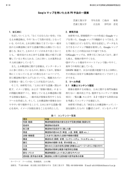
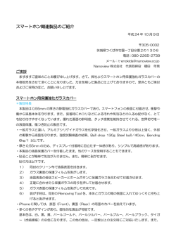
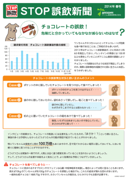
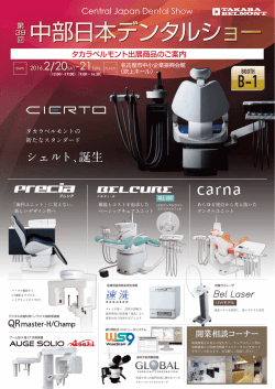
3-620-255-01(1)
アングルケースキット
取扱説明書
お買い上げいただきありがとうございます。
本
キットは、 CCD カメラモジュール XC-555/
555P 用 L アングルケースキットです。本キッ
トを装着することにより、XC-555/555Pでは
横型(HL)へのアングルの変更が可能です。
装着に関しては、お買い求めになった店にご
相談ください。お客様が本キットを装着され
た場合には保証対象外となりますので、ご注
意ください。
寸法図 [555HL]
XC-555/555P への装着
XC-555/555P への装着は、HL(横型)のみ可能で
す。縦型への変更はできません。
アングルケース A/B、ビスを使用します。
* 横型(HL)のみ可能。アングルケースの取り付
け方向、挿入方向は「アングルタイプ」を参照。
85.3
8
22
カメラケース
フロント
ブロック
22
28
96.3
単位:mm
アングルタイプ [555HL]
CCDブロックには撮像面の上を示す●印がついて
います。下図は撮像面を正面から見て●印が上と
なる場合の図です。
ディップスイッチ: 背面
XCK-L555
Sony Corporation ©2002 Printed in Japan
フレキシブルケーブル
1
本キットには、
以下の部品が含まれています。
• アングルケース A/B
• ビス[+K2 × 4:4 本]
アングルケース A
アングルケース B
カメラ本体のフロント側ネジ(+K2×2.5)4本を
はずす。
フレキシブルケーブルの反力でフロントブロッ
クが飛び出します。
ネジ(+K2×4)
ネジ(+K2×2.5)
2
アングルケース B をフロントブロック下側に
取り付ける。
3
アングルケース A をフロントブロックに取り
付ける。
4
フロントブロックをカメラケースの中に組み込
み、付属のネジ(+K2×4)4 本でしっかりと留
める。
5
手順 1 ではずしたネジ(+K2×2.5)4 本で、アン
グルケース A/B とフロントブロックをしっか
りと留める。
ご注意
フロントブロックを無理に引き出さないでくださ
い。無理に引き出すと、フレキシブルケーブルが
損傷することがあります。
ご注意
ご注意
• ネジの締め付けトルクは 0.18N・m にしてくださ
い。
• ネジは、必ず付属のネジを使ってください。
ネジの締め付けトルクは 0.18N・m にしてくださ
い。
Angle Case Kit
Instructions
XCK-L555 is an L angle case kit for the
CCD camera module, XC-555/555P. This
kit allows you to bend the XC-555/555P
90 degrees horizontally. See the
installation directions below.
The angle case kit must be installed by an
authorized dealer. Please contact the
dealer from whom you purchased the kit.
Kits installed by the user are not covered
by the warranty.
Dimensions [555HL]
Installation of XC-555/555P
You can install XC-555/555P in only HL
(horizontal) directions. VL (vertical) is not
available with this model.
Use angle case A/B and screws.
* Only horizontal (HL) direction is
available. See the above “Angle Type”
concerning with the inserting or
connecting direction.
85.3
8
22
Camera case
22
Front
block
28
96.3
UNIT: mm
Angle Type [555HL]
XCK-L555
On the upper position of the CCD block ●
is located. Set the direction correctly while
looking at the CCD block from the front so
that ● is in the upper position.
Dip switch : rear
This kit consists of the following parts.
• Angle case (A)/(B)
• Screw [+K2 × 4: 4pcs]
Angle case (A)
Angle case (B)
Flexible cable
1
Remove the four screws [+K2×2.5]
from the front panel.
The front block will pop out due to
pressure from the flexible cable.
Screw (+K2×4)
Screw (+K2×2.5)
2
Attach the angle case (B) to the
underside of the front block.
Note
Do not pull the front block out forcibly. If
you do so, you may damage the flexible
cable.
3
Attach the angle case (A) to the front
block.
4
Insert the front block into the camera
case and attach it securely with the
four screws (+K2×4) provided.
Notes
• Tighten the screws to a torque level of
0.18 N·m.
• Be sure to use the screws provided.
5
Using the four screws [+K2×2.5]
removed from the front panel in step 1,
attach the angle case (A/B) and the
front block securely.
Note
Tighten the screws to a torque level of
0.18 N·m.
© Copyright 2026 Paperzz