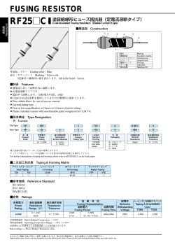
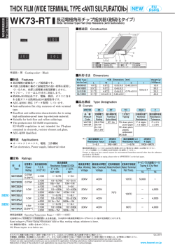
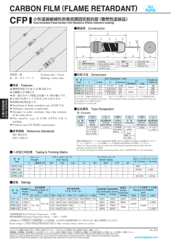
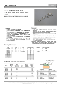
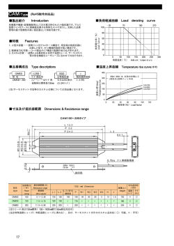
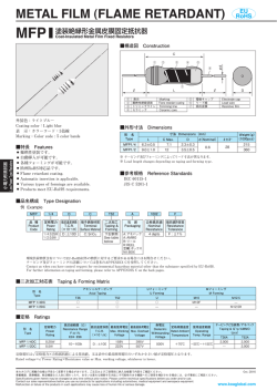
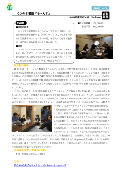
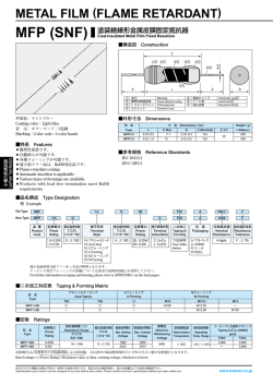
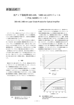
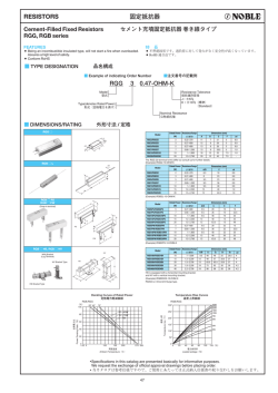
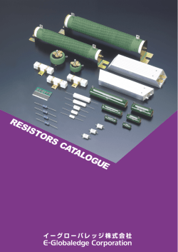
FUSING RESISTOR
RF26
EU
RoHS
塗装絶縁形ヒューズ抵抗器(L形)
Coat-insulated Fusing Resistors (L-style)
■構造図 Construction
L
②
D
③
④
⑤
h
①
⑦
⑥
0.5±0.1
H
0.3±0.05
P
外装色:ブルー Coating color:Blue
表示:カラードット Marking:Color dot
●
●
●
●
●
●
●
●
●
Electrode cap
Terminal
Resistive film
■外形寸法 Dimensions(mm)
■特長 Features
●
Insulation coating ⑤ 電極キャップ
⑥ 端子
Marking
⑦ 抵抗皮膜
Trimming line
Ceramic core
① 絶縁塗装
② 表示
③ トリミングライン
④ セラミック
通常時は抵抗器として機能します。
異
常時の過負荷に対して速やかに溶断し、回路を保護
します。
L 形フレーム(端子間隔5.08mm)を採用しております
ので、高密度実装が可能で自立強度に優れます。
難燃性塗装です。
(UV94 V-0相当)
欧州RoHS対応品です。
Function as a resistor in normal condition.
Quick fusing protects circuit from excessive overload.
H igh density mounting and excellent self-standing
strength with L-shape leads frame (lead pitch. 5.08mm).
Flame retardant coating. (Equivalent to UL94 V-0.)
P
roducts meet EU-RoHS requirement.
寸法 Dimensions(mm)
形 名
Type
L Max.
D Max.
P
H
h Max.
RF26 2E
7.25
2.54
5.08±0.3
5.0±1
5.5
Weight(g)
(1000pcs)
370
(Taping)
■参考規格 Reference Standards
IEC 60115-1
JIS C 5201-1
EIAJ RC-2125
■品名構成 Type Designation
例 Example
RF26
B
2E
T
T
A
100
J
品 種
Product
Code
抵抗温度係数
T.C.R.
(×10−6/K)
定格電力
Power
Rating
端子表面材質
Terminal
Surface Material
二次加工
Taping &
Forming
包装
Packaging
公称抵抗値
Nominal
Resistance
抵抗値許容差
Resistance
Tolerance
B:±350
2E:0.25W
T:Sn
空欄:バルク
Nil:Bulk
T:テーピング
T:Taping
空欄:バルク
Nil:Bulk
A:アモパック
A:AMMO
3 digits
J:±5%
ヒューズ抵抗器
Fusing Resistors
環境負荷物質含有についてEU-RoHS以外の物質に対するご要求がある場合にはお問合せください。
テーピングの詳細については巻末のAPPENDIX Cを参照してください。
Contact us when you have control request for environmental hazardous material other than the substance specified by EU-RoHS.
For further information on taping, please refer to APPENDIX C on the back pages.
■定格 Ratings
定格電力
Power
Rating
抵抗値範囲
Resistance
Range(Ω)
J:±5%
0.25W
0.1〜1k
(E24)
溶 断 特 性
Fusing Characteristics
溶 断 電 力
Fusing Power
テーピングと包装数
耐 電 圧
/アモパック
抵抗温度係数
Dielectric Taping & Q'ty/AMMO
T.C.R.
Withstanding
−6
(pcs)
溶断時間 (×10 /K)
Voltage
Fusing Time
T
10W
7.5W
6.25W
3.75W
3W
30sec Max.
0.1Ω〜0.18Ω 0.2Ω〜0.43Ω 0.47Ω〜0.91Ω 1.0Ω〜4.7Ω 5.1Ω〜1kΩ
±350
250V
2,000
定格周囲温度 Rated Ambient Temperature :+70℃
使用温度範囲 Operating Temperature Range :−40℃〜+155℃
定格電圧は √ ̄ ̄ ̄ ̄ ̄ ̄ ̄ ̄ ̄
定格電力×公称抵抗値による算出値となります。
Rated voltage=√ ̄ ̄ ̄ ̄ ̄ ̄ ̄ ̄ ̄ ̄ ̄ ̄
Power Rating×Resistance value
本カタログに掲載の仕様は予告なく変更する場合があります。ご注文およびご使用前に納入仕様書で内容をご確認ください。
Oct. 2016
車載機器、医療機器、航空機器など人命に関わったり、あるいは甚大な損害を引き起こす可能性のある機器へのご使用を検討される場合には、必ず事前にご相談ください。
Specifications given herein may be changed at any time without prior notice. Please confirm technical specifications before you order and/or use.
Contact our sales representatives before you use our products for applications including automotives, medical equipment and aerospace equipment.
www.koaglobal.com
Malfunction or failure of the products in such applications may cause loss of human life or serious damage.
定格電力比(%)
D
Percent rated power
100
周囲温度70℃以上で使用される場合は、左図負荷軽減曲線に従って、定
格電力を軽減して御使用ください。
For resistors operated at an ambient temperature of 70℃ or above, a power
rating shall be derated in accordance with derating curve on the left.
80
60
40
20
0
-40 -20
0 20 40 60 80 100 120 140 160
70
155
周囲温度 Ambient temperature(℃)
0.5±0.1
100
■性能 Performance
RF26B2E 0.22Ω
試験項目
Test Items
溶断時間(s)
Fusing time
30
規格値 Performance Requirements
ΔR±(%+0.05Ω)
10
試験方法
Test Methods
保証値 Limit
代表値 Typical
規定の許容差内
Within specified tolerance
—
25℃
規定値内
×15 ×20 ×25
Within specified T.C.R.
—
室温 /100℃ up
Room temperature+100℃
過負荷(短時間)
Overload(Short time)
1
0.5
定格電圧×2.5倍を5秒印加
Rated voltage×2.5 for 5s
はんだ耐熱性
Resistance to soldering heat
1
0.5
温度急変
1
Rapid change of temperature
0.5
6
抵抗値
Resistance
3
抵抗温度係数
×50
T.C.R.
1
×5 ×40 する倍率 Magnification to power rating
×10
定格電力に対する倍率 Magnification to power rating
耐湿負荷
Moisture resistance
5
70℃での耐久性
Endurance at 70℃
5
耐溶剤性
Resistance to solvent
外観に異常がなく、表示は
容易に判読できること。
—
No abnormality in appearance.
Marking shall be easily legible.
L L
難燃性
Flame retardant
−40℃
(30min.)
/+85℃
(30min.)5 cycles
80
80
2.5
40℃±2℃, 90%〜95%RH, 1000h
1.5時間 ON/0.5時間 OFFの周期 1.5h ON/0.5h OFF cycle
発炎しないこと及び自己
発炎しないこと。
No evidence of flaming or
self-flaming.
60
60
70℃±2℃, 1000h
1.5時間 ON/0.5時間 OFFの周期 1.5h ON/0.5h OFF cycle
40
40
イソプロピルアルコールに30秒間浸せきする
The resistor shall be immersed for in IPA 30 sec.
20
20
耐炎性:本体に試験火炎を15秒当て、15秒取り除く、5サイクル。
過負荷耐燃性:定格電力の2倍、4倍、8倍、16倍、32倍に相当する
電力を断線に至るまでそれぞれ1分間印加する。
Flame test : The test flame shall be applied and removed for each 15
sec respsctively to repeat the cycle 5 times.
Overload flame retardant: Power corresponding to 2, 4, 8, 16 and 32 times
the power rating shall be applied for each 1min. until disconnection
occurs.
—
00
-40
160
-40-20
-20 00 20
20 40
40 60
60 80
80100
100120
120140
140160
70
70
155
155
周囲温度 Ambient
(℃)
周囲温度 Ambienttemperature
temperature
(℃)
0.5±0.1
0.5±0.1
H
H
0.3±0.05
0.3±0.05
350℃±10℃, 3.5s±0.5s or 260℃±5℃, 10s±1s
3
D D
h h
100
100
P P
■溶断特性例 Example of Fusing Characteristics
100
100
100
100
6060
RF26B2E
0.22Ω
RF26B2E
0.22Ω
6060
溶断時間(s)
溶断時間(s)
Fusing time
Fusing time
1010
6 6
1010
6 6
×30 ×30 ×40 ×40 定格電力に対する倍率 Magnification
to to
power
rating
定格電力に対する倍率 Magnification
power
rating
×50
×50
1 1
×5 ×5 ×10
×10
×15 ×15 ×20 ×20 ×25
×25
定格電力に対する倍率 Magnification
to to
power
rating
定格電力に対する倍率 Magnification
power
rating
■使用上の注意 Precautions for Use
●
●
装塗装が難燃性特殊塗料の為、外部衝撃に比較的弱いので取り扱いにご注意ください。 洗浄は最小限にしてください。洗浄直後は
外
多少塗装膜が弱くなりますので、十分に乾燥するまで塗装膜に外力を加えないでください。乾燥後、元の強度に戻りますので、洗浄
後約20分間は抵抗器の塗装膜に外力が加わらない様に配慮ください。特に基板の積み重ね等は、行わないでください。
Be careful to handle these resistors because outer coatings are comparatively weak to outer shock due to flameproof special coats.
Please wash them to a minimum. No external force is given to the coating films until they are well dried because the coating films
become weaker right after washing. The original strength will be returned after they are dried, so please pay attention not to apply
any external force onto the coating film of resistors for 20 minutes after drying. Especially no PC boards shall be piled up.
本カタログに掲載の仕様は予告なく変更する場合があります。ご注文およびご使用前に納入仕様書で内容をご確認ください。
Oct. 2016
車載機器、医療機器、航空機器など人命に関わったり、あるいは甚大な損害を引き起こす可能性のある機器へのご使用を検討される場合には、必ず事前にご相談ください。
Specifications given herein may be changed at any time without prior notice. Please confirm technical specifications before you order and/or use.
Contact our sales representatives before you use our products for applications including automotives, medical equipment and aerospace equipment.
www.koaglobal.com
Malfunction or failure of the products in such applications may cause loss of human life or serious damage.
ヒューズ抵抗器
Fusing Resistors
3 3
3 3
1 1
×10 ×10 ×20
×20
RF26B2E
10Ω
RF26B2E
10Ω
3030
3030
溶断時間(s)
溶断時間(s)
Fusing time
Fusing time
×30 RF26B2E 10Ω
60
定格電力比(%)
定格電力比(%)
Percent rated power
Percent rated power
×20
■負荷軽減曲線 Derating Curve
© Copyright 2026 Paperzz