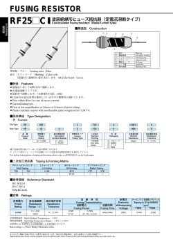
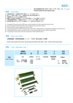
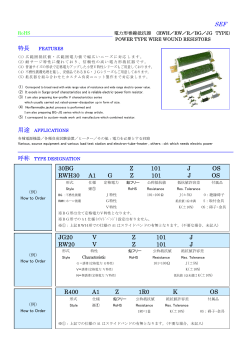
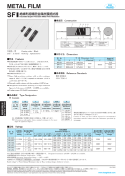
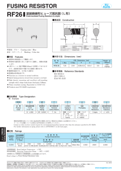
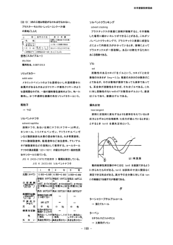
METAL FILM (FLAME RETARDANT)
MFP (SNF)
塗装絶縁形金属皮膜固定抵抗器
Coat-Insulated Metal Film Fixed Resistors
■構造図 Construction
C
②
③
④
⑤
⑥
φd
①
⑦
L
① 表示
② 難燃性絶縁塗装
③ トリミングライン
④ セラミック
D
Marking
Flame retardant coating
Trimming line
Ceramic core
⑤
⑥
⑦
電極キャップ
リード線
抵抗皮膜
Electrode cap
Lead wire
Resistive film
■外形寸法 Dimensions
外装色:ライトブルー
Coating color:Light blue
表 示:カラーコード:5色線
Marking:Color code : 5 color bands
形 名
寸 法 Dimensions(mm)
Type
L
C Max.
D
d (Nominal)
MFP1/4
6.5±0.5
7.1
2.3±0.3
0.6
MFP1/2
9.5±1.0
12.1
3.5±0.5
0.6
Weight(g)
±3
(1000pcs)
250
30
430
■特長 Features
難燃性塗装です。
自動挿入が可能です。
● 各種フォーミングが可能です。
● 端子鉛フリー品は、RoHS対応品です。
● Flame retardant coating.
● Automatic insertion is applicable.
● Various types of formings are available.
● Products with lead free termination meet RoHS
requirements.
●
■参考規格 Reference Standards
小電力形抵抗器
Low Power Type Resistors
●
IEC 60115-1
JIS C 5201-1
■品名構成 Type Designation
例 Example
Old Type
SNF
New Type
MFP
品 種
Product
Code
14
1/4
定格電力 抵抗温度係数
Power
T.C.R.
Rating (×10−6/K)
1/4:0.25W
1/2:0.5W
K
2E
D
D : ±100
端子形状
Terminal
Style
抵抗温度係数 定格電力
Power
T.C.R.
(×10−6/K) Rating
14: アキシャルリード
14: Axial lead
15: Uフォーミング
15: U Forming
16: Mフォーミング
16: M Forming
K : ±100
2E: 0.25W
2H: 0.5W
T52
A
10kΩ
F
C
T52
A
1002
F
端子表面材質
Terminal
Surface Material
二次加工
Taping &
Forming
包 装
Packaging
公称抵抗値
Nominal
Resistance
抵抗値許容差
Resistance
Tolerance
C : SnCu
L : Sn/Pb
下記参照
See table
below
A : アモパック
A : AMMO
R: リール
R: REEL
4 digits
F : ±1%
端子表面材質は鉛フリーめっき品が標準となります。
テーピング及びフォーミングの詳細については巻末のAPPENDIX Cを参照して下さい。
For further information on taping and forming, please refer to APPENDIX C on the back pages.
■二次加工対応表 Taping & Forming Matrix
アキシャルテーピング
Axial Taping
形 名
Type
Uフォーミング
U Forming
Mフォーミング
M Forming
MFP 1/4D
T26
○
T52
○
U
○
M10
M10F
M12.5
M12.5R
M15
―
MFP 1/2D
―
○
―
―
M12.5R
M15R
■定格 Ratings
形 名
Type
定格電力
Power
Rating
抵抗値範囲(Ω)
Resistance Range
F:±1%
E24・E96
抵抗温度係数
T.C.R.
(×10−6/K)
最高使用電圧
Max. Working
Voltage
MFP 1/4D
MFP 1/2D
0.25W
0.5W0
10∼100k
D : ±100
158V
223V
耐電圧
最高過負荷電圧
Dielectric
Max. Overload
Withstanding
Voltage
Voltage
395V
557V
500V
定格周囲温度
Rated Ambient
Temperature
使用温度範囲
Operating
Temp. Range
+70℃
−55℃∼+155℃
テーピングと包装数/アモパック
Taping & Q’
ty /AMMO
(pcs)
T26A
T52A
2,000
―
2,000
2,000
定格電圧は √
定格電力×公称抵抗値による算出値、又は表中の最高使用電圧のいずれか小さい値が定格電圧となります。
 ̄ ̄ ̄ ̄ ̄ ̄ ̄ ̄ ̄
Rated voltage=√ ̄ ̄ ̄ ̄ ̄ ̄ ̄ ̄ ̄ ̄ ̄ ̄
Power Rating×Resistance value or Max. working voltage, whichever is lower.
本カタログに掲載の仕様は予告なく変更する場合があります。御注文及び御使用前に、納入仕様書などで内容を御確認下さい。
Specifications given herein may be changed at any time without prior notice. Please confirm technical specifications before you order and/or use.
www.koanet.co.jp
■負荷軽減曲線 Derating Curve
定格電力比(%)
Percent rated power
100
80
60
40
20
0
-60
-40 -20
-55
0
20 40 60 80 100 120 140 160
70
155
周囲温度 Ambient temperature (℃)
周囲温度70℃以上で使用される場合は、上図負荷軽減曲線に従って、定
格電力を軽減して御使用下さい。
For resistors operated at an ambient temperature of 70℃ or above, a power
rating shall be derated in accordance with the above derating curve.
■性能 Performance
試験項目
Test Items
規格値 Performance Requirements
ΔR±
(%+0.05Ω)
試験方法
Test Methods
代表値 Typical
抵抗値
Resistance
規定の許容差内
Within specified tolerance
―
25℃
抵抗温度係数
T.C.R.
規定値内
Within specified T.C.R.
―
室温 / 100℃ up
Room temperature+100℃
過負荷(短時間)
Overload(Short time)
0.5
0.3
定格電圧 × 2.5 倍又は最高過負荷電圧の低い方を 5 秒印加
Rated voltage × 2.5 or Max. overload vol., whichever is lower, for 5s
はんだ耐熱性
Resistance to soldering heat
0.75
0.5
260℃±5℃, 10s±1s
端子強度
Terminal strength
リード線の外れ、端子のユルミのないこと。
―
No lead-coming off and loose terminals
Twist 360°
, 5 times
温度急変
Rapid change of temperature
1
0.75
−55℃
(30min.)
/+125℃
(30min.)5 cycles
耐湿負荷
Moisture resistance
5
3
40℃±2℃, 90%∼95%RH, 1000h
1.5時間 ON / 0.5時間 OFFの周期 1.5h ON / 0.5h OFF cycle
70℃での耐久性
Endurance at 70℃
3
2
70℃±2℃, 1000h
1.5時間 ON / 0.5時間 OFFの周期 1.5h ON / 0.5h OFF cycle
■使用上の注意 Precautions for Use
本製品及び実装したプリント基板にフラックス等によるイオン性不純物質が付着していると、耐湿性・耐腐食性等の点から好ましく
ありません。フラックス内には、塩素・酸等のイオン性物質が含まれている場合があります。これらのイオン性物質を除去するため
には洗浄を行って下さい。特に鉛フリーはんだを御使用の場合、濡れ性向上の為、イオン性物質を多く含有している場合があります。
RMA系のはんだ又はフラックスをご使用になるか、十分な洗浄を行って下さい。また、保管環境や実装条件・環境等によって、汗、
塩等のイオン性物質を付着させた場合も、耐湿性・耐腐食性等の点から好ましくありません。その汚染時に対しましてもこれらのイ
オン性物質を除去するために洗浄を行って下さい。
● 外装塗装が難燃性特殊塗料の為、外部衝撃に比較的弱いので取り扱いにご注意下さい。洗浄は最小限にして下さい。洗浄直後は多少
塗装膜が弱くなりますので、十分に乾燥するまで塗装膜に外力を加えないで下さい。乾燥後、元の強度に戻りますので、洗浄後約20
分間は抵抗器の塗装膜に外力が加わらない様に配慮下さい。特に基板の積み重ね等は、行わないで下さい。
● Ionic impurities such as flux etc. that are attached to these products or those mounted onto a PCB, negatively affect their moisture
resistance, corrosion resistance, etc. The flux may contain ionic substances like chlorine, acid, etc. Please wash them to get rid of these
ionic substances especially when using lead-free solder that may contain much of the said substances for improving a wetting
characteristic. Using RMA solder or RMA flux, or well-washing is needed. Also, attaching ionic substances such as perspiration, salt etc.
by storage environments or mounting conditions/environments negatively affects their moisture resistance, corrosion resistance etc.
Please wash them to remove the ionic substances when they are polluted.
● Be careful to handle these resistors because outer coatings are comparatively weak to outer shock due to flameproof special coats. Please
wash them to a minimum. No external force is given to the coating films until they are well dried because the coating films become weaker
right after washing. The original strength will be returned after they are dried, so please pay attention not to apply any external force onto
the coating film of resistors for 20 minutes after drying. Especially no PC boards shall be piled up.
●
本カタログに掲載の仕様は予告なく変更する場合があります。御注文及び御使用前に、納入仕様書などで内容を御確認下さい。
Specifications given herein may be changed at any time without prior notice. Please confirm technical specifications before you order and/or use.
www.koanet.co.jp
小電力形抵抗器
Low Power Type Resistors
保証値 Limit
© Copyright 2026 Paperzz