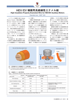
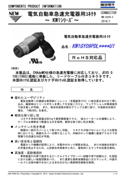
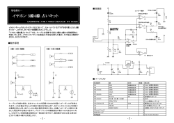
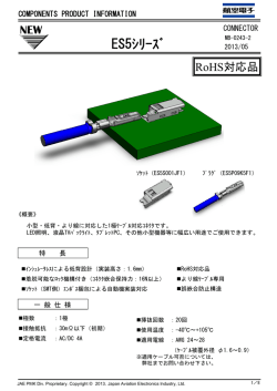
2012/02/20
DCF-S-0126-1
Japan Aviation Electronics Industry, Ltd.
Connector Div. Production Engineering Dept.
Number
番号
日本航空電子工業株式会社コネクタ事業部生産技術部
Spec:for
Original issued 初版制定:
TITLE 表題:
Operation manual for CT150-4-ES5
Page
T700316
1/11
5.Aug.2011
Rev.
Date
CN-No.
Prep
Chkd
Appd
2
17.Feb.2012
001849
T.OOKAWA
K.KOIDE
H.AKIMOTO
手動圧着工具 CT150-4-ES5 取扱説明書
ISSUED 作成元
Production Engineering Dept. 生産技術部
Prepared
Checked
Approved
PL Approved
T.OOKAWA
K.KOIDE
S.SHIMIZU
T.ABE
手動圧着工具 CRIMPING HAND TOOL
CT150-4-ES5
取扱説明書
OPERATION MANUAL
この度は、弊社の手動圧着工具をお買い上げいただき、
ありがとうございます。本工具は予め被覆を剥いた電線
とコンタクトを圧着するための手動工具です。良好な圧着
結線のため、本書の内容を十分に理解し、正しい作業を
安全に行うようお願いします。
JAE Connector Div. Proprietary.
Copyright (C) 2011, Japan Aviation Electronics Industry, Ltd.
Thank you for purchasing our crimping hand tool .This
tool is used for crimping stripped wires to contacts. To
obtain excellent crimped wires ,be sure to read this
manual carefully in order to fully understand this tool
and operate it correctly.
DCF-S-0126-2
Page
Japan Aviation Electronics Industry, Ltd.
Connector Div. Production Engineering Dept.
Number
番号
日本航空電子工業株式会社コネクタ事業部生産技術部
はじめにお読みください
T700316
2/11
READ IN THE BEGINING
絵表示について
Caution symbols
この取扱説明書及び製品への表示では、製品を
安全に正しくお使いいただき、あなたや他の人々
への危険や財産への損害を未然に防止するた
めに、色々な絵表示を記載しています。その表
示と意味は次のようになっています。内容を良く
理解してから本文をお読みください。
In this manual and on our products as well, the
following caution symbols are used to show
important information and warnings for correct
use of our products. This is to avoid possible
personal injury and property damage. Be sure
to read and understand these special instructions
before proceeding to the procedural details.
危険
DANGER
この表示を無視して誤った取り扱いをすると、人が死亡または重傷を負う危険が差し迫
って生じることが想定される内容を示しています。
A danger indicates an operation that results in serious personal injury or fatal
wound if precautions are not followed.
警告
WARNING
この表示を無視して誤った取り扱いをすると、人が死亡または重傷を負う可能性が想
定される内容を示しています。
A warning indicates an operation that could cause serious personal injury or fatal
wound if precautions are not followed.
注意
CAUTION
この表示を無視して誤った取り扱いをすると、人が傷害を負う可能性が想定される内
容及び物的損害のみの発生が想定される内容を示しています。
A caution indicates an operation that could cause personal injury or equipment
damage if precautions are not followed.
絵表示の例
Examples of caution symbols
An equilateral triangle △ serves the
same as CAUTION (or DANGER and
WARNING).It contains a specific warning
information inside (the lightning flash with
arrowhead symbol shown left means a
risk of electric shock to persons).
indicates an action
記号は禁止の行為であることを告げるもの A no entry mark
です。図の中や近傍に具体的な禁止内容(左 that must be prohibited. Inside or near it
is indicated a special instruction (the label
図の場合は分解禁止)が描かれています
shown left means prohibition of
disassembly).
△記号は注意(危険、警告を含む)を促す内
容があることを告げるものです。
図の中に具体的な注意内容(左図の場合は
感電注意)が描かれています。
●記号は行為を強制したり、指示する内容を
告げるものです。図の中に具体的な指示内容
(左図の場合は差し込みプラグをコンセントか
ら抜いてください)が描かれています。
JAE Connector Div. Proprietary.
Copyright (C) 2011, Japan Aviation Electronics Industry, Ltd.
A black circle ● indicates a required
action that must be proceeded without
failure. It contains specific instructions
inside (the label shown left means
required disconnection of a plug from an
outlet).
DCF-S-0126-2
Japan Aviation Electronics Industry, Ltd.
Connector Div. Production Engineering Dept.
日本航空電子工業株式会社コネクタ事業部生産技術部
Page
Number
番号
T700316
3/11
使用上のご注意 ATTENTION OF HANDLING
警告
WARNING
■本取扱説明書に記載されている事以外の改造
や調整は、破損や不良の原因になりますので絶対
に止めて下さい。万が一異常を感じたり、破損した
場合はお買い上げの販売店もしくは弊社カスタマ
ーサポート部門に修理依頼して頂きます様お願い
致します。
■Don’t repair or adjust,without the procedure
specified with this operation manual ,it cause
is to brake the tool or product the rejeccted
items.If you feel the tool abnormally or brake
the tool, prease inqire our shop or customer
support ,and repair it.
■本工具を長時間使用するときは、十分な休息を
取りながら作業を行ってください。身体に傷害を及
ぼすことがあります。
■Please work while getting enough rest when
you use this tool for a long time. Injury might
be caused for the body.
注意
CAUTION
■クリンパが開閉します。クリンパとアンビルの間
の隙間に指を入れないで下さい。怪我の原因とな
ります。
■ Crimper and anvil can pinch the
fingers.Never put the fingers into space
between crimper and anvil.
■指定された適合コンタクト及び適合電線以外の
ものを圧着しないで下さい。
■ハンドルは圧着完了位置でラチェトの爪が外れ
開放されるよう調整してありますので、それ以外の
状態で無理にハンドルを開放しないで下さい
■Do not crimp other than specified applicable
contacts and applicable wires.
■Do not force to open the handle except at
the position where crimp is completed. The
ratchet of the handles is adjusted to be
released at the position where the crimp is
completed.
■Lubrication to the crimp portion (anvil and
crimper) of the tool is not necessary.
■ Please check the crimp height of the
contact if the value is within the crimp height
spec, when you use the tool.
■工具の圧着部(クリンパ、アンビル)には、注油
の必要は有りません。
■工具の使用に際しては、コンタクトのクリンプハ
イトが所定の条件を満足しているか確認して下さ
い。
JAE Connector Div. Proprietary.
Copyright (C) 2011, Japan Aviation Electronics Industry, Ltd.
DCF-S-0126-2
Japan Aviation Electronics Industry, Ltd.
Connector Div. Production Engineering Dept.
日本航空電子工業株式会社コネクタ事業部生産技術部
Page
Number
番号
T700316
4/11
目次 CONTENTS
絵表示の説明・・・・・・・・・・・・・・・・・・・・・・・・・
使用上のご注意・・・・・・・・・・・・・・・・・・・・・・・・
目次・・・・・・・・・・・・・・・・・・・・・・・・・・・・・・・・・
1.仕様・・・・・・・・・・・・・・・・・・・・・・・・・・・・・・・
2.各部名称・・・・・・・・・・・・・・・・・・・・・・・・・・・
3.圧着準備・・・・・・・・・・・・・・・・・・・・・・・・・・・
4.圧着前作業・・・・・・・・・・・・・・・・・・・・・・・・・
4-1.クリンパのセット・・・・・・・・・・・・・・・・
4-2.クリンパのセット変更・・・・・・・・・・・・
5.圧着作業・・・・・・・・・・・・・・・・・・・・・・・・・・・・
5-1.ハンドルの開放・・・・・・・・・・・・・・・・・
5-2.コンタクトのセット・・・・・・・・・・・・・・・
5-3.電線のセット・・・・・・・・・・・・・・・・・・・・
5-4.圧着・・・・・・・・・・・・・・・・・・・・・・・・・・・
5-5.コンタクトの取り出し・・・・・・・・・・・・
6.製品チェック・・・・・・・・・・・・・・・・・・・・・・・・・
7.保守・点検とトラブル時の対応・・・・・・・・
7-1.清掃方法・・・・・・・・・・・・・・・・・・・・・・・
7-2.保管方法・・・・・・・・・・・・・・・・・・・・・・
7-3.修理・・・・・・・・・・・・・・・・・・・・・・・・・・・
7-4.トラブル時の対応・・・・・・・・・・・・・・
8.圧着条件・・・・・・・・・・・・・・・・・・・・・・・・・・・
8-1.適用電線とコンタクト・・・・・・・・・・・・
8-2.圧着詳細・・・・・・・・・・・・・・・・・・・・・・・
CAUTION SYMBOLS・・・・・・・・・・・・・・・・・・・・・・・・・・・・・
ATTENTION OF HANDLING・・・・・・・・・・・・・・・・・・・・・・・・・
CONTENTS・・・・・・・・・・・・・・・・・・・・・・・・・・・・・・・・・・・・・
1.SPECIFICATION・・・・・・・・・・・・・・・・・・・・・・・・・・・・・・・
2.PARTS NAME・・・・・・・・・・・・・・・・・・・・・・・・・・・・・・・・・・・
3.PREPARATION OF CRIMPING・・・・・・・・・・・・・・・・・・
4.BEFORE CRIMPING・・・・・・・・・・・・・・・・・・・・・・・・・・・
4-1.Set Of Crimper・・・・・・・・・・・・・・・・・・・・・・・・・・・・
4-2.Set Change Of Crimper・・・・・・・・・・・・・・・・・・・・・
5.CRIMPING・・・・・・・・・・・・・・・・・・・・・・・・・・・・・・・・・・・・
5-1.Handles Opening・・・・・・・・・・・・・・・・・・・・・・・・・・
5-2.Contact Setting・・・・・・・・・・・・・・・・・・・・・・・・・・・
5-3.Wire Setting・・・・・・・・・・・・・・・・・・・・・・・・・・・・・・
5-4.Crimping・・・・・・・・・・・・・・・・・・・・・・・・・・・・・・・・・
5-5.Contact Removal・・・・・・・・・・・・・・・・・・・・・・・・・
6.CHECK OF CRIMPED CONTACTS・・・・・・・・・・・・・・
7. MAINTENANCE&TROUBLE SHOOTING・・・・・・・
7-1.Cleaning・・・・・・・・・・・・・・・・・・・・・・・・・・・・・・・・・・
7-2.Strage・・・・・・・・・・・・・・・・・・・・・・・・・・・・・・・・・・・・
7-3.Repair・・・・・・・・・・・・・・・・・・・・・・・・・・・・・・・・・・・・
7-4.Trouble Shooting・・・・・・・・・・・・・・・・・・・・・・・・・・
8.CRIMPING CONDITION・・・・・・・・・・・・・・・・・・・・・・・・
8-1.Applicable Wire&Contacts・・・・・・・・・・・・・・・・・・
8-2.Crimping Data・・・・・・・・・・・・・・・・・・・・・・・・・・・・・
JAE Connector Div. Proprietary.
Copyright (C) 2011, Japan Aviation Electronics Industry, Ltd.
2
3
4
5
5
6
6
6
7
7
7
8
8
8
8
9
10
10
10
10
10
11
11
11
DCF-S-0126-2
Page
Japan Aviation Electronics Industry, Ltd.
Connector Div. Production Engineering Dept.
Number
番号
日本航空電子工業株式会社コネクタ事業部生産技術部
T700316
5/11
1.SPECIFICATION
1.仕様
工具型式
MODEL
重量
WEIGHT
サイズ
SIZE
CT150-4-ES5
約 0.7kg
About 0.7kg
W55×D20×H230(mm)
使用環境
Environment
温度 0℃~40℃(結露しないこと)
Temperature 0℃~40℃(No do be dewy. )
握力
The grip
300N
注意
CAUTION
本工具を使用するためには、300N以上の握力が必要となります。
This hand tool needs the grip of 300N or more.
2.PARTS NAME
2.各部名称
締付ナット
Lock Nut
被覆クリンパ(H)
Insulation Crimper (H)
芯線クリンパ
Wire Crimper (S)
圧着部表示
Crimper indication
位置決めストッパ
Positioning Stopper
取付ピン
Setting Pin
コンタクトガイド
Contact Guide
被覆アンビル
Insulation Anvil
JAE Connector Div. Proprietary.
Copyright (C) 2011, Japan Aviation Electronics Industry, Ltd.
合いマーク
Index Mark
芯線アンビル
Wire Anvil
DCF-S-0126-2
Page
Japan Aviation Electronics Industry, Ltd.
Connector Div. Production Engineering Dept.
Number
番号
日本航空電子工業株式会社コネクタ事業部生産技術部
②
※
6/11
3.PREPARATION OF CRIMPING
3.圧着準備
①
T700316
予め電線の被覆を指定剥き長さ(L寸法)で
剥いてください。(8項参照)
芯線の切断、傷がないことを確認し、先端
の乱れは作業前に矯正して下さい。
芯線の切断、傷があったもの、先端の乱れ
が矯正できないものは使用しないで下さ
い。
①
圧着条件については、8 項.圧着条件を参照
してください。
※
傷
芯線の乱れ
切断
Disordered wire strand
Cut off
×
②
Crack
×
不良
Fail
Strip the insulation of a wire to the specified
length“L”.(refer to para.8)
Check that each wire conductor is not damaged
nor scratched. Set any disarrayed conductors
straight prior to the crimping operation. Don't
use one with cutoff and the crack in the wick
line and the one that the disorder of the point
cannot be corrected.
Refer to 8. the crimping condition about the
condition of crimping.
×
不良
Fail
不良
Fail
○
良品
Pass
4.BEFORE CRIMPING
4.圧着前作業
4-1.クリンパのセット
4-1.Set Of Crimper
① 芯線クリンパは上下に 2 種類の圧着部があ
ります。適切な電線に合わせてセットして
下さい。
※ 芯線クリンパの外側に指示された電線サイ
ズと合うように芯線クリンパと被覆クリン
パをセットして下さい。
② クリンパに付いている合いマークでセット
状態を確認します。合いマークと工具の本体
に付いている線番表示が合っている場所が
現在のセット状態です。
① The wire crimper has two kinds of crimp cavities
up and down sides. Set it up according to the
applicable wire.
※ Set up the wire crimper and the insulation
crimper together with the wire size of the wire
crimper indication out side.
② Make sure to put the marks of the wire crimper
and insulation crimper together.
被覆クリンパ(黒色)
Insulation Crimper
合いマーク
Index mark
JAE Connector Div. Proprietary.
Copyright (C) 2011, Japan Aviation Electronics Industry, Ltd.
芯線クリンパ
Wire Crimper
線番表示
Wire size indication
DCF-S-0126-2
Page
Japan Aviation Electronics Industry, Ltd.
Connector Div. Production Engineering Dept.
Number
番号
日本航空電子工業株式会社コネクタ事業部生産技術部
T700316
4-2.クリンパのセット変更
4-2. Set Change Of Crimper
①
芯線クリンパ、被覆クリンパは、締付ナッ
トを外し、取付ピンを抜くことにより取り
外せます。使用する電線に適合する位置に
芯線クリンパをセットして下さい。
①
*
芯線クリンパ、被覆クリンパの順番や表裏
を間違えないように取り付けて下さい。
被覆クリンパが手前になります。クリンパ
は表示(被覆“H”及び線種サイズ、芯線
“S”及び線種サイズ)が外側になるよう
にセットして下さい。
取付ピンを挿入し、電線押えと共に、締付
ナットを手で締めて完了です。(締付ナッ
トは、手で締める程度で十分です。)
*
②
②
7/11
Unscrew the lock nut and take off the setting
pin to remove the wire crimper and the
insulation crimper. Fix the appropriate side of
the wire crimper in the tool body for the
applicable wire before operating this tool.
Make sure the procedure of setting up the wire
crimper and Insulation crimper or their tops.
Set up the Insulation crimper (color: black) in
front side of this tool. Set up the index mark
(Insulation crimper ”H” & wire size, Wire
crimper ”S” & wire size) is outside of this tool.
Insert the setting pin into the wire clamper and
the tool body. Then fasten the lock nut.(Lock
nut is able to fasten manually)
締付ナット
Lock Nut
芯線クリンパ表示側
Wire Crimper
indication side
取付ピン
Setting Pin
被覆クリンパ表示側
Insulation Crimper
indication side
5.CRIMPING
5.圧着作業
5-1.Handles Opening
5-1.ハンドルの開放
① コンタクトを工具に挿入する前にハンド
ルを開放状態にして下さい。
※ ハンドルが開かない場合は、ラチェットが
開放されるまでハンドルを握り締めて下
さい。
①
Open the handles before inserting a contact.
※
In case the handle does not open, close the
handles until ratchet released.
開放
OPEN
注意
CAUTION
アンビルが開閉します。怪我の原因となりますので、
クリンパとアンビルの間の隙間に指を入れないで下さい。
The crimper moves OPEN / CLOSE.
Never put fingers into opening between the crimper and anvil.
JAE Connector Div. Proprietary.
Copyright (C) 2011, Japan Aviation Electronics Industry, Ltd.
DCF-S-0126-2
Page
Japan Aviation Electronics Industry, Ltd.
Connector Div. Production Engineering Dept.
Number
番号
日本航空電子工業株式会社コネクタ事業部生産技術部
T700316
8/11
5-2.Contact Setting
5-2.コンタクトのセット
① 100~150mm程度に切断したリール状コ
ンタクトの被覆バレルをガイドに通し、更
にアンビル後部のコンタクト位置決めス
トッパに嵌合部側面が軽く突き当たるま
で挿入して下さい。
①
Install the insulation barrel of the reel contact
which is cut about 100mm to 150mm into the
contact guide until the contact side touches the
positioning stopper.
クリンパ
Crimper
コンタクトガイド
Contact guide
コンタクト
Contact
位置決めストッパ
Positioning stopper
可動カッタ
Moving cutter
電線
Wire
5-3.Wire Setting
5-3.電線のセット
① 被覆剥きした電線の先端部を電線ストッ
パに平行に軽く突き当ててください。
* 強く当てすぎますと電線の位置がズレ、不
良圧着となることがありますのでご注意
ください。
①
*
Put the tip of pre-stripped wire until it touches to
the locator cover.
The position of the wire shifts when strongly
applying it too much, and note that it is likely to
become defective crimping.
5-4.圧着
5-4.Crimping
① 電線とコンタクトをセット状態に保持し、
ずれないように注意しながらハンドルを
徐々に握り締めます。
①
注意
CAUTION
While holding the wire and contact position as
set, close the handles gradually with being
careful not to misaligned until the ratchet is
released. In this stage, crimping is completed.
アンビルが開閉します。怪我の原因となりますので、
クリンパとアンビルの間の隙間に指を入れないで下さい。
The crimper moves OPEN / CLOSE.
Never put fingers into opening between the crimper and anvil.
5-5.コンタクトの取り出し
5-5.Contact Removal
① 圧着完了後、握る力を緩めると自動的にハン
ドルが開放します。
①
②
②
電線をつかみ、軽く引き出します。
JAE Connector Div. Proprietary.
Copyright (C) 2011, Japan Aviation Electronics Industry, Ltd.
When power to grasp is loosened after
completing
the
crimping,
the
handles
automatically lead to open it.
Pull the wire with a crimped contact easily to
remove it from the tool.
DCF-S-0126-2
Japan Aviation Electronics Industry, Ltd.
Connector Div. Production Engineering Dept.
日本航空電子工業株式会社コネクタ事業部生産技術部
6.製品チェック
本項では、圧着コンタクトの良品について説明
します。
Page
Number
番号
T700316
9/11
6.CHECK OF CRIMPED CONTACTS
This paragraph provides criteria of discrimination
between “Proper “crimped contacts after crimping
operation.
PROPER CRIMPED CONTACT
正しく圧着されたコンタクト
(1)
(1)
Crimp height is satisfied with crimp
クリンプハイトが、電線サイズによる指定寸法内で
standard.(refer to para.2)
ある。(2項参照)
(2)
(2)
Wire strands tip is extended from the wire
芯線先端が芯線バレルより出ていること。
barrel.
(3)
芯線バレル内に被覆が喰い込んでいないこと。
(3)
(4)
芯線がバレルからはみだしていないこと。
(4)
(5)
被覆バレル内に被覆が巻かれていること。
(5)
(6)
(7)
(8)
ベルマウス(芯線未圧着部)があること。
圧着面が過度に荒れていないこと。
その他コネクタ製品仕様を満足していること。
(6)
(7)
(8)
※
注意事項
本項に記載されているものは、一般的な良否基準 ※
です。その他詳細につきましては、ES5シリーズコ
ネクタ取扱説明書JAHL-10805を参照下さい。
注意
CAUTION
クリンプハイトは、クリンプハイト専用
のマイクロメータを使用し、右図のよ
うに測定してください。
Use the micrometer for the crimp
height to measure the crimp
height.
JAE Connector Div. Proprietary.
Copyright (C) 2011, Japan Aviation Electronics Industry, Ltd.
Wire insulation does not intrude into the wire
barrel.
Wire strands do not protrude between the
wire barrel and the insulation barrel.
Wire insulation is wrapped in the insulation
barrel.
Bell-mouth (not crimped part)is formed.
Crimped surface is not got too rough.
Crimped contact is satisfied with other
specifications of connector product.
NOTE
This paragraph is a general quality standard.
For product check other than crimping, refer to
ES5 Series connector assemble manual
No.JAHL-10805.
クリンプハイト
中央付近
Crimp height
Nearly the center of barrel
DCF-S-0126-2
Page
Japan Aviation Electronics Industry, Ltd.
Connector Div. Production Engineering Dept.
Number
番号
日本航空電子工業株式会社コネクタ事業部生産技術部
7.保守・点検とトラブル時の対応
7.MAINTENANCE
SHOOTING
工具を長期間最良な状態に保つために、下記のこ
とをお守りください。
7-1.清掃方法
■ 圧着作業前後には、圧着部に付着しためっきカ
ス、電線カス等をエアー及びピンセット等を使用
して取り除いてください。
■ 圧着部以外は、乾いた布等で汚れをふき取って
ください。塩素系溶剤、シンナー、ガソリン、灯油
等はプラスチック等を溶かす原因となりますの
で使用しないでください。
7-2.保管方法
長期間保管される際は、風通しが良く湿度が少
ない暗い場所で保管してください。
7-3.修理,点検
弊社ハンドツールは、お客様ご自身でのメンテ
ナンス(分解、注油等)の必要はありませんが、
長期間工具を使用すると、クリンパ、アンビル等
が磨耗し、圧着不良の原因となります。少なくと
も年 1 回は弊社へ点検に出していただくことをお
勧めします。
7-4.トラブル時の対応
工具に異常がある場合は,まず下記の表を
ご参照の上、対処ください。それでも解決さ
れない場合は、工具を分解等せず、弊社サ
ポートセンター、支社、または購入された販
売店までご連絡下さい。
現象
symptom
確認事項
check
適用コンタクト、電線をご使用ですか?
Is it use of the application contacting and
the electric wire?
正しく圧着できない
It is not possible to crimp
correctly.
ハンドルが開かない。
The handles doesn't open
T700316
圧着部にゴミが付着していませんか?
Does not garbage adhere to crimp point?
コンタクト、電線のセット位置が間違ってい
ませんか?
Is the position where contacting and the
electric wire are set correct?
ラチェットがかかっていませんか?
Does not the ratchet hang?
&
TROUBULE
To keep the hand tool in good condition for a long
time ,please follow the instructions below
7-1.Cleaning
■ Please remove the plating rubbish and the
electric wire rubbish on crimping point with air
and tweezers before and after the crimping
work.
■ Please wipe dirt off with a dry cloth etc. about
cleanings other than crimping point.
It doesn't cause a chlorine system solvent,
thinner, gasoline, and kerosene, etc. to melt
plastic, and do not use it, please.
7-2. Storage
Please keep it in an airy, a humidity little, dark
place when it is kept for a long term.
7-3. Repair&Check
Should not the maintenance of the customer
oneself of our hand tool (resolve and oil) it
wears out Crimper and the Anvil, etc. if the tool
is used for a long term, and causes defective
crimping. We will at least recommend our
company to send it to the check once a year.
7-4.Trouble Shooting
Please deal after first referring to the following
table when abnormality is found in the tool. Still,
please do not take the tool apart, and contact
our support center, the branch office or the
bought shop when it is not solved.
行動
Action
圧着条件を参照の上、適用コンタクト、電線を使用くだ
さい。
Please use the application contacting and the
electric wire after referring to crimping condition.
ゴミを取り除いてください。
Please remove dirt.
ページ
page
P.11
―
正しいセットを行ってください。
Please do a correct set.
P.8
ハンドルを握りしめ、ラチェットを解除してください。
Please grasp the handles, and release the ratchet.
P.8
※ その他、気になる点がありましたら、弊社までお問い合わせください。
※ Additionally, please inquire of our company when there is an anxious point.
JAE Connector Div. Proprietary.
Copyright (C) 2011, Japan Aviation Electronics Industry, Ltd.
10/11
DCF-S-0126-2
Page
Japan Aviation Electronics Industry, Ltd.
Connector Div. Production Engineering Dept.
Number
番号
日本航空電子工業株式会社コネクタ事業部生産技術部
8-1.Applicable Wire&Conatct
8-1.適用コンタクトと電線
Applicable wire is shown in below table. Using
not specified wire, please ask us whether the
wire is usable or not.
適用コンタクトと電線は下記表を参照くださ
い。指定外のケーブルを圧着される場合は、
弊社までお問い合わせください。
適用コンタクト
Applicable contact
ES5P09K5F1
CT150-4-ES5
ES5P09K5FA
1
Applicable
contact
ES5P09K5F1
24
26
28
※2
※3
※4
2.0~2.6
24
26
2
4
電線サイズ
Wire size
クリンプハイト規格値※
Crimp height range※2
(mm)
被覆巻き高さ※3
3
Insulation height※
(mm)
圧着強度※
Crimp strength※4
(N)
AWG#24
AWG#26
HKV0.2sq
AWG#28
AWG#24
AWG#26
HKV0.2sq
0.70~0.80
0.65~0.75
0.65~0.75
0.55~0.65
0.70~0.80
0.65~0.75
0.65~0.75
1.4~1.6
1.35~1.55
1.45~1.65
1.25~1.45
1.4~1.6
1.35~1.55
1.45~1.65
30
20
25
12
30
20
25
CAUTION
注意
※1
被覆剥き長さ
Stripped length(mm)
8-2.Crimping Data
圧着部表示※
Indication
on tool※1
ES5P09K5FA
適用電線 Applicable Wire
被覆径
Insulation diameter(mm)
φ1.1
φ1.0
φ0.9
φ1.3
φ1.1
φ1.0
φ1.3
電線種類及びサイズ
Wire type & size (mm 2)
UL10368 AWG#24
UL10368 AWG#26
UL10368 AWG#28
HKV0.2sq
UL10368 AWG#24
UL10368 AWG#26
HKV0.2sq
8-2.圧着詳細
適用コンタクト
11/11
8.CRIMPING CONDITION
8.圧着条件
工具品名
Tool name
T700316
工具には圧着部が2ヶ所あります。電線サイズ
により使い分けて下さい。
クリンプハイト規格値は、前記適用電線を入れ
て圧着した場合のクリンプハイトです。
本クリンプハイトは、弊社の手動圧着工具にて
圧着した場合の設定値であり、他社製で圧着さ
れた場合は保証できません。
※1
被覆巻き高さは参考値です。
電線の導体部のみを圧着した時の引張り強度
が圧着強度です。本工具を使用した場合、上表
の圧着強度を満足しています。
※3
※4
JAE Connector Div. Proprietary.
Copyright (C) 2011, Japan Aviation Electronics Industry, Ltd.
※2
The tool has two crimping portion. Each
position is to be used for appropriate wire size.
The crimp height standard value is the crimp
height when the above applicable wire is
crimped together.
The crimp height range shown in the above
table is only applied in the product made by
our hand crimping tool and crimper. Don’t
apply the number in other maker’s product.
Insulation height is reference value.
The crimp strength is defined as the tensile
strength of the crimping, only when conductors
of the wire are crimped. When the hand tool is
used, such value meets requirements of
crimping strength in the above table.
Mouser Electronics
Authorized Distributor
Click to View Pricing, Inventory, Delivery & Lifecycle Information:
JAE Electronics:
CT150-4-ES5
© Copyright 2026 Paperzz