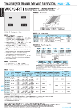
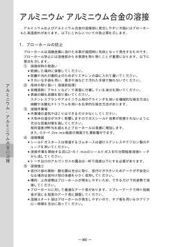
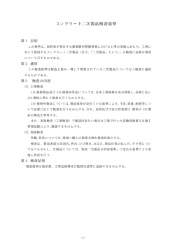
CPQ1S [3264]
電流検出用長辺電極チップ固定抵抗器 Current sensing wide terminal type thick film chip resistors
■構造及び材料 Structure,Materials
■特長 Features
*長辺電極の採用により、鉛フリーはんだにおける
フィレットクラック防止に役立ちます。
*面実装に対応しています。
*長辺電極の採用で、従来品と比較してより放熱性を向上
させる事が出来ました。この為、定格電力保証 2 W
を実現しています。
④
③
②
名称 Part name
*By wide terminal construction, Solder-joint reliability
was able to be raised sharply.
*Adoption of wide terminal construction raised heat dissipation
nature more conventionally as compared with elegance.
Rated electric power guarantee 2 W is realized.
①
材料 Materials
①基板
Substrate
高純度アルミナ
High purity alumina
②抵抗皮膜
Resistive film
銀パラジウム系厚膜
Ag palladium based thick film
③保護膜
Overcoat film
特殊ガラス
Special glass thick film
④内部電極
Inside termination
銀系厚膜
④中間電極
Intermediate termination
ニッケルメッキ+銅メッキ
Plated Ni film +Cu film
錫メッキ
Plated Sn film
Ag based thick film
④外部電極
Outside termination
*構造図は概略です。
■形名構成 Part No. Explanation (例) (ex.)
C
P
Q
品種
Product type
CPQ:
Current sensing
wide terminal type
thick film
chip resistors
1
S
T
T
R
8
0
3
0
J
定格電力
及びサイズ
Rated Power
and Size
梱包形態
Packaging form
端子構造
Terminal
structure
材料・収納方法
Material・storage
定格抵抗値
Nominal resistance value
抵抗値
許容差
Resistance
tolerance
1S:2W,
3264
T : 4mmピッチ
テープ
φ180 リール
T : 4mm pitch
taping
φ180 reel
T:2端子
T:2terminal
8:銀パラジウム系
厚膜抵抗体材料・
抵抗体形成面
上向きテープ収納
抵抗値を4桁の数字で表します。
例:R030=0.03Ω など
The resistance value is indicated
by 4-digit numbers.
J:±5%
F:±1%
*詳細は「梱包形頁をご覧下さい。
■外形寸法 Dimensions
L
W
c
保護膜色:黒 Overcoat film color : Black
T
CPQ1S
L
W
T
c
d
6.30±0.20
3.20±0.20
0.60±0.20
0.30±0.20
1.10±0.20
d
(単位 Unit : mm )
*寸法図はイメージ図です。詳細は各仕様書をご参照下さい。
-48-
CPQ1S [3264]
電流検出用長辺電極チップ固定抵抗器 Current sensing wide terminal type thick film chip resistors
■定格 Ratings
■負荷軽減曲線 Load-Derating Curve
*定格電力は、周囲温度70℃において連続負荷出来る
CPQ1S
最大電力です。周囲温度が70℃を超える場合は、図の
2W
定格電力
Rated power
負荷軽減曲線に従ってご使用下さい。
(70℃において、
放熱考慮の事)
定格抵抗値の許容差
Tolerance on rated resistance
J (±5%)
F (±1%)
カテゴリ温度範囲
Category temperature range
-55ºC~+155ºC
120
Rated load (%)
0.030Ω~0.20Ω
定 格電力 比︵
%︶
定格抵抗値の範囲
Range of rated resistance
負荷軽減曲線 Load-Derating Curve
70
100
80
60
40
20
155
0
-55
0
■部品温度データ
40
80
120
160
周囲温度(℃) Ambient temperature (℃)
*部品温度が155℃を超えない様に、ご注意下さい。
正方形銅箔 表面温度上昇
正方形銅箔 表面温度上昇
250
250
2W
1W
2W
1W
温度上昇(℃)
温度上昇(℃)
200
200
使用基板
・ガラス布基材エポキシ樹脂片面一層銅張積層板(FR-4)
・100×100×1.6Tmm、
・銅箔厚さ 0.035mm
3W
ランドサイズ
記号
寸法(mm)
150
150
100
100
a
1
b
4.4
c
6.3
b
a
c
e
5050
0 0
0
0
10
10
20
30
40
50
20
30
40
50
銅箔d=e寸法(mm□)
60
d
60
銅箔d=e寸法(mm□)
■代表的な性能及び試験方法 Specifications and test method
特性項目 Item
温度による抵抗値変化
Variation of resistance with temperature
特性 Specifications
抵抗値範囲
Resistance range
抵抗温度係数
T.C.R (10-6 /ºC)
0.030Ω~0.20Ω
0∼200
試験方法 Test method
JIS C5201-1 4.8
25ºC → 125ºC
過負荷
Overload
±( 2% + 0.002Ω)
JIS C5201-1 4.13
2.5×定格電圧、5秒
2.5×Rated voltage,for 5 seconds
耐プリント板曲げ性
Bend strength of the face plating
±( 1% + 0.002Ω)
JIS C5201-1 4.33
曲げ Bending distance : 3mm
はんだ耐熱性
Resistance to soldering heat
±( 1% + 0.002Ω)
JIS C5201-1 4.18
260 ±5ºC. 10秒間 (sec.)
はんだ付け性
Solderability
95%以上はんだカバー
Covered with more than 95%
JIS C5201-1 4.17
245 ±3ºC. 2秒間 (sec.)
温度急変
Rapid change of temperature
±( 1% + 0.002Ω)
JIS C5201-1 4.19
-55/20/125/20ºC. 5サイクル(times)
耐久性(耐湿負荷)
Loadlife in humidity
±( 3% + 0.002Ω)
60±2ºC. 90~95% R.H 1000h
70℃での耐久性
Endurance at 70ºC
±( 3% + 0.002Ω)
JIS C5201-1 4.25
70±2ºC. 1000h
JIS C5201 に準拠
-49-
Conforming to JIS C5201
© Copyright 2026 Paperzz