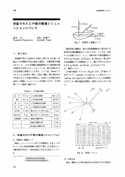
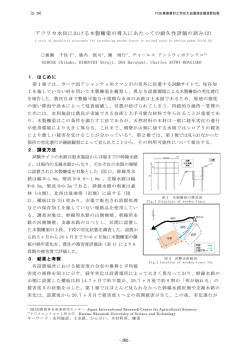
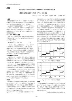
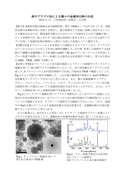
第 15回数値流体力学シンポジウム E14-1 重合格子法による船舶の波浪中3次元運動シミュレーション 3-dimensional motion simulation of a ship in waves using composite grid method 朴鍾千 , [email protected] 松尾博志, [email protected] 佐藤徹 , [email protected] 宮田秀明, [email protected] 東京大学 環境海洋工学専攻, 文京区本郷 7-3-1, Hiroshi Matsuo, J.C.Park, Toru Sato, and Hideaki Miyata Dept. of Environmental and Ocean Engineering, Univ. of Tokyo, 7-3-1 Hongo Bunkyo-ku Tokyo Japan In this study, a computational fluid dynamics simulation technique has been developed for unsteady motion of a ship advancing in waves. Composite grid system is employed in order to deal with large amplitude motions of ship and wave generation separately. The governing equations, Navier-Stokes (N-S) and continuity equations, are discretized by a finite volume method, in the framework of inner grid (O-H type) and outer grid(rectangular) systems. The present method is applied to simulate flow around ship heading on calm water and in forced motions. Wave maker is also tested. The results show that composite grid can cope with 6 D.O.F motion of ship and wave maker. 1.背景 (1)の外力項 K は、内部格子系と外部格子系でそれぞれ(2)、 (3)のようになる。 従来、船舶の製品としての性能、安全性は主として、試運 転状態での平水中推進性能、線形計算に基づく短期・長期予 測結果、及びに規則で定められた波浪外力というものさしで 評価されてきた。しかし、こうした設計手法では、船舶が就 航する波浪条件下での性能や安全性が設計段階で殆ど評価 されずに、特に、航路海象条件下での波浪中推進性能や、荒 天時、大波高中での船体の安全性が船舶設計に反映される事 が少なかった。このため、平水中性能を偏重した、波浪推進 性能の著しく劣る船舶や、大波高時の安全性の不十分な船舶 が建造され、航路就航時の速力不足や、船体構造損傷事故の 多発など、船舶の性能と安全性の両面で、製品品質の悪化を 招いている。 2.目的 このような背景から、本研究では、波浪中の船体運動、波 浪荷重を定量的に予測するために、船舶の大振幅運動を取り 扱う事が可能な CFD コードの開発を目的としている。具体 的には、波浪条件の入力が容易で、波の減衰や反射の問題が 少ない矩形格子系と、船体近傍での解析精度の良い物体適合 格子との重ね合わせを行う。このことにより適合格子の特徴 である物体周りの流体精度の高さを保ちつつ、Yaw 運動を含 めた船体の多自由度・大振幅運動シミュレーションを実現す る。この手法により、これまでは実船データに頼るしかなか った実海域での性能評価や、スラミング・ブローチング現象 のような多自由度大振幅運動の定量的理解が可能となる。 3.計算手法 本計算手法を概説する。流体計算では、非圧縮性流体 Navier-Stokes 方程式と連続の式を支配方程式としている。N・ S 式は(1)のようになり、 (1) 内部 (2) 外部 (3) 支配方程式を有限体積法により離散化し、MAC 法のアルゴ リズムで時間発展的に流場を解くことにより、各時間で支配 方程式を満足する非定常解を求めている。格子系は、内部格 子には船体表面に固定した O-H 型境界適合格子を、外部格 子には矩形格子系を用いている。本研究で用いた格子系を Fig 1 に示す。ベクトル変数はすべてデカルト系で定義され た成分を持ち、速度および圧力はスタッガード変数配置で定 義している。対流項の離散化には 3 次上流上差分を用い、そ の他の空間の離散化については 2 次精度中心差分を用いてい る。圧力解法には、SOR 法を用いている。時間の離散化には、 非定常計算における計算効率を考慮して 1 次精度のオイラー 陽解法を用いている。船体運動は、流場の計算から得られた 圧力、摩擦力を船体浸水表面上で積分して計算される外力を 用いて、剛体の運動方程式を各時間で解くことにより求める。 自由表面の取扱いに関しては、非線形性の強い自由表面変形 への対応を考慮して、密度関数法を用いている。Table.1 に本 論文で用いた計算手法を表形式にまとめた。 2 つの格子間の圧力・速度の受け渡しは、セル中心に速度 を内挿し、3 次元の線形補間を用いて行う。内部格子から外 部格子への補間は、内部格子をセルの面積ベクトルを用いて 矩形に変換し、線形補間係数を求め、内挿を行う。内部格子 から外部格子への線形補間係数の求め方の模式図を Fig.2 に しめす。 計算の流れは、まず、ある時間nステップ目での外部格子 系の流体計算を行い、つぎに内部格子系の外部境界に圧力・ 速度を内挿し、内部格子系の流体計算を行う。船体の運動は 内部格子系では船体固定座標系で行われるため、速度の受け 渡しに関しては、外部セルと内部セルの相対速度を加減した 速度を受け渡す。計算された内部格子系の値を、内部格子系 に含まれる、外部格子のセルに内挿し、次のタイムステップ に移る。 1 Copyright © 2001 by JSCFD Table.2 Series 60 model Block Coefficient Cb 0.6 Midship Section Coefficient Cm 0.9775 Length-breadth ratio Lpp/ B 7.50 Length between pp L [m] 1 Breadth B [m] 0.1333 Draught T [m] 0.0533 Wetted surface S [m2] 0.1699 Volume of displacement ∇ [m3] 4.252×10⁻³ Table.3 Condition of calculation for steadily heading ship Grid Points Inner 140 × 22 × 103 = 317420 Outer Fig 1 composite grid system Table.1 Simulation Methods 148 × 73 × 53 = 572612 Minimum grid space 0.001 Reynolds Number 1.0 × 10⁶ Froude number 0.316 Governing Eq.. N-S & Continuity Eqs. Dt 0.001 Algorism MAC Time of acceleration 3.0 Differencing Time Differencing Space Euler F ra m e 0 0 1 0 4 D e c 2 0 0 1 3rd order upstream(advection term), 2nd order centered (others) Variables Arrangement Staggered Mesh Turbulent Model Dynamic SGS model Free surface condition Marker Density Function (DFM) method 0 .0 0 0 4 0 .0 0 0 3 5 0 .0 0 0 3 0 .0 0 0 2 5 (Fluid)Body fixed coordinate system Inner grid F r ic t io n 0 .0 0 0 1 (Ship motion)Ground fixed coordinate Outer grid P re s s u re 0 .0 0 0 2 0 .0 0 0 1 5 5 E -0 5 (Fluid)Outer grid is fixed on the center of gravity 0 0 without any rotating motions、No Rotate 2 4 6 tim e 8 Fig.3 Time history of resistance (non-dimension) 0.02 ζ Mono grid Experiment Overset grid 0.01 0.01 0.00 -0.5 -0.4 -0.3 -0.2 -0.1 0 0.1 0.2 0.3 0.4 0.5 -0.01 N1= ( 1 - a1 ) × ( 1 - a2 ) N2= a1 ×( 1 - a2 ) N3= a1 ×a2 N4= ( 1 - a1 ))× ×a2 Fig2 -0.01 -0.02 Fig.4 Wave elevation on Series60 hull Interpolation Coefficient 4.定常航行テスト まず静水中での定常航行計算を行った。船体には Series60 船型を用いた。船体の主要目を Table.2 に、計算条件を Table.3 に示す。Fig.3 に抵抗の時系列を、Fig.4 に船側波形を示す。 Fig.4 の比較から、重合格子における計算が実験値と単一格 子による計算と定性的に一致している事が分かる。 Fig.5 Pressure contour at section=1.5 2 Copyright © 2001 by JSCFD 5.強制運動させた船体周りの計算 実際に強制運動シミュレーションを行う事により、本論文 で用いた数値計算法が、船体の運動の 6 自由度すべてに対し て応用が可能である事を示す。運動を強制して大振幅 Roll 運動、Roll, Yaw 運動、Surge, Sway 運動、Heave, Pitch 運動を 行った。 5.1 強制大振幅 Roll 運動シミュレーション 船体の回転運動(Roll、Pitch、Yaw)のうち、一般的に Roll 運動がもっとも大振幅運動の発生の可能性が大きい。船体の 大振幅の回転運動に対して本計算手法が応用できる事を確 認するために、Roll=20°の大振幅 Roll 強制運動計算を行っ た。タイムステップごとに内挿すべき点の検索を行い、補間 係数を求める。計算条件を Table.4 に、計算結果を Fig.6∼ Fig.11 に示す Fig.7 Grid distribution at section=1.5. Roll amplitude is 20 degree. Table.4 Condition of calculation for enforced roll motion simulation Inner 140 × 22 × 103 = 317420 Grid Points Outer 148 × 73 × 53 = 572612 Minimum grid space 0.001 Reynolds Number 1.0 × 10⁶ Froude number 0.316 0.001 3.0 Dt Time of acceleration Roll angle 20° 2.0 Period of Rolling Fig.7 Pressure contour at section=1.5. Fn=0.316 Frame 001 13 Dec 2001 non-dimension 0.0004 Total resistance 0.0003 Pressure 0.0002 Friction 0.0001 0 0 5 Fig.6 10 15 time Time history of resistance. Fn=0.316 Fig.10 Grid distribution on horizontal plane. Frame 001 11 Dec 2001 non-dimension Mx My Mz 0.0002 0.0001 0 -0.0001 5 Fig.7 time 10 15 Time history of moment. Fn=0.316 Fig.11 Instantaneous wave height contour map 3 Copyright © 2001 by JSCFD 5.2 強制 Roll、Yaw 運動シミュレーション 進行する船の方向は舵によって制御されている。舵は一般 的に船の重心よりも低い位置に取り付けられており、そのた めに舵が生み出す Yaw モーメントは同時に Roll モーメント も発生させている。また、波浪中では舵の Roll モーメントを 利用して Roll 角を制御することも可能である。この事から分 かるように Roll 運動と Yaw 運動は互いに連成していると考 えられる。 本論文で用いた計算手法が Roll 運動と Yaw 運動の連成問 題に応用できることを示すために、Roll 振幅 10°、Yaw 振幅 5°、周期2で強制運動させた船体の周りの流場計算を行っ た。計算条件を Table.5 に、Roll 角と Yaw 角の時系列を Fig.12 に、計算結果を Fig.13∼16 に示す。 Frame 001 11 Dec 2001 non-dimension 0.0005 Mx My Mz 0 -0.0005 5 Table.5 Grid Points Inner 140 × 22 × 103 = 317420 Outer 10 15 time Fig.14 Time history of moment. Fn=0.24 Roll amplitude is 10 degree. Yaw amplitude is 5.0 Condition of calculation for enforced roll and yaw motion 148 × 73 × 53 = 572612 Minimum grid space 0.001 Reynolds Number 1.0 × 10⁶ Froude number 0.24 Dt 0.001 Time of acceleration 3.0 Roll angle 10° Yaw angle 5.0° Period of Rotation 2.0 Frame 001 11 Dec 2001 10 Roll angle Yaw angle Fig15 Pressure contour at Section=1.0. Fn=0.24 Roll amplitude is 10 degree. Yaw amplitude is 5 degree 5 Degree 0 -5 0 5 time 10 Fig.12 Time history of Roll and Yaw angle. Fn=0.24 Frame 001 11 D ec 2001 non-dimension Fx(pressure) Fy(pressure) 0.0015 0.001 0.0005 0 -0.0005 Fig.16 Pressure contour at section=6.0. Fn=0.24 Roll amplitude is 10 degree. Yaw amplitude is 5 degree -0.001 -0.0015 0 5 10 time Fig.13 Time history of Fx Fy. Fn=0.24. Roll amplitude is 10 degree. Pitch amplitude is 5.0 4 Copyright © 2001 by JSCFD 5.3 強制 Surge、Sway 運動シミュレーション Frame 001 11 Dec 2001 non-dimension 海洋を航行する船舶が旋回を行う場合や停止をする場合、 必ず Surge 運動と Sway 運動を行う。ここでは、Surge と Sway の 2 つの方向に対して強制振動運動を行い船体周りの流場計 算を行った。Surge を船長の 1%の振幅、Sway を船長の 1.2% の振幅、周期2で強制振動運動させた船体の周りの流場計算 を行った。Table.6 に計算条件を、Fig.17 に X 方向の速度と Sway 方向の速度の時系列を、Fig.18∼20 に計算結果を示し た。 Table.6 0.0002 0 -0.0002 Condition of calculation for forced Surge and Sway simulation Grid Points Inner 5 148 × 73 × 53 = 572612 Minimum grid space 0.001 Reynolds Number 1.0 × 10⁶ Froude number 0.24 Dt 0.001 Time of acceleration 3.0 Amplitude of Surge 0.01 Amplitude of Sway 0.012 Period of oscillation 2.0 time 10 15 Fig.19 Time history of moment. Fn=0.24 Roll amplitude is 10 degree. Pitch amplitude is 5.0 140 × 22 × 103 = 317420 Outer Mx My Mz Frame 001 11 Dec2001 non-dimension Surge 0.2 Sway 0 -0.2 Fig.20 Pressure contour at section=1.5. -0.4 -0.6 -0.8 -1 0 5 time 10 15 Fig.17 Time history of enforced surge and sway velocity. Fn=0.24 Frame 001 11 Dec 2001 non-dimension Fx (pressure) 0.0006 Fy (pressure) 0.0004 0.0002 0 -0.0002 -0.0004 Fig.21 Instantaneous wave height contour map -0.0006 0 5 time 10 Fig.18 Time history of Fx and Fy. 15 (Pressure) 5 Copyright © 2001 by JSCFD 5.4 強制 Heave、Pitch 運動シミュレーション 波浪中の船体運動シミュレーションを行う準備として、造 波シミュレーションを行った。本論文では速度造波板を用い た。密度関数法を用いた自由表面を含む流体の造波機シミュ レーションは Park et al(11) (12)により、波崩れを伴う計算にお いても十分な精度があることが確かめられている。本研究で は重合格子を用いており、格子の境界で波のエネルギーが伝 播されているか、波の反射はないか確認した。計算条件を Table.に、計算結果を Fig.25,26 にしめす。 Fig の結果から、造波板で生成された規則波が内部格子に伝 播された事が確認された。今後船体無しの状態での造波テス トを行い、波が減衰することなく後方まで伝播されるかを確 認する予定である。 船舶が向かい波中を航行する場合、ある条件が重なるとス ラミングと呼ばれる、Heave 運動と Pitch 運動が同時に起こ る状況に陥ることがある。このスラミング状態では船首付近 の船底に衝撃圧がかかり、船体の損傷を引き起こす事もある。 ここでは、スラミング運動と密接に関連する Heave と Pitch の強制運動を行う。Table.7 に計算条件を、Fig.22∼24 に 計算結果を示した。 Table.7 Condition of calculation for heave and pitch motion Grid Points Inner Outer 140 × 22 × 103 = 317420 148 × 73 × 53 = 572612 Table.8 Condition of calculation for mechanical wave generating simulation Minimum grid space 0.001 Reynolds Number 1.0 × 10⁶ Froude number 0.24 Dt 0.001 Time of acceleration 3 Minimum grid space 0.001 Amplitude of Heave 0.006 Reynolds Number 1.0 × 10⁶ 1.5degree 1 Dt 0.001 Amplitude of Pitch Period of oscillation Grid Points Inner 140 × 22 × 103 = 317420 Outer Frame 001 14 Dec 2001 148 × 73 × 53 = 572612 Wave Length 1.1 Wave Height 0.022 0.0008 0.0006 0.0004 0.0002 0 -0.0002 -0.0004 -0.0006 0 5 time 10 A B Fig.22 Time history of resistance due to pressure. Frame 001 14 D ec 2001 0.002 0.0015 0.001 0.0005 0 -0.0005 Fig.25 Instantaneous wave height contour -0.001 -0.0015 F ra m e 0 0 1 0 9 N o v 2 0 0 1 -0.002 0 5 time 10 0 .0 1 Fig.23 Time history of My(pitching) moment. 0 .0 0 5 0 - 0 .0 0 5 - 0 .0 1 0 1 2 tim e 3 4 5 Fig.26 Time history of wave height at point A and B in Fig.25 Fig.24 Pressure contour on hull surface. 6.造波シミュレーション Pitch=-1.5 6 Copyright © 2001 by JSCFD 7.本研究の成果 本研究での成果を述べる。多重格子系を用いることにより、 船体の6自由度すべての運動を取り扱う事が出来ることを 示した。また、密度関数法を用いた自由表面を含む流体の造 波機シミュレーションを行い、本造波法が複合格子系にも適 用できることを示した。 8.今後の展望 今後、流体計算と船体運動方程式のカップリングを行うこ とにより、波浪中船体運動を解析することの出来る CFD コ ードの開発を行っていく。 参考文献 1) Aerodynamics of High Speed Trains Passing by Each other Kozo Fujii and Takanobu OGAWA 2) 船舶粘性流計算における、複合格子法の応用シミュレーション) 日本造船学会論文集 第 174 号 増子章 (第 2 報 船尾水平フィン付船体まわりの粘性流シミュレーショ ン)日本造船学会論文集 第 180 号 増子章 3) Chimera RANS Simulation of Nonlinear Waves Induced by a Heaving Cylinder PRAHORO YULIJANTO NURTJAHYO, TEXAS A&M University 4) B-Spline Method and Zonal Grids for Simulations of Complex Turbulent Flows Journal of Computational Physics 1999 G.Kravchenko, Parvis Moin and Karim Shariff 5) 3 次元運動を行う船体の CFD シミュレーション技術の開発と応 用 博士論文 1995 年 東大 秋元博路 6) CFD シミュレーションによるレーシングヨットの波浪中運動 性能評価法 修士論文 2000 年 東大 後藤公仁 7) CFD による船舶の波浪中運動シミュレーション法 修士論文 1999 年 東大 佐藤陽平 8) ブローチング現象発生機構に関する考察 日本造船学会論文集 1981 年 11 月 元良誠三、藤野正隆、小 柳雅志郎、石田茂資、島田和彦、牧岳彦 9) 小型船のブローチングに関する実験的研究 日本造船学会論文集 1981 年 11 月 不破健、吉野泰平、山本 徳太郎、菅井和夫 10) 多重格子法を用いた振動する円柱周りの流れの解析 第 14 回流体力学シンポジウム 小笠原和也 黒田成昭 電通 大 11) Jong-Chun Park, Ming Zhu, Hideaki Miyata : On the Accuracy of Numerical Wave Making Techniques, J. Soc. Naval Arch. Japan, Vol. 173, pp.35-44 (1993) 12) Jong-Chun Park, Hideaki Miyata, : Numerical Simulation of the 2D and 3D Breaking Waves by Finite-Difference Method., J. Soc. Naval Arch. Japan, Vol. 175, pp.11-24 (1994) 7 Copyright © 2001 by JSCFD
© Copyright 2026 Paperzz