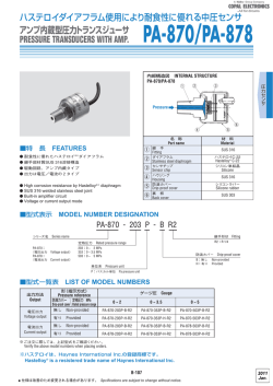
大型 LED 表示(2 色切替 , 3・1/2 表示)、小型軽量、高精度、高耐食性を実現
小型圧力ゲージ
COMPACT PRESSURE GAUGE
PG-75
内部構造図 INTERNAL STRUCTURE (9/16-18UNF)
マーキング
EMC指令適合
5
marking
Compatible with
EMC directive
4
6
2
7
3
1
■特 長 FEATURES
O小型・軽量・多機能の汎用圧力ゲージ
O圧力受圧部に SUS304/316 Lの溶接一体構造を採用
O 圧力表示機能が充実(3・1/2 桁、7 セグメント LED、2 色
LED 赤 / 緑切替、消灯モード)
O 電圧出力(1‒5V)/電流出力(4‒20mA)の 2 タイプのアナロ
グ出力
O 圧力レンジは、ゲージ圧(0 ∼正圧)、連成圧(負圧∼
正圧)があり、最大 3.5MPa まで対応
OIP65 対応、CE マーキング・UL 認証取得
O Compact, lightweight and multi-functional generalpurpose pressure gauge.
O I t i s a d o p t e d w e l d i n g i n t e g r a l s t r u c t u r e w i t h
SUS304/316L at pressure receiving section.
O A pressure display function is substantial. (3 1/2digit, 7
segment LED, 2-color LED red / green change, Nondisplay mode)
O Two types of analog output , one is voltage output
(1-5V),The other is current output(4-20mA).
OThe gage pressure is (0 ∼ positive pressure), compound
pressure range (negative pressure ∼ positive
pressure),to support maximum of 3.5 MPa.
O Comply with IP65, CE Marking and UL certification
obtained.
1
2
3
4
5
6
7
名 称
材 料
Part name
Material
SUS304
ダイアフラム
Diaphragm
SUS316L
継 手
Fitting
センサモジュール
Sensor module
センサホルダ
Sensor holder
アダプタ
Adapter
ケース
Housing
パネルシート
Panel sheet
ケーブル
Cable
( )
PBT
(UL-94-HB)
ポリエステル
Polyester
塩化ビニル
Vinyl chlorid resin (UL2844)
■型式表示 MODEL NUMBER DESIGNATION
P G - 7 5 - 1 0 2 R - N V R2 B
シリーズ名 Series name
定格圧力 Rated pressure
102G:0 ∼ 100kPa 102R:-100 ∼ 100kPa
103G:0 ∼ 1.0MPa 103R:-0.1 ∼ 1.0MPa
353G:0 ∼ 3.5MPa 353R:-0.1 ∼ 3.5MPa
SW 出力方式 Switch output interface
N:NPN オープンコレクタ N:NPN open collector
P:PNP オープンコレクタ P:PNP open collector
アナログ出力 Analog output
V:電圧出力(1‒5 V) V:Voltage output(1‒5 V)
A:電流出力(4‒20mA) A:Current output(4‒20mA)
圧力ポートの向き Pressure port
ブランク:垂直ポート Blank:Stem mount
B:背面ポート B:Back mount
継手形状(M5メネジ付き)
Fitting(With M5 female screw)
R1:R1/8
R2:R1/4
PG-75
COMPACT PRESSURE GAUGE
■型式一覧 LIST OF MODEL NUMBERS
圧力ポート
SW 出力
継手形状
Pressure
SW
Fitting
port
output
NPN
R1/8
PNP
垂直
Stem
NPN
R1/4
PNP
NPN
R1/8
PNP
背面
Back
NPN
R1/4
PNP
圧力レンジ(アナログ出力定格範囲) Pressure range (Rated range analog output )
アナログ出力
Analog
output
(0 ∼ 100kPa)
(-100 ∼ 100kPa)
(0 ∼ 1.0MPa)
(-0.1 ∼ 1.0MPa)
(0 ∼ 3.5MPa)
(-0.1 ∼ 3.5MPa)
1 ∼ 5V
4 ∼ 20mA
1 ∼ 5V
4 ∼ 20mA
1 ∼ 5V
4 ∼ 20mA
1 ∼ 5V
4 ∼ 20mA
1 ∼ 5V
4 ∼ 20mA
1 ∼ 5V
4 ∼ 20mA
1 ∼ 5V
4 ∼ 20mA
1 ∼ 5V
4 ∼ 20mA
⇒ PG-75-102G-NVR1
⇒ PG-75-102G-NAR1
⇒ PG-75-102G-PVR1
⇒ PG-75-102G-PAR1
⇒ PG-75-102G-NVR2
⇒ PG-75-102G-NAR2
⇒ PG-75-102G-PVR2
⇒ PG-75-102G-PAR2
⇒ PG-75-102G-NVR1B
⇒ PG-75-102G-NAR1B
⇒ PG-75-102G-PVR1B
⇒ PG-75-102G-PAR1B
⇒ PG-75-102G-NVR2B
⇒ PG-75-102G-NAR2B
⇒ PG-75-102G-PVR2B
⇒ PG-75-102G-PAR2B
⇒ PG-75-102R-NVR1
⇒ PG-75-102R-NAR1
⇒ PG-75-102R-PVR1
⇒ PG-75-102R-PAR1
PG-75-102R-NVR2
PG-75-102R-NAR2
⇒ PG-75-102R-PVR2
⇒ PG-75-102R-PAR2
⇒ PG-75-102R-NVR1B
⇒ PG-75-102R-NAR1B
⇒ PG-75-102R-PVR1B
⇒ PG-75-102R-PAR1B
⇒ PG-75-102R-NVR2B
⇒ PG-75-102R-NAR2B
⇒ PG-75-102R-PVR2B
⇒ PG-75-102R-PAR2B
⇒ PG-75-103G-NVR1
⇒ PG-75-103G-NAR1
⇒ PG-75-103G-PVR1
⇒ PG-75-103G-PAR1
⇒ PG-75-103G-NVR2
⇒ PG-75-103G-NAR2
⇒ PG-75-103G-PVR2
⇒ PG-75-103G-PAR2
⇒ PG-75-103G-NVR1B
⇒ PG-75-103G-NAR1B
⇒ PG-75-103G-PVR1B
⇒ PG-75-103G-PAR1B
⇒ PG-75-103G-NVR2B
⇒ PG-75-103G-NAR2B
⇒ PG-75-103G-PVR2B
⇒ PG-75-103G-PAR2B
⇒ PG-75-103R-NVR1
⇒ PG-75-103R-NAR1
⇒ PG-75-103R-PVR1
⇒ PG-75-103R-PAR1
PG-75-103R-NVR2
PG-75-103R-NAR2
⇒ PG-75-103R-PVR2
⇒ PG-75-103R-PAR2
⇒ PG-75-103R-NVR1B
⇒ PG-75-103R-NAR1B
⇒ PG-75-103R-PVR1B
⇒ PG-75-103R-PAR1B
⇒ PG-75-103R-NVR2B
⇒ PG-75-103R-NAR2B
⇒ PG-75-103R-PVR2B
⇒ PG-75-103R-PAR2B
⇒ PG-75-353G-NVR1
⇒ PG-75-353G-NAR1
⇒ PG-75-353G-PVR1
⇒ PG-75-353G-PAR1
⇒ PG-75-353G-NVR2
⇒ PG-75-353G-NAR2
⇒ PG-75-353G-PVR2
⇒ PG-75-353G-PAR2
⇒ PG-75-353G-NVR1B
⇒ PG-75-353G-NAR1B
⇒ PG-75-353G-PVR1B
⇒ PG-75-353G-PAR1B
⇒ PG-75-353G-NVR2B
⇒ PG-75-353G-NAR2B
⇒ PG-75-353G-PVR2B
⇒ PG-75-353G-PAR2B
⇒ PG-75-353R-NVR1
⇒ PG-75-353R-NAR1
⇒ PG-75-353R-PVR1
⇒ PG-75-353R-PAR1
PG-75-353R-NVR2
PG-75-353R-NAR2
⇒ PG-75-353R-PVR2
⇒ PG-75-353R-PAR2
⇒ PG-75-353R-NVR1B
⇒ PG-75-353R-NAR1B
⇒ PG-75-353R-PVR1B
⇒ PG-75-353R-PAR1B
⇒ PG-75-353R-NVR2B
⇒ PG-75-353R-NAR2B
⇒ PG-75-353R-PVR2B
⇒ PG-75-353R-PAR2B
⇒印の型式は受注生産です。
The products marked ⇒ are manufactured upon receipt of order basis.
■標準仕様 STANDARD SPECIFICATIONS
PG-75
型式
Model number
102G
形(指示方式)
Pressure reference
定格圧力
Rated pressure
Pr(L) ∼ Pr(H)
最大圧力
353R
Gauge
Gauge (Compound)
−100 ∼ 100kPa
−0.1 ∼ 1.0MPa
−0.1 ∼ 3.5MPa
Pmax
200kPa
2MPa
5MPa
200kPa
2MPa
5MPa
Pb
300kPa
3MPa
7MPa
300kPa
3MPa
7MPa
FS
100KPa
1MPa
3.5MPa
200kPa
1.1MPa
3.6MPa
適用媒体
Pressure Medium
一般仕様
103R
ゲージ圧(連成圧)
0 ∼ 3.5MPa
Break-down pressure
General specifications
102R
0 ∼ 1.0MPa
破壊圧力
Full-scale
353G
0 ∼ 100kPa
Maximum pressure
圧力スパン
103G
ゲージ圧
センサ封入液
Sealed liquid
SUS304 および SUS316L を腐蝕させない気体および液体
Corrosive gases/Liquids compatible with SUS304 or SUS316
シリコーンオイル Silicone oil
電源電圧
10.8 ∼ 30VDC(リップル含む) 10.8 ∼ 30VDC (Including ripple percentage)
消費電流
50mA 以下(アナログ出力電流は含まず) 50mA maximum (Not included current analog output)
Operating voltage Vopr
Consumption current
保護構造
Protection grade
動作温度
Operating temp.
動作湿度
Operating humidity
絶縁抵抗
Insulation resistance
耐電圧
Dielectric strength
取付形状
Fitting port types
受圧部材質
Fitting materials
質量
Net Weight
IP65(IEC 準拠)
IP65 of IEC
-10 ∼ 50℃(保存:-20 ∼ 70℃)
-10 ∼ 50℃ (Storage Temperature : -20 ∼ 70℃ )
35 ∼ 85% RH
DC500V にて 100MΩ 以上、リード線部一括と圧力ポート間
100MΩ minimum at DC500V between bundled leads and pressure port
AC500V1 分間、
リード線部一括と圧力ポート間(リーク電流 1mA 以下)
One minuts at AC500V between bundled leads and pressure port (1mA maximum leakage)
R1(R1/8)
、R2(R1/4)
ダイアフラム Diaphragm:SUS316L、継手 Fitting:SUS304
約 115±15g(ケーブル 2m 含む) Approx. 115±15g (incl. 2m cable)
PG-75
COMPACT PRESSURE GAUGE
■標準仕様 STANDARD SPECIFICATIONS
PG-75
型式
Model number
出力数
Number of outputs
スイッチ容量
Switching capacity
Switch output
スイッチ出力
残留電圧
Residual voltage
応差
Hysteresis
繰返し精度
Repeatability
スイッチ精度
Accuracy
応答性
Response
短絡保護
Protection
動作表示
State indication
電圧出力 Voltage output
Vo
出力精度
Accuracy
分解能
Resolution
Analog output
アナログ出力
出力抵抗
Output resistance
応答性
Response
電流出力 Current output
Io
出力精度
Accuracy
分解能
Resolution
負荷抵抗
Output resistance
応答性
圧力表示
Pressure display
Response
表示素子
Display element
表示周期
Display cycle
表示精度
Accuracy
102G
103G
353G
102R
103R
353R
2 点出力(NPN/PNP) Two outputs (NPN/PNP)
30VDC/100mA 以下
30VDC / 100mA maximum
1.2 V以下(NPN)/ 2.2 V以下(PNP)
、
負荷電流 100mA
1.2V maximum (NPN) / 2.2V maximum (PNP), Load current 100mA
0 ∼約 0.3Pr(H)
、
(可変) 0 ∼ Approx 0.3Pr(H),(Adjustable)
±0.3% FS/ 周囲温度 25℃ ±0.3 % FS / Reference temp. 25℃
±2% FS(総合精度 : 以下総合精度には調整誤差、Lin/Hys、温度特性誤差を含みます。
)
±2%FS (Integrated accuracy:Including errors of setting, linearity, hystresis and thermal error.)
約 5ms(デジタルフィルタ設定:"F0") Approx 5 ms (Digital filter settings :”F0”)
有り (SW 過負荷電流検出:約 150mA 以上)
Exists / Short circuit protection(Switch Overload current detection :Approx 150mA minimum)
SW モニタ LED(2 点)
、
各 SW が ON 時に点灯(圧力表示の反転色)
SW monitor LED(2 points) ,Lighted when the switch output is ON.(Pressure display inverted colors)
1 ∼ 5V/Pr(L)∼ Pr(H)
、
電圧出力スパン F.S.:4V
1 ∼ 5V / Pr(L) ∼ Pr(H) , F.S. : 4V
±2% F.S.(総合精度)/ 測定負荷抵抗(1MΩ 以上)
±2%F.S. (Integrated accuracy) /Measurement load resistance(1MΩmaximum)
Approx 2.7mV(Approx 0.068% F.S.)(11bitDAC)
1kΩ(内部インピーダンス)
Approx 1kΩ(Internal impedance)
約 2ms 以下 Approx 2ms maximum
4 ∼ 20mA/Pr(L)∼ Pr(H)、 電流出力スパン F.S.:16mA
4 ∼ 20mA / Pr(L) ∼ Pr(H), F.S. : 16mA
±2% F.S.(総合精度)/ 測定負荷抵抗(250Ω)
±2%F.S. (Integrated accuracy) /Measurement load resistance(250Ωmaximum)
Approx 0.011mA(Approx 0.068% F.S.)(11bitDAC)
Vopr ≦ 18VDC : 50 ∼ 300Ω, Vopr > 18VDC : 50 ∼ 500Ω
約 2ms 以下 Approx 2ms maximum
3・1/2 桁、7 セグメント LED、表示色(赤 / 緑)反転機能選択可(SW1 動作に連動)
3 1/2 digits, 7 segment LED (Red/Green) Reverse display selectable in tandem with SW1.
5 回 / 秒(移動平均表示)
5 times /sec(moving average)
±2% F.S.(総合精度)(Integrated accuracy)
■環境特性 ENVIRONMENTAL CHARACTERISTICS
試験項目 Test item
試験条件 Test conditions(At 25 ± 5 °C)
2
変動量 Permissible change
10 ∼ 500Hz、 振幅 1.5mm 以下 /98.1m/S 、3 方向、各 2 時間
10 ∼ 500Hz 1.5mm maximum / 98.1m/s2, three directions, two hours each 圧力表示、スイッチ動作圧力、アナログ出力
2
(Zero, Span)試験中最大:± 2%F.S.
490m/S 、3 方向、各 3 回
衝撃
Pressure indication, switch operating pressure and
490m/s2, three directions, three times each
Shock
analog output (zero and span) : ± 2%F.S.
圧力サイクル Pressure cycling
0 ∼定格圧力 0∼Rated pressure, 106 cycles
maximum during test
40 °C, 90∼95 %RH, 240 hrs.
耐湿性 Moisture resistance
振動
Vibration
PG-75
COMPACT PRESSURE GAUGE
■環境特性 ENVIRONMENTAL CHARACTERISTICS
試験項目 Test item
試験条件 Test conditions(At 25 ± 5 °C)
変動量 Permissible change
圧力表示、スイッチ動作圧力、アナログ出力 試験中最大:± 5 %F.S.
Pressure indication, switch operating pressure and
analog output : ± 5 %F.S. maximum during test
EMI : EN55011: 2009, A1: 2010 Group 1, class B
EMS : EN61326-1 : 2006 Table 2
EN61326-2-3 : 2006 Annex BB
EMC
■圧力表示倍率 MULTIPLIER FACTOR
動作条件設定の表示部 3 桁目のコードにより、表示倍率を設定します。
The multiplier factor is selectable by changing the value of third digit on the display during the operation setting.
圧力レンジ/定格圧力表示仕様 Pressure Range / Display specification rated pressure
102R
103G
103R
353G
コード/圧力表示倍率
Code/Multiplier Factor
102G
1:×1(kPa)
2:×0.0102
3:×10.2
4:×7.501
5:×0.01
6:×10
7:×0.145
8:×0.001(MPa)
9:×0.2953
0.0 ∼ 100.0
.000 ∼ 1.020
0 ∼ 1020
0 ∼ 750
.000 ∼ 1.000
0 ∼ 1000
0.0 ∼ 14.5
ー
0.0 ∼ 29.5
-100.0 ∼ 100.0
-1.020 ∼ 1.020
-1020 ∼ 1020
-750 ∼ 750
-1.000 ∼ 1.000
-1000 ∼ 1000
-14.5 ∼ 14.5
ー
-29.5 ∼ 29.5
0 ∼ 1000
0.00 ∼ 10.20
ー
ー
0.00 ∼ 10.00
ー
0.0 ∼ 145.0
.000 ∼ 1.000
0 ∼ 295
-100 ∼ 1000
-1.02 ∼ 10.20
ー
ー
-1.00 ∼ 10.00
ー
-14.5 ∼ 145.0
-.100 ∼ 1.000
-30 ∼ 295
ー
0.0 ∼ 35.7
ー
ー
0.0 ∼ 35.0
ー
0 ∼ 508
0.00 ∼ 3.50
0 ∼ 1033
353R
ー
-1.0 ∼ 35.7
ー
ー
-1.0 ∼ 35.0
ー
-15 ∼ 508
-0.10 ∼ 3.50
-30 ∼ 1033
・表の“ー”部は、分解能の関係で表示倍率が選択できないよう、表示いたしません。
・工場出荷時の設定は、圧力レンジ 1MPa 未満をコード“1”
(kPa)
、1MPa 以上をコード“8”
(MPa)とする。
・表示倍率の変更は圧力表示値に適用されます。また、表示倍率の変更によって、SW 圧力設定値及び応差設定は初期化されますのでご注意下さい。
・The settings indicated by "-" on the table above are not selectable because of resolution.
・Either "1"(for 102A, 102V, 102G, and 102R) or "8" (for 103G, 103R, 353G and 353R) are set prior to delivery.
・Changes of the multiplier factor apply to display values. Also, note the changes reset switch setting value and hysteresis.
■スイッチ出力モード SWITCH OUTPUT MODE
動作条件設定の表示部1桁目のコードにより、SW動作モードを設定します。
SW output is selectable by changing the value of first digit on the display.
<SW動作図 Switch Operation Mode>
<SW動作組み合わせ表 SW Operation Code>
出力
Output
Mode
Operation
SW1
セパレータ
Separate
HI
LO
ウインドコンパレータ
Window comparator
A
B
セパレータ
Separate
HI
LO
(HI動作 HI operation)
ウインドコンパレータ
Window comparator
A
B
1
2
3
4
5
6
7
8
圧力設定
(動作点)
Pressure setting
(Operating point)
ウインドコンパレータモード
Window comparator mode
セパレートモード
Separate mode
SW2
(A動作 A operation)
ON
OFF
ON
ON
OFF
P1/SW1
P1/SW1, P2/SW2
P2/SW2
-Pr
Pr
H
Pr
H
(L動作 L operation)
ON
P1/SW1
P2/SW2
-Pr
H
OFF
OFF
Pr
-Pr
設定1
Set 1
設定2
Set 2
OFF
P1/SW1, P2/SW2
H
P1≦P2 or P1≧P2
下限設定1
上限設定4
(Minimum)Set 1
(Maximum)Set 4
H
(B動作 B operation)
ON
下限設定1
上限設定3
(Minimum)Set 1
(Maximum)Set 3
P3/SW1, P4/SW2
-Pr
H
P3/SW1, P4/SW2
Pr
H
H
P1≦P3–2H and P2≦P4–2H
H:応差 Hysteresis、
P1=設定1 Set 1、P2=設定2 Set 2
P3=設定3 Set 3、P4=設定4 Set 4
・セパレートモードでは、SW1と設定1、SW2と設定2がそれぞれ対応します。
・ウインドコンパレータモードでは、SW1と設定1/3、SW2と設定2/4が対応します。
・応差Hは、SW1/2の動作モードに共通の設定です。
・SW動作モードを
(セパレート/ウインドコンパレータ)
間で変更した場合、
別途設定するSW圧力設定値はリセットされますので、
ご注意下さい。
䊶In the Separate mode, SW 1 corresponds to Setting 1 and SW2 corresponds to Setting 2.
䊶In the Window Comparator Mode, SW 1 corresponds to the Setting 1 䋨lower limit䋩 and Setting 3 䋨upper limit䋩. Also. SW2 corresonds to the setting 2
䋨lower limit䋩 and setting 4 䋨upper limit䋩.
䊶The Hysteresis 䋨H䋩 setting is common to SW 1 and SW 2 operations.
䊶When SW operation is changed between the Separate Mode and Window Comparator Mode, SW pressure settings that are set separately will be reset.
PG-75
COMPACT PRESSURE GAUGE
■外形寸法図(単位:mm)
EXTERNALS SPECIFICATION (unit:mm)
O背面ポートタイプ The horizontal installation type
R1/4継手:SUS304
33
R1/4Fitting
1H1
(73.5)
圧力単位:kPa/MPa
PANEL:PET
2-M4有効長さ5
13
16
□30
(16)
□30
7
(72)
定格圧力1MPa以上:MPa
SUS304,Width:14
Adoptor:PBT
Unit:kPa/MPa
面間幅:14
LOT. 1H1
(内径φ2.5/外径φ4)
アダプタ:PBT
kPa
MADE IN JAPAN
Air intake
37
LED-Cover:PBT
PG-75
R
LEDカバー:PBT
□31.4
PG-75-102R-NVR2B
LOT.
MADE IN JAPAN
大気開放口
(適用チューブ径)
PRESSURE RANGE:(-100∼100kPa)
BROWN:POWER SUPPY(10.8 ∼ 30VDC)CLASS2
BLACK:SWITCH1(NPN 30V100mA max.)
WHITE:SWITCH2(NPN 30V100mA max.)
GRAY:ANALOG OUT(1 ∼ 5V)
BLUE:COMMON
R
PG-75-103R-PAR2
PRESSURE RANGE:(-0.1∼1.0MPa)
BROWN:POWER SUPPLY(10.8 ∼ 30VDC)CLASS2
BLACK:SWITCH1(PNP 30V100mA max.)
WHITE:SWITCH2(PNP 30V100mA max.)
GRAY:ANALOG OUT(4∼20mA)
BLUE:COMMON
O垂直ポートタイプ
Vertical installation type
16±0.2
メタルインサート
7
Metal insert
Bs䠄Ni Plating䠅
13
R1/4継手:SUS304
R1/4Fitting
アダプタ:PBT
センサカバー:PBT
Adoptor:PBT
Cover:PBT
センサカバー:PBT
(32)
Cover:PBT
面間幅:14
5芯ケーブル
(φ4)
長さ2000±100
AWG26,
(UL STYLEZZ:2844)
圧力導入口
SUS304,Width:14
Pressure port
(15)
!"#$䠄%
&'()䠅
M5
(0.8)
めねじ部有効長さ6以上
䠄䠅 depth6
(シース、
絶縁体)
:軟質塩化ビニール
Wire color
Brown
Gray
Black
White
Blue
Shield
Connection
Power B
Analog output
Switch output 1
Switch output 2
Common
Fitting
■取付方法(オプション)
MEANS OF ATTACHMENT (Option)
O垂直ポートタイプ
Vertical installation type
O背面ポートタイプ The horizontal installation type
(5.7)
□40
4.5
PG-75
PG-75-102R-NVR2B LOT.1H1
R
PRESSURE RANGE:
(-100∼100kPa)
BROWN:POWERSUPPLY(10.8∼30VDC)CLASS2
BLACK:SWITCH1(NPN30V100mAmax.)
WHITE:SWITCH2(NPN30V100mAmax.)
GRAY:ANALOGOUT(1∼5V)
BLUE:COMMON
PG-75-103R-PAR2 LOT. 1H1
R
PRESSURE RANGE:(-0.1∼1.0MPa)
BROWN:POWER SUPPLY(10.8∼30VDC)CLASS2
BLACK:SWITCH1(PNP 30V100mA max.)
WHITE:SWITCH2(PNP 30V100mA max.)
GRAY:ANALOG OUT(4 ∼20mA)
BLUE:COMMON
(□42.6)
24.7
kPa
パネルホルダーカバー
パネルホルダー
Panel holder cover
Panel holder
※ PG-30、PG-35、PG-75 シリーズ共用のアクセ
サリー(別売)をご用意しております。
(P.173)
Accessories (sold separately) are available for
common use with PG-30, PG-35, PG-75 series. (P.173)
■内部電気回路 INTERNAL ELECTRICAL SCHEMATICS
O NV/NA:NPN
OPV/PA:PNP
Pressure Display LED
圧力
Pressure
Output resistance
センサ
Sensor
主回路
Main circuit
NPN/SW Output circuits
Pressure Display LED
Power supply
Aout
SW1
SW2
負荷
Load
負荷
Load
圧力
Pressure
SW1
センサ
Sensor
SW2
主回路
Main circuit
PNP/SW Output circuits
Output resistance
COM.
FG:金属継手部
Frame Ground
Power supply
Aout
COM.
FG:金属継手部
Frame Ground
負荷
Load
負荷
Load
© Copyright 2026 Paperzz