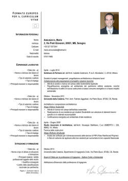
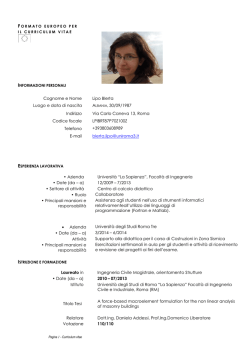
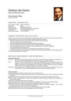
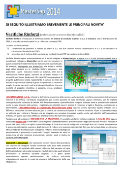
QUALITY CONTROL AND MONITORING OF FRP APPLICATIONS
TO MASONRY STRUCTURES
Renato S. Olivito and Francesca A. Zuccarello
Department of Structural Engineering, University of Calabria
Via Pietro Bucci, cubo 39B, 87036 Rende (CS), Italy
[email protected] - [email protected]
ABSTRACT
The use of composite materials in strengthening and restoring interventions on existing structures is continuously increasing.
During the last decades, many researchers have developed new strategies, technical solutions and analyses. In particular, the
Italian CNR DT 200/2004 [1] technical recommendations for the design and construction of strengthening techniques with FRP
systems have been published to provide an aid to designers interested in the field of composite materials and to avoid their
incorrect application. The Guidelines deal with different types of FRP applications both to masonry and reinforced concrete
structures and take into account several tests for the quality control and monitoring of FRP installation. In the present work, the
results of semi-destructive and non-destructive techniques conducted for the quality control and monitoring of FRP
applications to masonry, according to CNR DT 200/2004 Guidelines, are reported. Pull-off tests and shear tearing tests have
been performed on real brick and natural stone masonry buildings for the assessment of the quality of FRP application. Finally,
non-destructive tests have been carried out to characterize the uniformity of FRP installation by means of thermographic tests.
Different types of FRP fabrics have been adopted. The tests allowed the validation and assessment of procedures, methods
and theoretical relationships suggested in the Guidelines.
Introduction
During the last few decades, fiber-reinforced composite materials (FRP) have been utilized in many Civil Engineering
applications. Their use in strengthening and restoring interventions on existing structures is greatly increasing due to their
considerable strength/weight ratio and excellent corrosion resistance, as a consequence of the fact that conservation and
restoration of the built heritage of past generations is becoming a key issue.
For this reason, huge scientific researches have been made by national and international engineering community for the
safeguard of historical buildings. These have lead to several research projects; in particular, CNR DT 200/2004 technical
recommendations [1] for the design and construction of strengthening techniques with FRP systems have been published in
Italy to provide an aid to designers interested in the field of composite materials and to avoid their incorrect application.
The Guidelines deal with different types of FRP applications to masonry and reinforced concrete structures and take into
account quality control and monitoring phases that should follow a strengthening intervention. In fact, several aspects affect
the effectiveness of FRP systems: above all, surface preparation and FRP installation are the most important ones. Moreover,
once FRP strengthening has been carried out, monitoring by non-destructive or semi-destructive tests should be performed to
assure the intervention quality and effectiveness [2 – 3 – 4].
In the present work, semi-destructive and non-destructive techniques have been conducted for the quality control and
monitoring of FRP applications to masonry structures, according to CNR DT 200/2004 Guidelines. Different types of FRP
fabrics have been adopted: carbon fiber and glass fiber fabrics. In particular, both pull-off tests and shear tearing tests have
been performed on real brick and natural stone masonry buildings for the assessment of the restored surface properties and
the quality of bond between FRP and masonry substrate, respectively. Moreover, non-destructive tests have been carried out
to characterize the uniformity of FRP application by means of thermographic tests. These tests have been conducted in the
laboratory on brick masonry macro-elements and on real masonry structures, with the aim of detecting defects on the
strengthening interventions used for the above mentioned semi-destructive tests.
The semi-destructive test results were useful for the experimental validation and assessment of procedures, methods and
theoretical relationships suggested in [1]. Finally, interesting information have been obtained regarding the different behavior
of the various FRP materials used.
Experimental program
The experimental program reported in the present work was divided into the following phases:
semi-destructive tests, consisting in both pull-off tests and shear tearing tests conducted on different types of FRP
fabrics applied on in situ masonry buildings;
non-destructive tests, consisting in thermographic tests carried on both masonry macro-elements at University of
Calabria and on in situ masonry structures.
Both semi-destructive and non-destructive tests have been conducted according to the Italian Guidelines reported in [1].
Semi-destructive tests: experimental procedure and results
FRP application has to be checked to ensure the correct installation and the durability of the intervention; the recent Italian
technical recommendations [1] take into account the important phases of quality control and monitoring of composite material
application on masonry and reinforced concrete structures. Such operations can be carried out by means of semi-destructive
tests and should be performed on small FRP elements to ensure the effectiveness of the proposed strengthening solution.
The tests described in the present work have been carried out to assess and verify the procedures and the theoretical
relationships proposed in the recent Guidelines [1]. In fact, it is well known that, even if the use of composite materials is
increasing, the need of experimentation is an important task and should always be taken into account together with a
theoretical study.
Semi-destructive tests described in the present work consist in pull-off tests and shear tearing tests. These tests have been
conducted on 8 real stone and brick masonry buildings placed in the south of Italy, nearby University of Calabria. According to
[1], after the substrate preparation by means of removal and reconstruction of any deteriorated masonry zone, cleaning of the
surface and removal of possible vegetation plant or similar, and the execution of tests on the homogeneity of the structure to
be strengthened, FRP fabric can be applied on a regular surface. As stated in [1], when semi-destructive tests are planned for
the quality control of a composite material application, together with the fabric used for the strengthening intervention, it is
suggested to provide additional strengthening areas, called “witnesses”, in properly selected portions of the structure. These
should be realized at the same time of the intervention, using the same technique and materials. Following the above
mentioned suggestions, two different types of strips have been applied onto masonry wall surfaces, with dimensions of 20x30
cm and 5x30 cm used for pull-off tests and shear tearing tests respectively.
Pull-off tests, used to assess the properties of the strengthened substrate, have been carried out attaching a thick circular 75
mm diameter steel plate to the FRP and isolating it from the surrounding FRP with a core drill, taking particular care in avoiding
heating of the FRP system while a 1-2 mm incision of masonry substrate is achieved. The test consists in pulling off the steel
plate by means of an ad hoc device, as shown in Figure 1. The test gives the ultimate pull-off strength value expressed in kN.
According to [1], FRP application may be considered acceptable if at least 80% of the tests return a pull-off stress not less than
10% of masonry support compressive strength, provided that failure occurs in the support itself, as shown in Figure 1-c. The
main results obtained from pull-off tests are reported in Table 1.
It is worth noting that, for an accurate comparison with semi-destructive test results, it would have been interesting the direct
evaluation of masonry walls compressive strength. Due to the impossibility of carrying out direct tests on the support (such as
flat jack tests), the typical value of compressive strength suggested in many National Codes [5 – 6] for stone and brick
masonry structures was taken into account. With this aim, a value of 2 MPa and 12 MPa was considered for stone and brick
masonry support, respectively. From Table 1 it can be noticed that in all cases the strength limit value suggested in [1] has
been reached. Moreover, failure in the substrate always has occurred (Figure 1-c), for each type of FRP material applied.
Shear tearing tests are instead used to assess the quality of bond between FRP and masonry substrate. These tests can be
conducted only when it is possible to pull a portion of the FRP system in its plane located close to an edge detached from the
masonry substrate. The tests have been carried out using the same ad hoc device used for pull-off tests, as shown in Figure 2.
In particular, metallic elements have been set up onto the masonry wall and through the FRP strip, with the aim of connecting
the entire test device. Then, the FRP element has been tightened until collapse. At the end of the test, the failure tearing force
could be obtained, expressed in kN.
In this case, FRP application may be considered acceptable if at least 80% of the tests return a peak tearing force not less
than 5% of masonry support compressive strength [1]. Table 2 shows the shear tearing test main results, which have been
positive in all cases. Also during this test, the compressive strength value of the support, indicated in the Tables 1 and 2, was
taken into account according to the Italian Codes [5 – 6].
a)
b)
c)
d)
Figure 1. Pull-off test on a stone masonry building: a) FRP and substrate incision; b) experimental equipment assembling;
c) test conduction; d) test result.
a)
b)
Figure 2. Shear tearing test on a brick masonry building: a) experimental equipment; b) test result.
Support
Compressive
Strength
(MPa)
12
2
2
2
12
2
2
2
Table 1. Pull-off test results
Table 2. Shear tearing test results
Pull-off stress (MPa)
Shear tearing stress (MPa)
Glass Fibers
Test
n.1
1,36
0,34
0,41
0,73
1,84
1,86
2,20
1,70
Test
n.2
0,30
1,11
0,91
1,66
0,73
1,14
Test
n.3
0,86
1,41
1,07
-
Carbon Fibers
Test
n.1
0,77
0,91
1,48
2,09
1,23
1,50
1,07
0,66
Test
n.2
1,27
1,23
1,52
0,00
0,64
1,27
1,36
Test
n.3
1,30
1,14
0,80
-
Support
Compressive
Strength
(MPa)
12
2
2
2
12
2
2
2
Glass Fibers
Carbon Fibers
Test
n.1
0,18
0,24
0,23
0,25
0,34
0,16
0,21
0,23
Test
n.1
0,67
0,65
0,89
0,78
0,83
0,74
0,64
1,03
Non-destructive tests: experimental procedure and results
It is well known that the success of FRP materials in performing their functions strongly depends on how well they are bonded
to the substrate. For this reason there is need to detect and characterize defects after their application. Italian Guidelines
described in [1] suggest many non destructive techniques both for the evaluation of interface and bonding defects and for
monitoring long term behavior of the strengthening intervention. Among these, thermographic tests have been adopted in the
present work. In particular, these kind of non destructive tests, usually carried out to characterize the uniformity of FRP
3
application, have been conducted on both brick masonry macro-elements of dimensions 52 x 52 x 12 cm at University of
Calabria and on the same real masonry structures used for the above mentioned semi-destructive tests.
Infra Red thermography is based on the principle that heat transfer in any material is affected by the presence of subsurface
flaws or any other change in material thermal properties. The changes in heat flow cause localized energy differences on the
surface of the test object, which can be measured using an infrared detector (thermocameras). Through data processing, the
measured infrared radiation levels are transformed into their corresponding temperature distributions and recorded in the form
of thermograms. Irregularities in the thermogram indicate the presence of anomalies in the test object. The relationship
between the surface temperature and emitted radiation is based on the Stefan-Boltzmann principle, described by equation (1):
E = σ ε T4
(1)
2
where E is the radiant emissivity (W/m ), T is the absolute temperature (K), ε is the unitless emissivity of the investigated
-8
2 4
object and σ is the Stefan-Boltzmann constant equal to 5,67×10 W/m K .
In the present experimentation the active thermography technique has been adopted, in which thermal energy is applied
externally and uniformly onto the test object and transient heat transfer phenomena occur. In this way, the surface temperature
of the object is monitored as a function of time by measuring the emitted radiation. The external heating has been reached by
means of two 500 W halogen lamps, symmetrically placed in front of the specimen surface with respect to the thermocamera’s
visual field. Enough care has to be taken to avoid the reaching of glass transition temperature for the epoxy resin, equal to
about 50°C. By means of the thermocamera, it has been possible to detect the IR radiation emitted indicated in Celsius
degrees.
A control specimen has been adopted to evaluate the potential of detection and to estimate the environmental conditions (such
as the environmental temperature reflection) and material emissivity that affect thermographic tests [7 – 8 – 9]. In particular, on
a brick masonry specimen, before the application of carbon fiber strips, controlled flaw have been created by placing different
materials, with different dimensions, at the interface between the substrate and CFRP fabrics, such as to simulate the
presence of voids or irregular surface planarity. Moreover, material emissivity has been measured through the known
emissivity of a reference material.
The first IR thermographic tests have been conducted in the laboratory on brick masonry macro-elements, which have been
reinforced by carbon fiber strips placed in different directions onto the specimen surfaces. Figure 3 shows one of the most
indicative thermograms collected during the experimentation referred to a specimen reinforced with a diagonal 10 cm wide
CFRP strip. In particular, Figure 3-a shows the monochromatic thermogram from which a mortar joint is clearly visible due to
the non plane substrate surface. In Figure 3-b the defect detection is better shown in a colored thermogram: each color
represents a different temperature level. The other hot areas of the thermogram, with the same color of the ones
corresponding to the mortar joint, are associated to reflection effect caused by the environment; this assumption was
confirmed by the fact that varying the thermocamera’s angle of incidence the areas in object disappeared.
a)
b)
Figure 3. Brick masonry macro-element reinforced by carbon fiber strips subjected to thermographic test:
a) Monochromatic thermogram; b) Defect detection.
Figure 4. Infrared thermographic test on in situ stone masonry building: fibers position on the wall surface,
temperature bar chart and temperature trend along the fibers.
The second part of non destructive tests has been carried out on the same in situ masonry structures taken into account
during semi-destructive investigations. In particular, the Infra Red thermographic tests have been conducted on the FRP strips
used for pull-off and shear tearing tests. Also in this case, the active technique has been adopted.
As an example, Figure 4-a shows the position of a glass fiber strip and a carbon fiber strip applied onto a stone masonry
building. From the thermogram no flaws or defects have been observed, meaning a perfect bond between FRPs and the
substrate, as shown in the temperature trend of Figure 4-b where no peaks are present.
It is worth noting that, in any case, thermographic tests allowed to point out the perfect application of the composite strips used
for the subsequent semi-destructive tests.
Concluding remarks
Quality control and monitoring FRP strengthening interventions are fundamental tasks for the durability of the application itself
and nowadays these are topical problems due to the recent use of new materials. The experimentation described in the
present work takes into account these subjects. In particular, according to the recent Italian Guidelines regarding FRP use in
Civil applications [1], non destructive tests, such as Infra Red thermography, have been used to investigate the intervention
homogeneity and the uniformity of the composite application. From these kind of tests, the possible presence of air bubbles or
void can be observed. In the present case, no defects could be noticed on in situ building tests, meaning the perfect bond
between FRP and the masonry substrate. The main difficulty consisted in the investigation on glass fiber strips: due to the light
color of this kind of composite material, a clear vision of them was not always possible.
Non destructive tests, consisting in pull-off tests and shear tearing tests, are used to assess the quality of the strengthened
substrate and the quality of bond between FRP and masonry. These tests have pointed out the different behavior between
different FRP materials. In particular, Figure 5 clearly shows the tests results: it can be noticed that glass fibers have lower
shear strength compared with carbon ones. This phenomenon is also visible if the failure mode is studied. As shown in Figure
6, while carbon fiber strips delaminated from the substrate in almost all cases, glass fiber ones broke off without delamination.
Moreover, the difficulty in the execution of shear tearing tests is worth noting, due to the high weight of the metallic elements
used for the test, and the limited dimensions of the strip to be pulled, due to the device dimensions. These two factors affect
the test results. However, in any case, the limit stress value suggested in [1] has been respected.
1,20
2,50
GFRP
1,00
2,00
CFRP
1,50
1,00
0,50
0,00
Shear peak stress (MPa)
Pull-off peak stress (MPa)
GFRP
CFRP
0,80
0,60
0,40
0,20
0,00
1
2
3 4
5
6
7
8
9 10 11 12 13 14 15 16 17 18
Num ber of tests
1
2
3
4
5
6
7
8
Num ber of tests
a)
b)
Figure 5. Different behavior of FRP materials: a) Pull-off test results; b) Shear tearing test results.
With the aim of better analyzing the experimental results, a comparison between experimental shear tearing test results and
the theoretical relationships introduced in [1] is being developed. At present, the following equation (2) has been used for the
determination of the maximum force allowed to the FRP reinforcement:
Fmax = b f ⋅ 2 ⋅ E f ⋅ t f ⋅ Γ F
(2)
where bf, tf and Ef represent FRP thickness, width and Young modulus respectively, while ΓF is the specific fracture energy
which depends on masonry support compressive strength (fmk,) and tensile strength (fmtm) and on geometrical parameters (kG
and kb), according to equation (3).
Γ F = kG ⋅ kb ⋅
(3)
f mk ⋅ f mtm
The first results have been obtained dividing Fmax by the FRP glued area; in this way, the maximum bond strength has been
2
2
found equal to 0,56 N/mm and 0,13 N/mm for carbon and glass fiber reinforcement respectively, which can be clearly
compared with most of the experimental results reported in Table 2.
However, it is suggested that further experimentation is needed to better understand the interaction between strengthening
intervention and the substrate and for a deeper analysis and comparison with the theoretical studies reported in [1].
a)
b)
Figure 6. Shear tearing failure mode: a) Carbon fiber strip; b) Glass fiber strip.
Acknowledgments
This work was supported by RELUIS Project (2005-2008), Research Line n.8 “Innovative materials for vulnerability reduction
of existing structures” coordinated by Prof. L. Ascione and Prof. G. Manfredi, in the framework of Task 8.10 titled “Quality
control and monitoring” coordinated by Prof. R. S. Olivito.
References
1.
2.
3.
4.
5.
6.
7.
8.
9.
Various Authors, CNR DT 200/2004, “Guide for the Design and Construction of Externally Bonded FRP Systems for
Strengthening Existing Structures”, Italian National Research Council, Rome (2004).
Ascione, F., Feo, L., Olivito, R.S. and Poggi, C., “La qualificazione dell’esecuzione degli interventi di rinforzo strutturale
con FRP a margine delle recenti ”Istruzioni per la progettazione, l’esecuzione ed il controllo di interventi di consolidamento
statico mediante l’utilizzo di compositi FRP””, Proceedings of National Italian Conference “Ambiente e Processi
Tecnologici – La certificazione di Qualità dei materiali e dei prodotti da costruzione” (in Italian), Naples (2005).
Bastianini, F., Olivito, R.S., Pascale, G. and Prota, A., “Controllo di qualità e monitoraggio dei rinforzi in FRP”, L’Edilizia,
139, 66-71 (2005).
Olivito, R.S. and Zuccarello, F.A., “Indagine sperimentale per il controllo dell’applicazione di materiali FRP a strutture
murarie mediante prove semi-distruttive e non distruttive”, Proceedings of National Italian Conference on Materials and
Structures Experimentation (in Italian), Venice (2006).
Decreto Ministeriale 20/11/1987. Norme tecniche per la progettazione, esecuzione e collaudo degli edifici in muratura e
per il loro consolidamento. G.U. suppl. 285 del 5/12/87 (in Italian).
Norme Tecniche per le Costruzioni D.M. 14/09/05 Gazzetta Ufficiale n. 222 del 23/11/05 (Italian Version).
UNI 9252:1988. Thermal insulation. Qualitative detection of thermal irregularities in building envelopes. Infrared method
(Italian Version).
Pla-Rucki, G.F. and Eberhard, M.O., “Imaging of reinforced concrete: state-of-the-art review”, ASCE Journal of
Infrastructure systems, 1 (2), 134-141 (1995).
Starnes; M.A., Carino; N.J. and Kausel, E.A., “Preliminary Thermography Studies for Quality Control of Concrete
Structures Strengthened with Fiber-Reinforced Polymer Composites”, ASCE Journal of Materials in Civil Engineering, 15
(3), 266-273 (2003).
© Copyright 2026 Paperzz