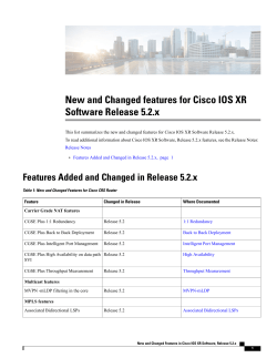
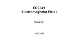
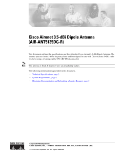
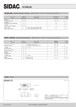
Installing Cisco ONS 15216-MD-ID-50
Optical Interleaver and Deinterleaver
Pluggable
Introduction
This document explains how to install and operate the Cisco ONS 15216
50 GHz/100 GHz optical interleaver and deinterleaver module inside the patch
panel.
The interleaver and deinterleaver module provides signal interleaving and
deinterleaving in 50-GHz channel spacing DWDM systems.
The 15216-MD-ID-50=: 50 GHz/100 GHz interleaver and deinterleaver module
operates inside the 15216-MD-40-ODD or 15216-MD-40-EVEN patch panel.
Note
The interleaver and deinterleaver module can be inserted inside an odd or an even
patch panel. This document considers the installation of the interleaver and
deinterleaver module inside an odd patch panel. For installing the patch panel,
refer to the “Installing the Cisco ONS 15216-MD-40-ODD and
15216-MD-40-EVEN Mux/Demux Patch Panels” guide.
Americas Headquarters:
Cisco Systems, Inc., 170 West Tasman Drive, San Jose, CA 95134-1706 USA
Introduction
Safety Information
Before you install, operate, or service the Cisco ONS 15216 50 GHz/100 GHz
optical interleaver and deinterleaver module (also referred as the ONS
15216-MD-ID-50), you must read the Regulatory Compliance and Safety
Information for Cisco Optical Transport Products document for important safety
information and warning translations.
The ONS 15216-MD-ID-50 is compliant with GR 1089, UL60950 /CSA 22.2 No.
60950-00, and IEC 60950 standards.
Laser Radiation Emission Restrictions
The interleaver and deinterleaver module is Class 1M Laser safety compliant,
which indicates that the product should never be used or installed in an optical
network with emissions higher than Class IM.
Warning
Class 1M laser radiation when open. Do not view directly with optical
instruments. Statement 281
Laser Safety During Operation
Warning
Invisible laser radiation may be emitted from disconnected fibers or
connectors. Do not stare into beams or view directly with optical instruments.
Statement 1051
Electrical Safety
The ONS 15216-MD-ID-50 is optically and electrically passive and require no
electrical connections. No electrostatic discharge (ESD) or other electrical safety
considerations apply.
Installing Cisco ONS 15216-MD-ID-50 Optical Interleaver and Deinterleaver Pluggable
2
78-19072-01
Product Description
Product Description
The ONS 15216-MD-ID-50 is a C-band 50 GHz/100 GHz module that operates
inside the patch panel. The ONS 15216-MD-ID-50 module interfaces between the
15216-MD-40-ODD and 15216-MD-40-EVEN patch panels, and 80 channels of
wavelengths. The advantages of installing the C-band 50 GHz/100 GHz module
is as follows:
•
Extends existing network capacity
•
Provides low cost future proofing of network capacity
•
Allows for non-traffic affecting capacity upgrade, when the patch panel is
equipped with the ONS 15216-MD-ID-50 module at first installation.
Features
The ONS 15216-MD-ID-50 is a modular component that provides signal
interleaving and de-interleaving in 50 GHz channel spacing DWDM systems. It is
optically and electrically passive and requires no temperature control. It uses
fused fiber coupler technologies and a birefringent crystal technology platform.
The operating features of the ONS 15216-MD-ID-50 module include:
•
Low dispersion
•
Low insertion loss
•
High channel isolation
•
Wide clear bandwidth
•
Full C-band coverage
•
Interleave and Deinterleave 80-channels
•
Athermal design
Installing Cisco ONS 15216-MD-ID-50 Optical Interleaver and Deinterleaver Pluggable
78-19072-01
3
Functional Description
Functional Description
The ONS 15216-MD-ID-50 module increases the network capacity by combining
two optical data streams into a single, more densely spaced stream. This module
can be used in mux mode to combine two 100 GHz optical signal streams into one
50 GHz stream, or in demux mode to separate the 50 GHz stream into two
100 GHz streams.
The ONS 15216-MD-ID-50 is a bidirectional module in which the mux and
demux functions are implemented in two different sections to enable signals
flowing in opposite directions to be managed separately. This functionality is
illustrated in Figure 1.
Figure 1
Functional Description of the Interleaver and Deinterleaver
Module
DEMUX
Section
ODD-TX
ODD+EVEN RX
EVEN-TX
50/100 GHz Deinterleaver
MUX
Section
ODD-RX
ODD+EVEN TX
50/100 GHz Interleaver
275724
EVEN-RX
The interleaver in the mux section combines the even and odd channel signals at
100 GHz spacing (EVEN-RX and ODD-RX ports, respectively) into the 50 GHz
channel spacing signal.
Installing Cisco ONS 15216-MD-ID-50 Optical Interleaver and Deinterleaver Pluggable
4
78-19072-01
Functional Description
The deinterleaver in the demux section separates the 50 GHz channel spacing
signal into even and odd channel signals of 100 GHz spacing (EVEN-TX and
ODD-TX ports, respectively).
The interleaver and deinterleaver module is plugged inside the patch panel and is
interconnected with another patch panel of a different grid.
Optical Interconnections
The optical interconnections between the odd patch panel, interleaver and
deinterleaver module and the even patch panel is shown in Figure 2.
Patch Panel Interconnection with Interleaver and Deinterleaver
Module
ODD+EVEN TX
ODD-RX
COM-TX
ODD+EVEN RX
50Ghz/100Ghz
Interleaver
50Ghz/100Ghz
Deinterleaver
EVEN-RX
ODD-TX
EVEN-TX
COM-RX
40-MUX-ODD
40-DMUX-ODD
Ch1-TX
Ch2-TX
Ch3-TX
Ch40-TX
Ch1-RX
Ch2-RX
Ch3-RX
Ch40-RX
152 16-MD-40-ODD
COM-TX
40-MUX-EVEN
COM-RX
40-DMUX-EVEN
275698
Figure 2
152 16-MD-40-EVEN
The port connections between the odd patch panel, interleaver and deinterleaver
module, and the even patch panel are established as follows:
•
COM-TX port of the odd patch panel and ODD-RX port of the interleaver and
deinterleaver module.
Installing Cisco ONS 15216-MD-ID-50 Optical Interleaver and Deinterleaver Pluggable
78-19072-01
5
Functional Description
•
COM-RX port of the odd patch panel and ODD-TX port of the interleaver and
deinterleaver module.
•
COM-TX port of the even patch panel and EVEN-RX port of the interleaver
and deinterleaver module.
•
COM-RX port of the even patch panel and EVEN-TX port of the interleaver
and deinterleaver module.
Channel Wavelength Allocation
Table 1 describes the channel plan for the interleaver and deinterleaver module.
Table 1
C-Band Channel Wavelength Plan
Channel Wavelength Odd_C Band
Channel Wavelength Even_C Band
Channel
Label
Frequency Wavelength
(THz)
(nm)
Channel
Label
Frequency Wavelength
(THz)
(nm)
1
195.9
1530.33
2
195.85
1530.72
3
195.8
1531.12
4
195.75
1531.51
5
195.7
1531.90
6
195.65
1532.29
7
195.6
1532.68
8
195.55
1533.07
9
195.5
1533.47
10
195.45
1533.86
11
195.4
1534.25
12
195.35
1534.64
13
195.3
1535.04
14
195.25
1535.43
15
195.2
1535.82
16
195.15
1536.22
17
195.1
1536.61
18
195.05
1537.00
19
195
1537.40
20
194.95
1537.79
21
194.9
1538.19
22
194.85
1538.58
23
194.8
1538.98
24
194.75
1539.37
25
194.7
1539.77
26
194.65
1540.16
27
194.6
1540.56
28
194.55
1540.95
29
194.5
1541.35
30
194.45
1541.75
31
194.4
1542.14
32
194.35
1542.54
Installing Cisco ONS 15216-MD-ID-50 Optical Interleaver and Deinterleaver Pluggable
6
78-19072-01
Functional Description
Channel Wavelength Odd_C Band
Channel Wavelength Even_C Band
Channel
Label
Frequency Wavelength
(THz)
(nm)
Channel
Label
Frequency Wavelength
(THz)
(nm)
33
194.3
1542.94
34
194.25
1543.33
35
194.2
1543.73
36
194.15
1544.13
37
194.1
1544.53
38
194.05
1544.92
39
194
1545.32
40
193.95
1545.72
41
193.9
1546.12
42
193.85
1546.52
43
193.8
1546.92
44
193.75
1547.32
45
193.7
1547.72
46
193.65
1548.11
47
193.6
1548.51
48
193.55
1548.91
49
193.5
1549.32
50
193.45
1549.72
51
193.4
1550.12
52
193.35
1550.52
53
193.3
1550.92
54
193.25
1551.32
55
193.2
1551.72
56
193.15
1552.12
57
193.1
1552.52
58
193.05
1552.93
59
193
1553.33
60
192.95
1553.73
61
192.9
1554.13
62
192.85
1554.54
63
192.8
1554.94
64
192.75
1555.34
65
192.7
1555.75
66
192.65
1556.15
67
192.6
1556.55
68
192.55
1556.96
69
192.5
1557.36
70
192.45
1557.77
71
192.4
1558.17
72
192.35
1558.58
73
192.3
1558.98
74
192.25
1559.39
75
192.2
1559.79
76
192.15
1560.20
77
192.1
1560.61
78
192.05
1561.01
79
192
1561.42
80
191.95
1561.83
Installing Cisco ONS 15216-MD-ID-50 Optical Interleaver and Deinterleaver Pluggable
78-19072-01
7
Installation
Installation
This section explains how to:
•
Unpack and Verify the Equipment
•
Install the Interleaver and Deinterleaver Module
•
Install and Route Fiber-Optic Cables
Unpack and Verify the Equipment
This procedure describes the steps for unpacking and verifying the equipment.
Step 1
Unpack and inspect the module. The package should include these components:
•
ONS 15216-MD-ID-50 module
•
Production test report form showing the manufacturer's part number and
serial number, Cisco part number, date, and device description
•
Packing slip
Step 2
Compare the equipment received with the packing slip and the equipment list that
customer service provided. If there are any discrepancies, notify the Customer
Service Center.
Step 3
Check for external damage. Visually check all components and immediately
report any shipping damage to your customer service representative. Have this
information ready:
•
Invoice number of shipper (see packing slip)
•
Model and serial number of the damaged unit
•
Description of damage
•
Effect of damage on the installation
•
Packing slip
Installing Cisco ONS 15216-MD-ID-50 Optical Interleaver and Deinterleaver Pluggable
8
78-19072-01
Installation
Install the Interleaver and Deinterleaver Module
The ONS 15216-MD-ID-50 module is plugged inside the patch panel. The patch
panel is a new ONS 15216 FlexLayer unit that can be installed either above or
below the DWDM generating equipment according to the local site practice. For
installing the patch panel, refer to the “Installing Cisco ONS 15216 40-Channel
Mux/Demux Patch Panel” guide.
The ONS 15216-MD-ID-50 module is passive and requires no power cabling or
connections. All connectors are on the front panel and are equipped with LC/UPC
bulkhead adapters and with a USB Type A receptacle connector for inventory
purpose. Fiber-optic cables equipped with the corresponding (LC/UPC) connector
type are used. The module ports are labelled on the faceplate. The port
assignments of the module is provided in Figure 9. Refer to Table 2 for port label
description.
Caution
Use only the fastening hardware provided with the interleaver and deinterleaver
module to prevent loosening, deterioration, and electromechanical corrosion of
the hardware and joined material.
Installing Cisco ONS 15216-MD-ID-50 Optical Interleaver and Deinterleaver Pluggable
78-19072-01
9
Installation
This procedure describes the steps to install the interleaver and deinterleaver
module.
Step 1
To open the front panel of the patch panel:
a.
Drag the two front panel lockout mechanisms downward, as shown in
Figure 3.
b.
Open the front panel to its maximum position.
Figure 3
Cisco ONS 15216 Odd Patch Panel
275711
Front Panel
Lockout
Mechanism
Front Panel
Front Panel
Lockout
Mechanism
Installing Cisco ONS 15216-MD-ID-50 Optical Interleaver and Deinterleaver Pluggable
10
78-19072-01
Installation
Step 2
To extract the internal drawer of the patch panel:
a.
Push the extraction latch with one hand. (See Figure 4.)
b.
Pull the drawer holding the finger tab with the other hand. (See Figure 4.)
Cisco ONS 15216 Odd Patch Panel—Opened Front Panel and
Drawer in the Recessed Position
275700
Figure 4
Drawer
Finger
Tab
Extraction
Latch
Installing Cisco ONS 15216-MD-ID-50 Optical Interleaver and Deinterleaver Pluggable
78-19072-01
11
Installation
c.
Extract the drawer from the patch panel until the insertion latch is engaged.
(See Figure 5.)
Figure 5
Cisco ONS 15216 Odd Patch Panel—Opened Front Panel and
Drawer in the Extracted Position)
275706
Left
Fiber Bend
Radius
Controller
Drawer
Finger
Tab
Insertion Latch
I/D Blank
Cover
Cable
Retention Clip
Right
Fiber Bend
Radius
Controller
Installing Cisco ONS 15216-MD-ID-50 Optical Interleaver and Deinterleaver Pluggable
12
78-19072-01
Installation
Step 3
Note
Step 4
Unscrew the captive screws to remove the I/D blank cover. (See Figure 6.)
During an in-field upgrade, all the fibers installed previously must be routed
toward the left fiber bend radius controller. To plug in the interleaver and
deinterleaver module, the space in front of the I/D blank cover must be free of
fibers and cables.
Plug the interleaver and deinterleaver module, as shown in Figure 6.
Figure 6
Cisco ONS 15216 Odd Patch Panel—Plugging the Interleaver
and Deinterleaver Module
I/D Blank
Cover
275707
Captive
Screw
Captive
Screw
Inventory
USB Type A
Receptacle
Connector
Interleaver/Deinterleaver
Module
Installing Cisco ONS 15216-MD-ID-50 Optical Interleaver and Deinterleaver Pluggable
78-19072-01
13
Installation
Step 5
Tighten the screws of the interleaver and deinterleaver module. (See Figure 7.)
Figure 7
Cisco ONS 15216 Odd Patch Panel Plugged with Interleaver and
Deinterleaver Module
Cable
Retention Clip
275708
Left
Fiber Bend
Radius
Controller
LC-LC Adapter
Left USB
Cable Clamp
Foam
Pad
Step 6
Inventory USB
Type A Receptacle
Connector
I/D Box
Spool
Right USB
Cable Clamp
Right Fiber Bend
Radius Controller
To connect the fibers as appropriate:
a.
Remove the LC adapter cap from the LC-LC adapter. (See Figure 7.)
b.
Open the cable retention clip of the left or right fiber bend radius controller.
(See Figure 7.)
c.
Route the cables through the left or right fiber bend radius controller. Refer
to Table 2 for port label description and Figure 9 for channel identification
port information. For fibering instructions, see the “Fiber-Optic Connector
Cleaning and Maintenance” section on page 18 and the “Install and Route
Fiber-Optic Cables” section on page 21.
The LC-LC patch cords are used to connect the interleaver and deinterleaver
module to the patch panels. The extra fiber length of the two LC-LC patch
cords used to connect the patch panel with its plugged I/D box is placed on
the I/D box spool, as shown in Figure 8. The I/D box spool can be removed
from the interleaver and deinterleaver module and the extra fiber length of the
two LC-LC patch cords can be routed outside the patch panel.
Installing Cisco ONS 15216-MD-ID-50 Optical Interleaver and Deinterleaver Pluggable
14
78-19072-01
Installation
For interconnections between the interleaver and deinterleaver module, odd
patch panel and the even patch panel, see the “Optical Interconnections”
section on page 5.
Step 7
To connect the inventory USB Type A plug connector to the inventory USB Type
A receptacle connector:
a.
Route the inventory USB cable through the left or right fiber bend radius
controller. (See Figure 8.)
b.
Connect the USB Type A plug connector to the USB Type A receptacle
connector. (See Figure 8.)
Figure 8
Cisco ONS 15216 Odd Patch Panel Plugged with Interleaver and
Deinterleaver Module
Cable
Retention Clip
275705
Left
Fiber Bend
Radius
Controller
Drawer
Finger
Tab
Insertion Latch
Left USB
Cable Clamp
Inventory USB
Type A Receptacle
Connector
Foam Pad
I/D Box Spool
Note
Right USB
Cable Clamp
In Figure 8, the right fiber radius controller is made invisible.
Installing Cisco ONS 15216-MD-ID-50 Optical Interleaver and Deinterleaver Pluggable
78-19072-01
15
Installation
Step 8
Caution
Step 9
To secure the USB plug cable:
a.
Unscrew the captive screw of the left or right USB cable clamp. (See
Figure 8.)
b.
Rotate to open the USB cable clamp. (See Figure 8.)
c.
Place the cable on the foam pad. (See Figure 8.)
d.
Rotate the clamp to its original position. (See Figure 8.)
e.
Tighten the captive screw to lock the USB cable. (See Figure 8.)
The ONS 15216-MD-ID-50 module features LC/UPC bulkhead adapters. It uses
fiber-optic cables equipped with the corresponding (LC/UPC) connector type
with no fiber pigtail leading out. Using any other type of connector damages the
connector and/or adapter.
To place the patch panel in the closed working configuration:
a.
Close the cable retention clips to secure the cables after all the cables are
connected and routed within the fiber bend radius controllers. (See Figure 8.)
b.
Push the insertion latch with one hand. (See Figure 8.)
c.
Push the drawer holding the finger tab with the other hand. (See Figure 8.)
d.
Push the drawer inside the patch panel until the extraction latch is engaged.
(See Figure 4.)
e.
Close the front panel until the front panel lockout mechanisms are engaged.
(See Figure 3.)
Installing Cisco ONS 15216-MD-ID-50 Optical Interleaver and Deinterleaver Pluggable
16
78-19072-01
Installation
Port Label Description
Table 2 lists the connection ports, description, and the type of connectors used for
each port. All ports are on the front panel, which is equipped with optical LC
adapters and one USB Type A receptacle connector.
Table 2
Port Label Descriptions
Port Label
Description
Type of Connector
ODD+EVEN-RX
Common input
LC-UPC II
ODD-TX
Odd channels output
LC-UPC II
EVEN-TX
Even channels output
LC-UPC II
ODD+EVEN-TX
Common output
LC-UPC II
ODD-RX
Odd channels input
LC-UPC II
EVEN-RX
Even channels input
LC-UPC II
INV
USB inventory port
USB Type A receptacle
connector
Channel Identification Label
The channel identification label is placed on the interleaver and deinterleaver
module faceplate:
Figure 9 shows the product identification and channel identification label of the
interleaver and deinterleaver module.
Installing Cisco ONS 15216-MD-ID-50 Optical Interleaver and Deinterleaver Pluggable
78-19072-01
17
Installation
TX
RX
TX
275723
ODD
INV
ODD+EVEN
RX
15216-MD-ID-50=
TX
EVEN
Interleaver and Deinterleaver Module—Product and Channel ID
Label
RX
Figure 9
Fiber-Optic Connector Cleaning and Maintenance
Connector cleaning is required to maintain the performance of fiber-optic circuits.
It is important that both the LC/UPC connector at the end of the fiber-optic cable
and the mating bulkhead adapter on the front panel of the patch panel are clean
before the connection is made.
Warning
Invisible laser radiation may be emitted from disconnected fibers or
connectors. Do not stare into beams or view directly with optical instruments.
Statement 1051
The following warning applies to disposal of chemicals and other materials used
to clean connectors and adapters:
Warning
Ultimate disposal of this product should be handled according to all national
laws and regulations. Statement 1040
Installing Cisco ONS 15216-MD-ID-50 Optical Interleaver and Deinterleaver Pluggable
18
78-19072-01
Installation
Note
Before installing the fiber-optic cable, always perform the cleaning procedure for
cable connectors described in the following section. Whenever possible, inspect
each connector before connecting it to the mating bulkhead adapter on the front
panel.
Note
The LC bulkhead adapters on the ONS 15216-ID-50 front panel are less likely to
get dirty if they are capped when not in use. Because the procedure for a thorough
cleaning of these adapters is complicated and involves opening the patch panel,
Cisco recommends that you use a commercially available cleaning kit and closely
follow the instructions included with the kit. Only a simple, routine cleaning
procedure for these adapters that can be easily performed by the customer is
described here.
Customer Supplied Cleaning Materials
The Type A fiber optic connector cleaners (for example, CLETOP reel) are
recommended to clean the cable connectors, but are not supplied with the patch
panel.
When cleaning a paired cable connector (bulkhead mating adapter), always clean
the mating adapter first.
If properly maintained (only used with clean, defect-free fiber connectors and
capped when not in use), the mating adapter would not require cleaning. However,
if you suspect the adapter is dirty, clean it by using the CLETOP stick swab.
Note
For multi-fiber cable assemblies, use specific cleaning tools or materials designed
for the assembly type.
Clean the Bulkhead Mating Adapters
Step 1
Read the manufacturer (cleaning cartridge) instructions to insert the cartridge
cleaning tip into the mating adapter.
Installing Cisco ONS 15216-MD-ID-50 Optical Interleaver and Deinterleaver Pluggable
78-19072-01
19
Installation
Step 2
Slide the lever on the cartridge to swipe the mating surface.
Note
Always keep unused adapter ports and fiber connectors capped with a
clean dust cap.
Clean Fiber-Optic Cable Connectors
The tools required to clean fiber connectors are:
•
Inspection microscope
•
Type A Fiber Optic Connector Cleaner (CLETOP reel)
•
Optical swab
•
Optical receiver cleaning stick
Step 1
Using an inspection microscope, inspect each fiber connector for dirt, cracks, or
scratches.
Step 2
Replace any damaged fiber connectors.
Note
Caution
Step 3
Replace all dust caps whenever the equipment is unused for 30 minutes or more.
Do not reuse optical swabs. Keep unused swabs off of work surfaces.
Clean the fiber connectors with CLETOP reel:
a.
Remove the dust cap from the fiber connector.
b.
Press the lever down to open the shutter door. Each time you press the lever,
you expose a clean wiping surface.
c.
Insert the connector into the CLETOP cleaning cassette slot, rotate one
quarter turn, and gently swipe downwards.
d.
Use an inspection microscope to inspect each fiber connector for dirt, cracks,
or scratches. If the connector is not clean, repeat Steps a to b.
Installing Cisco ONS 15216-MD-ID-50 Optical Interleaver and Deinterleaver Pluggable
20
78-19072-01
Install and Route Fiber-Optic Cables
e.
Note
Insert the fiber connector into the applicable adapter or attach a dust cap to
the fiber connector.
If you must replace a dust cap on a connector, first verify that the dust cap is clean.
To clean the dust cap, wipe the outside of the cap using a dry, lint-free wipe and
the inside of the dust cap using a CLETOP stick swab (14100400).
Install and Route Fiber-Optic Cables
Warning
Invisible laser radiation may be emitted from disconnected fibers or
connectors. Do not stare into beams or view directly with optical instruments.
Statement 1051
Caution
When connecting an optical fiber patch cord between the patch panel and the
optical card ports in the ONS 15454, use the electrostatic discharge wristband
supplied with the ONS 15454. Plug the wristband into the ESD jack on the lower
right front side of the ONS 15454.
Note
Always clean all fiber connectors thoroughly before making the connection with
the mating adapter. Very small particles can permanently damage the end of the
mating fiber inside the patch panel, which makes regular cleaning imperative. For
cleaning instructions see “Fiber-Optic Connector Cleaning and Maintenance”
section on page 18.
Note
The interleaver and deinterleaver module features LC/UPC bulkhead adapters.
Always use fiber-optic cables equipped with the corresponding (LC/UPC)
connector type. Using any other type of connector results in damage to the
connector and/or adapter.
Installing Cisco ONS 15216-MD-ID-50 Optical Interleaver and Deinterleaver Pluggable
78-19072-01
21
Uninstalling the Module
Step 1
Place the LC/UPC cable connector in front of the corresponding bulkhead adapter
on the front panel of the patch panel.
Step 2
Align the keyed ridge of the cable connector with the slot in the receiving adapter.
Step 3
Gently push the cable connector into the adapter until you hear a click, which
indicates that the latching system is engaged.
Step 4
Route the fiber cables through the left or right fiber bend radius controller and
secure them into place closing the cable retention clip. (See Figure 8.)
Uninstalling the Module
This procedure describes the steps for removing the interleaver and deinterleaver
module from the patch panel.
Step 1
Open the front panel of the patch panel.
To open the front panel, follow the instructions in Step 1 of the “Install the
Interleaver and Deinterleaver Module” section on page 9. (See Figure 3.)
Step 2
Extract the internal drawer of the patch panel.
To extract the internal drawer, follow the instructions in Step 2 of the “Install the
Interleaver and Deinterleaver Module” section on page 9. (See Figure 4 and
Figure 5.)
Step 3
Open the cable retention clip of the fiber bend radius controller on the appropriate
side of the patch panel. (See Figure 8.)
Step 4
Gently disconnect the fiber-optic connectors from the LC-LC adapters of the
interleaver and deinterleaver module. (See Figure 8.)
Step 5
Disconnect the inventory USB cable releasing it from the USB cable clamp and
from the USB receptacle connector of the interleaver and deinterleaver module.
Clear the front of the interleaver and deinterleaver module from any cable or fiber.
(See Figure 8.)
Step 6
Unscrew the captive screws of the interleaver and deinterleaver module.
(See Figure 6.)
Step 7
Remove the interleaver and deinterleaver module from the patch panel.
(See Figure 6.)
Installing Cisco ONS 15216-MD-ID-50 Optical Interleaver and Deinterleaver Pluggable
22
78-19072-01
Interleaver and Deinterleaver Specifications
Step 8
Close the empty space on the patch panel with the I/D Blank Cover.
(See Figure 5.)
Step 9
Close the cable retention clip.
Step 10
Insert the patch panel drawer. (See Figure 4.)
Step 11
Close the front panel of the patch panel. (See Figure 3.)
Interleaver and Deinterleaver Specifications
This section contains environmental, optical, and mechanical specifications for
the interleaver and deinterleaver module.
Environmental Specifications
Table 3 provides the environmental specifications for the interleaver and
deinterleaver module.
Table 3
Environmental Performance Specifications
Environmental Condition
MIN
Short Term (96 hours/year) -5
Temperature Range (STR) 23
MAX
Units
55
Celsius
131
Fahrenheit
Continuous Operative
Temperature Range (OTR)
5
40
Celsius
41
104
Fahrenheit
Power Handling for the
Optical Port
500
Power Handling for the
USB Port
400
mW
600
mW
Optical Specifications
Table 4 provides the optical specifications for the interleaver and deinterleaver
module.
Installing Cisco ONS 15216-MD-ID-50 Optical Interleaver and Deinterleaver Pluggable
78-19072-01
23
Interleaver and Deinterleaver Specifications
Table 4
Optical Specifications
Parameter
Condition
Min
Max
Units
50 GHz /100 GHz Channel Grids
ITU Channel Center
Frequencies /Wavelength
•
ODD+EVEN
ports
191.95
195.85
THz
1530.72
1561.83
nm
ITU Channel Spacing
•
within short
term
temperature
range
50
•
ODD ports
192.0
195.9
THz
•
within short
term
temperature
range
1530.33
1561.42
nm
100
•
EVEN ports
191.95
195.85
THz
•
within short
term
temperature
range
1530.72
1561.83
nm
Number of Channels
ITU Channel Center
Frequencies /Wavelength
ITU Channel Spacing
Number of Channels
ITU Channel Center
Frequencies /Wavelength
ITU Channel Spacing
Number of Channels
GHz
80
GHz
40
100
GHz
40
Deinterleaver Module
Operating Bandwidth
-0.50 dB Clear
Bandwidth
•
-1.0 dB Clear Bandwidth
•
any state of
polarization
(SOP) and
within
operative
temperature
range
-10
+10
GHz
- 10
+10
GHz
- 12
- 12
GHz
around ITU
center
wavelength
Installing Cisco ONS 15216-MD-ID-50 Optical Interleaver and Deinterleaver Pluggable
24
78-19072-01
Interleaver and Deinterleaver Specifications
Parameter
-0.50 dB Clear
Bandwidth
Condition
•
-1.0 dB Clear Bandwidth
Adjacent Channel
Isolation1-DEMUX
any state of
polarization
(SOP) and
within short
term
temperature
range
•
around ITU
center
wavelength
•
any state of
polarization
(SOP) and
within short
term
temperature
range
•
within
operating
bandwidth
Min
Max
Units
+8
-8
GHz
- 10
+10
GHz
25
dB
Interleaver Module
Operating Bandwidth
-0.50 dB Clear
Bandwidth
•
-1.0 dB Clear Bandwidth
•
any state of
polarization
(SOP) and
within
operative
temperature
range
- 10
+10
GHz
- 10
+10
GHz
- 12
+ 12
GHz
around ITU
center
wavelength
Installing Cisco ONS 15216-MD-ID-50 Optical Interleaver and Deinterleaver Pluggable
78-19072-01
25
Interleaver and Deinterleaver Specifications
Parameter
-0.50 dB Clear
Bandwidth
Condition
•
-1.0 dB Clear Bandwidth
Adjacent Channel
Isolation2-MUX
any state of
polarization
(SOP) and
within short
term
temperature
range
•
around ITU
center
wavelength
•
any state of
polarization
(SOP) and
within short
term
temperature
range
•
within
operating
bandwidth
Min
Max
Units
-8
+8
GHz
- 10
+ 10
GHz
25
dB
Common Optical Specifications for Interleaver and Deinterleaver Module
Installing Cisco ONS 15216-MD-ID-50 Optical Interleaver and Deinterleaver Pluggable
26
78-19072-01
Interleaver and Deinterleaver Specifications
Parameter
Insertion Loss
Condition
3
•
Insertion Loss
Uniformity4
Channels Band Ripple
Group Delay Ripple
(GDR)
5
Chromatic Dispersion6
•
Optical Return Loss
Polarization Dependent
Loss (PDL)7
•
Min
Max
Units
any state of
polarization
(SOP) and
within
operative
temperature
range
1.5
2.5
dB
0.5
dB
0.3
dB
2.5
ps
within
operating
bandwidth
-20.0
+20.0
ps/nm
40.0
including
connectors
Polarization Mode
Dispersion (PMD)8
Directivity ODD <-->
EVEN ports
dB
0.4
dB
0.3
ps
40.0
dB
1. Adjacent Channel Isolation is defined as the difference between the maximum IL in the 50 GHz
transmitted channel Bandwidth (ITU ± 80 pm) and the minimum IL measured over the
Operating Wavelength Bandwidth (± 80 pm, centered on each ITU wavelength of the channel)
of both adjacent 100 GHz channels.
2. Adjacent Channel Isolation is defined as the difference between the maximum IL in the 50 GHz
transmitted channel Bandwidth (ITU ± 80 pm) and the minimum IL measured over the
Operating Wavelength Bandwidth of both adjacent 100 GHz channels.
3. The Insertion Loss values are measured as the maximum IL inside the Operating Wavelength
Bandwidth.
4. Insertion Loss Uniformity is defined as the difference between the maximum insertion losses
over any two operating wavelength bandwidths.
5. The difference between the maximum and minimum group delay in the Operating Wavelength
Bandwidth of each channel evaluated at all SOP.
6. Chromatic Dispersion is defined as the maximum of derivative of the Group Delay versus the
wavelength curve in the 50 GHz transmitted channel bandwidth (Operating Wavelength
Bandwidth)
7. PDL (Polarization Dependent Loss) is defined as the difference between the maximum and
minimum IL in the 100 GHz transmitted channel Bandwidth (Operating Wavelength
Bandwidth) evaluated at all SOP, measured at a given wavelength.
8. PMD (Polarization Mode Dispersion) is defined as the maximum of the DGD versus the
wavelength curve in the 50 GHz transmitted channel bandwidth (Operating Wavelength
Bandwidth).
Installing Cisco ONS 15216-MD-ID-50 Optical Interleaver and Deinterleaver Pluggable
78-19072-01
27
Related Documentation
Mechanical Specifications
The mechanical dimensions of the package are indicated in Table 5.
Table 5
Mechanical Specifications
Parameter
Condition
Specification
Connector Type
All optical
ports
LC/UPC II
USB
inventory
port
USB Type A receptacle connector
All optical
ports
LC
Adapter Type
Interleaver and Deinterleaver Module
Dimensions
9.911-inches (251.7 mm) long,
2.645-inches (67.2 mm) wide, and
2.452-inches (62.2 mm) high.
Considering the captive screw
brackets, the interleaver and
deinterleaver module width is
3.54- inches (89.9 mm).
Related Documentation
Use this document in conjunction with the following referenced publications:
•
Cisco ONS 15454 DWDM Reference Manual
•
Cisco ONS 15454 DWDM Procedure Guide
•
Cisco ONS 15454 DWDM Troubleshooting Guide
Visit the End-of-Life and End-of-Sale Notices page for EOL and EOS
announcements.
Installing Cisco ONS 15216-MD-ID-50 Optical Interleaver and Deinterleaver Pluggable
28
78-19072-01
Obtaining Documentation and Submitting a Service Request
Obtaining Documentation and Submitting a Service
Request
For information on obtaining documentation, submitting a service request, and
gathering additional information, see the monthly What’s New in Cisco Product
Documentation, which also lists all new and revised Cisco technical
documentation, at:
http://www.cisco.com/en/US/docs/general/whatsnew/whatsnew.html
Subscribe to the What’s New in Cisco Product Documentation as a Really Simple
Syndication (RSS) feed and set content to be delivered directly to your desktop using
a reader application. The RSS feeds are a free service and Cisco currently supports
RSS Version 2.0.
Cisco and the Cisco logo are trademarks or registered trademarks of Cisco and/or its affiliates in the U.S. and other
countries. To view a list of Cisco trademarks, go to this URL: www.cisco.com/go/trademarks. Third-party
trademarks mentioned are the property of their respective owners. The use of the word partner does not imply a
partnership relationship between Cisco and any other company. (1110R)
Any Internet Protocol (IP) addresses and phone numbers used in this document are not intended to be actual addresses
and phone numbers. Any examples, command display output, network topology diagrams, and other figures included
in the document are shown for illustrative purposes only. Any use of actual IP addresses or phone numbers in
illustrative content is unintentional and coincidental.
©2009 Cisco Systems, Inc. All rights reserved.
Printed in the USA on recycled paper containing 10% postconsumer waste.
Installing Cisco ONS 15216-MD-ID-50 Optical Interleaver and Deinterleaver Pluggable
78-19072-01
29
Obtaining Documentation and Submitting a Service Request
Installing Cisco ONS 15216-MD-ID-50 Optical Interleaver and Deinterleaver Pluggable
30
78-19072-01
© Copyright 2026 Paperzz