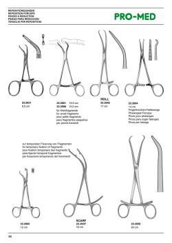
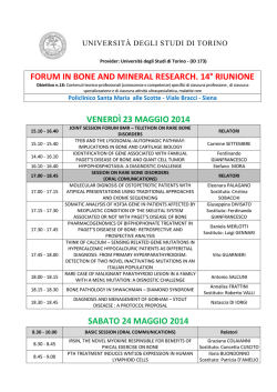
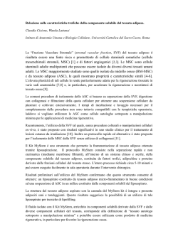
F. Libonati, Roma, Italia, 1-3 Luglio 2013; ISBN 978-88-95940-47-2
Realization of a bone-inspired composite by means of a biomimetic
approach
F. Libonati
Department of Mechanical Engineering, Politecnico di Milano, Milano (Italy)
[email protected]
ABSTRACT. Biomimetics, a design approach to create new structures inspired to natural smart systems, is widely
used as an engineering method for the design of new materials. Indeed, in nature you can find many examples
of smart structures, which can be easily copied. Id est, bone is an interesting material with a hierarchical
organization, showing an optimal combination of mechanical properties, and characterized by a remarkable
toughness, in spite of its brittle mineral components. Indeed, it is generally considered as a biomimetic model,
that can be mimicked to build new bio-inspired materials. Here we present the design, realization and testing of
a new composite material, which mimics the microstructure of human bone, by using a biomimetic approach.
The bone-inspired composite is a synthetic composite made of glass and carbon fibers impregnated into an
epoxy matrix, and showing an internal organization aimed at reproducing the main structural features,
characteristic of the microstructure of cortical bone (i.e. osteons). We perform a complete characterization of
this material, along with that of a classical laminate, designed to make a comparison. After testing the new
material, we also propose new solutions to improve the initial design, based on the results of the experimental
tests and on numerical simulations previously performed on bone nanocomposites models.
SOMMARIO. La biomimetica, intesa come metodo di progettazione per la realizzazione di nuovi materiali ispirati
a strutture biologiche, è sempre più utilizzata in ambito ingegneristico per il design di materiali innovativi. In
natura, infatti, è possibile trovare molti esempi di strutture ottimizzate, facilmente riproducibili con nuove
tecnologie. Ne è esempio l’osso umano che, pur essendo uno dei più antichi e diffusi materiali in natura, è
tuttora oggetto di studio da parte di molti ricercatori. L’ottima combinazione di proprietà di questo materiale, lo
rende tutt’oggi un modello biomimetico, al quale molti ricercatori si ispirano per il design e l’ingegnerizzazione
di nuovi materiali. Questo lavoro mostra il processo di progettazione e realizzazione di un composito
biomimetico ex novo, costituito da fibre di vetro e carbonio in matrice epossidica, ma caratterizzato da una
organizzazione interna innovativa, ispirata alla microstruttura dell’osso umano. Segue una completa
caratterizzazione del neo-materiale e di un laminato tradizionale, usato per eseguire un confronto. Infine, sulla
base dei risultati delle prove sperimentali e di analisi numeriche eseguite su nanocompositi di osso, si
propongono nuove soluzioni, volte a migliorare il design iniziale del composito bio-ispirato.
KEYWORDS. Biomimetic; Bone; Design; Osteon; Bone-inspired Composite; Laminate.
INTRODUCTION
R
esearchers continuously find inspiration throughout nature for the design of innovative structures and materials,
to solve technical issues. Indeed, in nature it is possible to find many examples of smart structures, to be
reproduced with the aid of recent technologies: the hierarchical structure of the gecko foot, which inspired new
99
F. Libonati, Convegno Nazionale IGF XXII, Roma, Italia, 1-3 Luglio 2013, 99-108
self-dry adhesives [1-3], the shark scales inspiring the realization of a low-drag fabric for high performance engineered
swim suits [4], the hooking system of the burdock plant, which led in 1955 to the invention of Velcro as fastening device
[5], the “brick-and-mortar” structure of nacre, which provides the idea for the design of new bio-inspired nacre-like
nanocomposites [6-10]. These are examples of biomimetics, a design approach to create new structures inspired to natural
smart systems, widely used as engineering method for the design of novel materials. Biomimetics has an interdisciplinary
characteristic, allowing a communication among various disciplines, e.g. biology, physics, chemistry, engineering, with the
common interest of solving technical issues.
Figure 1: Schematic representation of the biomimetic approach: (a) Bone tissue at macroscale with evidence of bone cortical (i.e.
dense) and spongy (i.e. porous or foam-like) tissue. (b) Microstructure or Haversian structure of bone, characterized by cylindrical
structures called osteons, which surround the blood vessels; the features reproduced in the bio-inspired material are color-highlighted.
(c) Design of the bio-inspired composite that mimics the organization level represented in (b); the main structural features are colorhighlighted, with the same colors adopted in (b). (d) SEM images of the internal structure of the bio-inspired composite. (e) Bone
nanocomposite models, consisting of tropocollagen molecule and hydroxyapatite crystals, for molecular dynamics simulations. (f) New
design solutions for the bio-inspired composite.
Among biological materials, wood, bone, nacre are considered interesting structural materials, for the load-bearing
capacity. Bone, which provides support for many organisms, is particularly attractive, having been object of research for
many years. It is generally considered as a structural biological composite, made of two distinct materials: a hard mineral
component, made up of hydroxyapatite crystals, embedded into a soft organic matrix, mainly consisting of collagen
molecules. However, what is interesting about bone is the characteristic hierarchical organization, which is thought to be
responsible of the optimal combination of mechanical properties of this material, in particular the remarkable toughness,
regardless its brittle mineral components. In fact, bone toughness is about three to five orders of magnitude more than
that of its constituent mineral. It is interesting to see that no man-made composite material has reached such an
amplification in toughness, with respect to the raw constituents it is made of.
Can bone serve as a biomimetic model to create new composites with an improved toughness? Is it possible to reproduce
the toughening mechanisms, characteristic of bone, in bone-like synthetic materials? To answer these question we
consider bone as a biomimetic model, whose structure can be mimicked to build new bio-inspired composites. The aim is
to replicate, in the new material, some of the toughening mechanisms occurring in bone microstructure.
Here we present the design, realization and testing of a new composite material, inspired to the microstructure of human
bone, by using a biomimetic approach as schematically represented in Fig. 1. The bone-inspired composite is a synthetic
100
F. Libonati, Roma, Italia, 1-3 Luglio 2013; ISBN 978-88-95940-47-2
material made of glass and carbon fibers impregnated into an epoxy matrix, and showing an internal organization aimed at
reproducing the main structural features occurring at bone micro-level (i.e. osteons). We perform a complete
characterization of this material, along with that of a classical laminate, made of the same type and amount of fibers and
resin, designed for comparative reasons. After testing both the new biomimetic material and the classical laminate, we also
propose new solutions to improve the initial design, based on the results of the experimental tests and on numerical
simulations previously performed on bone nanocomposites.
BACKGROUND
B
one has a complex hierarchical structure consisting of different levels, ranging from the nanoscale to the
macroscale. Each level is characterized by a different internal organization, ensuring adaptation to different
functions and needs [11].
In particular, at each level you can recognize characteristic structural features with particular geometry and size, which
affect the mechanical behavior of bone at all levels [12]. For instance, hydroxyapatite and collagen, which represent the
basic building blocks of all bony tissues, show particular size, geometry and arrangement, affecting the mechanical
performance of bone at nanoscale, and in turn at larger scales. The effect of their size and geometry has been largely
studied. However, the mechanisms occurring at small scales are not clearly understood yet. Indeed, recent advances in
numerical modeling, thanks to the continuous increase in computational power, allows one to reach very small length and
time scales, hence to study nanoscale phenomena, which differ from the continuum ones. Researchers are now trying to
investigate the structure-property relationship, adopting multi-scale approaches.
At larger scales, the structure of bone has been widely studied by means of experimental and numerical testing [13-16]. At
microscale, the microstructure of bone has been characterized by performing experimental measurements under different
loading conditions (i.e. tension, compression, bending and torsion)[17-20], confirming a marked anisotropic behavior,
owing to the internal organization. Indeed, bone microstructure is characterized by the presence of a repeating unit with a
cylindrical shape, the osteon. Each osteon consists of concentric lamellae with an internal canal (i.e. Haversian canal),
ensuring the primary body flow. The elongated osteon shape and the predominant longitudinal orientation of fibers in
each osteon, make bone strongly anisotropic. In Fig. 2a we show the microstructure of the human bone, colorhighlighting the structural features reproduced in the biomimetic design.
The optimal combination of mechanical properties, characteristic of bone, is due to an ensemble of mechanisms occurring
at different scale levels. For instance, the remarkable toughness of bone is due to a combination of intrinsic and extrinsic
toughening mechanisms, occurring below and above the micro-scale level, respectively [12]. Intrinsic toughening
mechanisms include molecular uncoiling and unfolding, and intermolecular sliding, and are observed at nanoscale level.
Indeed, they directly affect the behavior of collagen molecules and of mineralized fibrils. Extrinsic toughening
mechanisms, occurring in the range of 10-100 ߤm, include crack deflection and twisting, which occur at osteon-osteon
interface, constrained microcracking and crack bridging by uncracked ligaments, activated by the formation of
microcracks [21]. The formation of microcracks, especially at cement lines, which are the regions at interface between two
osteons, toughens bone, due to a local release of high stresses. The deflection and twist of a crack, caused by the presence
of osteons, gives a major contribution to the increase of bone toughness, by inhibiting the crack growth process,
increasing the dissipation capacity [13, 22]. Indeed, osteons are thought to play a main role in crack deflection, along with
their outer boundaries (i.e. cement lines), which are preferential sites of micro-cracks nucleation [14].
Here, we adopt the microstructure of cortical bone, also known as secondary or Haversian structure, as a biomimetic
model to be reproduced in a new composite material. The aim is to mimic the crack deflection mechanisms, occurring in
bone tissue.
MATERIALS AND METHODS
From Design to Manufacturing
W
e select the main structural features of bone microstructure, the osteons, to be replicated in a new composite
material, as shown in Fig. 2, which shows the microstructure of cortical bone, highlighting the elements
mimicked in the bio-inspired composite, and the schematic of the biomimetic design of the new material. We
adopt bundles of UD-GF, which offer resistance to torsional loadings to mimic the osteons. We reproduce the osteon
outer boundaries (i.e. cement lines) with sleeves made of ±45°-CF, with the function of collecting and packing each
101
F. Libonati, Convegno Nazionale IGF XXII, Roma, Italia, 1-3 Luglio 2013, 99-108
osteon, also preserving the fiber alignment. Besides offering bending strength, these tubular layers aim to reproduce one
of the main properties of bone: the possibility of deflecting and twisting cracks. To mimic the interstitial lamellae we use
longitudinal UD-GF impregnated into an epoxy matrix, offering compactness and filling up the gaps between osteons.
Then, we adopt two layers of UD-GF-NCF to reproduce the outer circumferential system (i.e. circumferential lamellae),
which packs the osteon architecture in human cortical bone. The two skins of UD-GF-NCF are placed at the top and
bottom of the composite, to compact the internal tubular structure and offer a flat and uniform surface to the composite
plate. We introduce many simplifications in the design phase: some simplifications are due to that our bio-inspired
material is a synthetic material, unlike human bone, hence living functions cannot be provided by that. For instance, we do
not replicate the Haversian canal, responsible of the primary bloody flow, and the canaliculi, small canals responsible of
the secondary bloody flow. Moreover, we introduce other simplifications to make the design feasible with the available
manufacturing tools.
The main simplifications regards: i) the osteons number and dimensions (about 1 order of magnitude, between the osteon
diameter size, 100-200 ߤm, and the sleeves diameter size, 4-5 mm), ii) the fibers orientations, longitudinal in the bioinspired composite and with multiple orientation in the concentric lamellae of the osteons, iii) the external lamellae and
the cement lines, here simplified with a ±45°-CF sleeves, iv) the shape of the final structure (from cylindrical to flat), and
v) the interstitial lamellae, simplified with bundles of UF-GF impregnated into an epoxy resin.
These simplifications are due not only to manufacturing reasons, but also to ensure a larger variety of applications of these
composite panels in the structural field.
Beside the bio-inspired material, we also produce another laminate, to allow a direct comparison with the newly designed
material. The comparative material contains the same type and amount of fibers and resin, but it is a laminated composite
with the following lay-up: [GF-(0°)4, CF-(±45°)2, GF(0°), CF-(±45°)]s. The GF outer layers and the CF layers are both
NCF, whereas the internal layer of GF are UD fibers. Both the materials contain 54 % vol. fibers, consisting of about 6.5
% vol.-CF and 47.5 % vol.-GF.
(a)
(b)
Figure 2: (a) Microstructure of the human bone; color-highlighted the structural features reproduced in the biomimetic design. (b)
Internal structure of the bio-inspired composite: the main structural features are color-highlighted, with the same colors adopted in (a).
Circumferential lamellae are reproduced with bundles of UD-GF, cement lines with ±45°-CF sleeves, interstitial lamellae with UD-GF
impregnated into epoxy resin. The circumferential outer system, which packs the internal osteon-like structure in cortical bone, is
replaced in the biomimetic design by a flat one, where two NCF have the function of compacting the internal tubular architecture,
offering a flat and uniform surface to the final composite material.
From Design to Manufacturing
Both composite materials are manufactured in the laboratory of Clausthal University of Technology. The manufacturing
process to create the bio-inspired material includes: sleeves cutting, sleeves filling with UG-GF, the placement of UD-GF
by means of a sewing frame, the stitching step and finally, the removal of the sewing frame. Then, to correctly fill up the
panels with resin, allowing a good surface finishing, we adopt a new system of resin injection, based on vacuum infusion
process and resin transfer molding. Being this new manufacturing technique manual, we should take into account the
presence of many defects in the end-products. The assembly of the tubular structures and their filling with UD-GF, by
preserving the correct fibers alignment, makes the manufacturing process of the bio-inspired composite far more
complicate than that of the conventional laminate. Indeed, the manufacturing process of the comparative laminate is also
manual, but less complicate. It consists of a manual lamination, layer by layer. UD-GF are placed by filament winding,
followed by the placement of CF-NCF, and the placement of UD-GF-NCF at the top and bottom to ensure flat surfaces.
Finally the resin infusion occurs through a vacuum pump and a mold, then curing. Fig. 3 shows the manual lamination
process of both materials, the bio-inspired and the laminated composite.
102
F. Libonati, Roma, Italia, 1-3 Luglio 2013; ISBN 978-88-95940-47-2
(a)
(b)
Figure 3: Lamination process: (a) Placement of UD-GF by means of a sewing frame during the lamination of the bio-inspired
composite and, highlighted, the particular of the osteon-inspired tubular structure; (b) Filament winding during the lamination of the
comparative composite laminate.
Mechanical Characterization
We perform a complete characterization of both the bio-inspired and the laminated composites under static loads. Being
both materials anisotropic, we carry out tests in longitudinal and transversal directions. Indeed, we cut rectangular
specimens in two orthogonal directions from the manufactured plates. The size of samples, chosen by following the
standards, is different for each type of tests.
We perform: i) Tensile tests, according to ASTM D 3039/D3039M-08 [23], with a cross-head speed of 2 mm/min and a
data acquisition frequency of 5 Hz; ii) Compressive tests, following ASTM D 3410/D 3410M-03 [24], with a cross-head
speed of 1.5 mm/min and 5 Hz as data acquisition frequency; iii) Flexural bending tests, adopting a three-point bending
configuration, according to UNI EN ISO 14125 [25], with a cross-head speed of 2 mm/min and 5 Hz as data acquisition
frequency; here we use a deflectometer (MTS model 632-06H-30) to measure the mid-span deflection, and two lateral
supports to limit transversal displacements of the load bearing rolls used as support; iv) Translaminar fracture toughness
tests, according to ASTM E1922-04 [26], using a cross-head speed of 1 mm/min; here we apply the load through pinloading clevises and we measure the displacement at the notch mouth by using a displacement gage attached to the
specimen through knife edges; v) Interrupted translaminar fracture toughness tests; these tests are similar to those of case
iv), but the load is applied monotonically, and interrupted at each 0.5 kN step for few minutes, to allow microscopic
analyses. To get microscopic images we adopt an optical microscope, endowed with LEICA DFR 290 lens, and a
computer with a software for image acquisition. To better understand the effect of the osteon structure, we create notches
with different initial lengths and with the crack tip ending in both inter-osteon and intra-osteon regions.
For tensile, compressive, and flexural bending tests we use rectangular specimens, with adhesively bonded tabs for the
first two types of tests. To carry out translaminar fracture toughness tests, we use single-edge-notch ESE(T) specimens in
opening mode loading, where the narrow notch is created by means of a diamond impregnated copper saw.
We also analyze the cross sections of the specimens subjected to translaminar fracture toughness tests, by means of an
SEM Evo 50 EP Zeiss by Oxford Instrument. We cut the specimens in the vicinity of the zone, where the crack has
previously propagated, and we observe the cross sections with an SEM. Before microscopic analyses, we clean the sample
surfaces and make them electronically conductive, by sputter-coating with a conductive material (i.e. gold).
Numerical simulations
In previous works [27, 28] we perform molecular dynamics simulations, on bone nanocomposite models and bone
building blocks with the aim of studying nanoscale phenomena occurring in bone and bone-like materials. The goal is to
get an insight into the material behavior and to investigate the characteristic mechanisms, which determine the bone
remarkable properties. Moreover, the results can get important advices for the improvement of our first biomimetic
design. We investigate the effect of confinement on the mechanical properties and in particular on the fracture behavior
of the mineral crystals of bone. We find that, by reducing the crystals size, the material shows a change in the fracture
response, from a brittle mode in large samples, to a quasi-ductile mode in smaller samples. Indeed, the small samples are
characterized by larger strains at breakage, compared to larger samples, and the failure mode is not due to the propagation
of a main crack, but to the interaction of many small cracks and defects. Also, small samples are characterized by a quasihomogeneous stress distribution, showing no stress concentration at crack tip, and large failure stresses, comparable to
those of uncracked samples. This flaw tolerant behavior occurs at nanoscale, below a critical size, which is found to be
around 4.15 nm, similar to the size of HAP crystals in human bone [12, 29-31]. Furthermore, we study the role of
collagen-HAP interface on the mechanical properties of collagen-HAP nanocomposite models [28] and we observe a
positive effect of confinement, which increases the performance of collagen-hydroxyapatite as an integrated system. Our
103
F. Libonati, Convegno Nazionale IGF XXII, Roma, Italia, 1-3 Luglio 2013, 99-108
findings confirm previous studies [32, 33], where the authors state that not only the building blocks make bone so
resilient, but at an atomistic and molecular scale, the size effect plays a main role in determining the mechanical behavior
of bone, leading to new phenomena, not occurring at larger levels. We also discover the key role played by intermolecular
hydrogen bonds, in determining the resistance against slip. These bonds, occurring within the collagen helix and between
the collagen and the hydroxyapatite, act as sacrificial bonds: the continuous formation and breakage of such bonds is an
important energy dissipation mechanism, which leads to an increase in the nanocomposite toughness. These results may
provide details on the mechanism of load transmission inside collagen fibrils and fibers, and mineralized tissues, which is
crucial for the development of constitutive models of collagenous tissues at larger scales. Moreover, these models might
have many applications, ranging from tissue engineering studies to the development of bio-inspired materials. The
understanding of the mechanisms and the nature’s secrets governing the interaction and the behavior of collagenhydroxyapatite nanocomposites can shead light in the design of the bone-inspired composite, leading to an improvement
in the initial proposed design.
RESULTS AND DISCUSSION
W
e observe a good repeatability of the results for each material. However, the behavior of the studied materials is
completely different, in particular the failure mode, owing to the different internal organization. For the sake of
brevity we do not represent all the stress-strain curves obtained from each test, but we present the final results
in Tab. 1.
Longitudinal
Property
Tensile strength
Compressive strength
Flexural strength
Tensile modulus
Compressive modulus
Flexural modulus
Translaminar fracture toughness
Fracture strength*
Unit
Bio-inspired
MPa
797
MPa
416
MPa
880
MPa
46486
MPa
↑
MPa
44296
MPa√m
26.87
MPa
379
Comparative
568
581
782
33245
↓
31108
32.68
452
Transversal
Bio-inspired
28
101
59
14558
↓
10585
-
Comparative
65
157
156
12366
↑
14583
-
*Failure stress for cracked samples.
Table 1: Results of experimental tests carried out in longitudinal and transversal directions, on the bio-inspired composite and on the
composite laminate.
The bio-inspired composite generally performs better in longitudinal direction, thanks to the osteons elongated shape,
which enhances the longitudinal properties. Indeed, it shows a higher stiffness, under tensile, compressive and bending
loading, and a higher strength under tensile and bending loading, than the composite laminate. The classical laminate used
for comparison performs better in transversal direction. This is due to the interplay of the various layers, which cooperate
to ensure resistance to transversal failure. In the bio-inspired composite the weakest part, which is the first to fail under
transversal loading conditions, is the interface between two osteons. By observing the failure mode we can recognize a
splitting mechanism between two osteons, which characterizes the bio-inspired material. For the composite laminate
instead, failure develops layer by layer. Fig. 4 shows a comparison between failure mechanisms occurring in both materials
under transversal bending loading.
104
F. Libonati, Roma, Italia, 1-3 Luglio 2013; ISBN 978-88-95940-47-2
(b)
(a)
Figure 4: Flexural bending tests in transversal direction: (a) failure mode of the bio-inspired composite; (b) failure mode of the
composite laminate.
The cooperation of the various layers also seems to play a main role in determining the translaminar fracture toughness
and the fracture strength. Indeed, the composite laminate shows a slightly better response in presence of crack, with a
translaminar fracture toughness and a fracture strength, 18% and 16% respectively higher than the bio-inspired
composite. The presence of a crack affects the strength of the bio-inspired composite, by reducing it to less than a half. In
the case of conventional composite, instead, the strength of the material in presence of a crack is 20% less than the
correspondent flawless material. The lower value of the translaminar fracture strength in the bio-inspired material is due
to predominant longitudinal reinforcement. Also, being the ±45°-CF in a tubular shape, they do not contribute to prevent
the crack growth, as the ±45°-CF textiles (i.e. NCF) do in the comparative laminate. It seems that an inter-osteon
reinforcement, keeping the sleeves together and allowing them to work as a unique system, inhibiting the crack growth, is
missing. The bio-inspired material behaves as a discrete system, showing a lack of continuity between the osteons.
Nevertheless, the bio-inspired material can replicate the typical phenomena acting - as toughening mechanisms - at bone
micro-level (i.e. crack deviation and longitudinal splitting). Fig. 5 shows a comparison between the failure mode of the bioinspired material and that of the comparative one, after a translaminar fracture toughness test. In the comparative
material, failure occurs due to fiber-matrix debonding and delamination, whereas in the bio-inspired material the crack
seems to propagate at interface between two osteons, leading to a crack splitting phenomenon. This hypothesis is also
confirmed by the results obtained from microscopic analyses.
(a)
(b)
Figure 5: Comparison between the fracture behavior of the bio-inspired composite and that of comparative material: the crack path is
highlighted with a red dashed line. (a) Bio-inspired composite: failure by crack splitting. (b) Comparative laminate: failure by crack
propagation and damage area ahead the crack tip.
In particular, images from the interrupted fracture toughness tests allow the fracture process to be followed, observing
crack formation and propagation. Fig. 6 shows the microscopic images, after each load step of an entire test. During the
tests, we observe the formation of many cracks, highlighted in Fig. 5(a)-(e) with red dashed lines, whereas the main cracks,
causing longitudinal splitting and leading to failure, are highlighted in Fig. 5(f) with yellow dashed lines.
For the tested specimens, notches have different initial lengths, with the crack tip ending in both inter-osteon and intraosteon regions. In the former case, the crack directly propagates along osteon-osteon interface, whereas in the latter, the
crack first propagates inside the osteon, then it deviates along osteon-osteon interface, leading to longitudinal splitting.
These hypotheses, made on the basis of the observations performed with the optical microscope, are also confirmed by
SEM analyses. The results of SEM analyses are shown in Fig. 7; the images are referred to the cross section of a sample of
bio-inspired composite, and show the region where the main crack propagates. In this figure the phenomenon of crack
105
F. Libonati, Convegno Nazionale IGF XXII, Roma, Italia, 1-3 Luglio 2013, 99-108
deviation is clearly visible: the crack initially propagate inside the osteon, then deviates, once the outer boundary has been
reached. This mechanism is similar to what occurs in bone at microscale, with crack deviation at cement lines.
Figure 6: Images from an optical microscope showing the region near the crack tip, during an interrupted fracture toughness test on
the bio-inspired composite. The red dashed lines in subfigures (a)-(e) show the cracks formation and propagations; the yellow dashed
lines in subfigure (f) show the main cracks propagations, leading to splitting.
(a)
(b)
Figure 7: SEM images from backscattered electrons showing a cross section of a sample of bio-inspired material. (a) The image
(magnitude 40X) shows the region where the main crack propagates; the crack region is highlighted with a red dashed line circle. (b)
The image (magnitude 100X) shows the crack deviation, from the intra-osteon to the inter-osteon region; the crack path is highlighted
with a red dashed line.
REMARKS AND PERSPECTIVES
I
n this paper, we show the design of a new bio-inspired composite, by means of a biomimetic approach, including
manufacturing, characterization, and comparison with a conventional composite. The new designed biomimetic
composite has a different mechanical behavior to the conventional one, due to the different internal organization. In
particular, the bio-inspired structure shows a marked anisotropic behavior, with improved properties (i.e. stiffness and
strength) in longitudinal direction (parallel to the osteon main axis), except for compression strength. In transversal
direction it shows some drawbacks, though maintaining a higher stiffness under tensile loading. However, the bio-inspired
material has shown to replicate the typical toughening mechanisms occurring in human bone. The microscopic analyses,
performed with an optical microscope and with an SEM, have shown the occurrence of crack deviation and splitting in
the bio-inspired material, similarly to what occurs in human bone. Hence, despite its shortcomings, mainly due to lack of
continuity or reinforcement in the inter-osteon region, the newly designed material can mimic the typical bone fracture
mechanism. We show the first design solution for a new bio-inspired materials, along with its strong and weakest points.
Then, by observing the Haversian structure of bone and the mechanical behavior of the first proposed solution, we realize
that the weakest point of the bone-like composite is the mechanical response in transversal direction. Therefore, to
106
F. Libonati, Roma, Italia, 1-3 Luglio 2013; ISBN 978-88-95940-47-2
improve the transversal behavior we need to enhance osteon-osteon interactions, for instance by creating a multi-layer
osteon structure, allowing simultaneous inter-osteon interactions in different directions (see Fig. 8b). Another possible
solution can be given by the addition of a weave composite fabric, alternatively placed under and over each osteon (see
Fig. 8c). Schematics of the initial solution and of some proposed improved solutions are given in Fig. 8.
As future perspective, we aim to introduce further improvements in the initial proposed design, to overcome the limits in
transversal response and to further improve fracture strength, leading to a biomimetic solution with high performance. In
view of the obtained simulation results [28], the proposed design could be optimized, by adding reinforcing nanostructural platelet elements with proper aspect ratio and characteristic sizes, as suggested by the molecular dynamics
simulations in [27, 28]. These nanoparticles could reproduce the stiffening and toughening effects given by hydroxyapatite
platelets in bone. Furthermore, since the surface interactions have revealed to play a significant role on the mechanical
behavior of collagen-hydroxyapatite nanocomposite, a "glue-like system", providing "sacrificial local failure", can also be
introduced in the new design to improve interface strength, mimicking the role played by hydrogen bonds and porosity in
bone nanocomposites. Thus, we propose further improvements focused on two main aspects: the enhancement of
interface strength, by using a "glue-like" system, and the inclusion of platelet-like nanoparticles with a high aspect ratio.
These concept are clearly explained in Fig. 9, where a schematic of the proposed solutions is given.
(a)
(b)
(c)
Figure 8: Schematic solutions of the internal structure of the bone-inspired composite. (a) Initial solution object of the present study.
(b) Alternative proposed solution: multi-layer osteon structure. (c) Alternative proposed solution: inter-osteon woven layer to improve
the osteon-osteon interactions, limiting their slipping.
(a)
(b)
Figure 9: Schematic solution based on the results of atomistic simulations. (a) Representation of the osteon structure with improved
adhesion at interface and platelet-like nanoparticles, inspired to the hydroxyapatite crystals. (b) Section of the osteon-like sleeve
surrounded by platelet-like nanoparticles.
ACKNOWLEDGEMENTS
T
he authors would like to thank Prof. Ziegmann and PhD Sonja Niemeyer from TU Clausthal, for the effort in the
manufacturing phase of the composite plates used for this study.
REFERENCES
[1] E. Arzt, S. Gorb, R. Spolenak, In: Proceedings of the National Academy of Sciences, 100 (2003) 10603.
[2] K. Autumn, Y. A. Liang, S. T. Hsieh, W. Zesch, W. P. Chan, T. W. Kenny, R. Fearing, R. J. Full, Nature, 405 (2000)
681.
[3] K. Autumn, M. Sitti, Y. A. Liang, A. M. Peattie, W. R. Hansen, S. Sponberg, T. W. Kenny, R. Fearing, J. N.
Israelachvili, R. J. Full, In: Proceedings of the National Academy of Sciences, 99 (2002) 12252.
107
F. Libonati, Convegno Nazionale IGF XXII, Roma, Italia, 1-3 Luglio 2013, 99-108
[4] B. Bhushan, Beilstein Journal of Nanotechnology, 2 (2011) 66.
[5] G. de Mestral, Improvements in or relating to a method and a device for producing a velvet type fabric, Switzerland
Patent, (1955).
[6] K. Okumura, P. G. de Gennes, The European Physical Journal E, 4 (2001) 121.
[7] S. F, S. Ak, B. Yl, Biomaterials, 24(2003) 3623.
[8] R. Z. Wang, Z. Suo, A. G. Evans, N. Yao, I. A. Aksay, J. Mater. Res., 16 (2001) 2485.
[9] Z. Y. Tang, N. A. Kotov, S. Magonov, B. Ozturk, Nature Materials, 2 (2003) 413.
[10] H. D. Espinosa, J. E. Rim, F. Barthelat, M. J. Buehler, Progress in Materials Science, 54 (2009) 1059.
[11] B. Bhushan, Philosophical Transactions of the Royal Society A: Mathematical, Physical and Engineering Sciences,
367 (2009) 1445.
[12] M. E. Launey, M. J. Buehler, R. O. Ritchie, Annual Review of Materials Research, 40 (2010) 25.
[13] R. K. Nalla, J. H. Kinney, R. O. Ritchie, Nature Materials, 2 (2003) 164.
[14] R. K. Nalla, J. J. Kruzic, J. H. Kinney, R. O. Ritchie, Biomaterials, 26 (2005) 217.
[15] K. J. Koester, J. W. Ager, R. O. Ritchie, Nature Materials, 7 (2008) 672.
[16] P. L. Mente, J. L. Lewis, Journal of Orthopedic Research, 7 (1989) 456.
[17] A. Ascenzi, E. Bonucci, The Anatomical Record, 158 (1967) 375.
[18] A. Ascenzi, E. Bonucci, Calcified Tissue Research, 2 (1968) 44.
[19] A. Ascenzi, P. Baschieri, A. Benvenuti, Journal of Biomechanics, 23 (1990) 763.
[20] A. Ascenzi, P. Baschieri, A. Benvenuti, Journal of Biomechanics, 27 (1994) 875.
[21] R. O. Ritchie, M. J. Buehler, P. Hansma, Physics Today, 62 (2009)41.
[22] M. A. Meyers, P. Y. Chen, A. Y. M. Lin, Y. Seki, Progress in Materials Science, 53 (2008) 1.
[23] D3039/D3039M-08, Standard Test Method for Tensile Properties of Polymer Matrix Composite Materials, ASTM,
(2008).
[24] D3410/D3410M-03, Standard Test Method for Compressive Properties of Polymer Matrix Composite Materials with
Unsupported Gage Section by Shear Loading, ASTM, (2008).
[25] 14125, Fibre-reinforced Plastic Composites - Determination of Flexural Properties, UNI EN ISO, (2011).
[26] E1922-04, Standard Test Method for Translaminar Fracture Toughness of Laminated and Pultruded Polymer Matrix
Composite Materials, ASTM, (2010).
[27] F. Libonati, A. K. Nair, L. Vergani, M. J. Buehler, Journal of the mechanical behavior of biomedical materials, 20,
(2013) 184.
[28] F. Libonati, Bio-Inspired Composite Materials: From Human Bone to Bone-Like Composites, Department of
Mechanical Engineering, Politecnico di Milano, Milano, (2013).
[29] J. Y. Rho, L. Kuhn-Spearing, P. Zioupos, Medical Engineering & Physics, 20 (1998) 92.
[30] S. Weiner, H. D. Wagner, Annual Review of Materials Science, 28 (1998) 271.
[31] Y.-Y. Hu, A. Rawal, K. Schmidt-Rohr, In: Proceedings of the National Academy of Sciences, 107 (2010) 22425.
[32] H. Gao, B. Ji, I. L. Jäger, E. Arzt, P. Fratzl, In: Proceedings of the National Academy of Sciences, 100 (2003) 5597.
[33] G. E. Fantner, T. Hassenkam, J. H. Kindt, J. C. Weaver, H. Birkedal, L. Pechenik, J. A. Cutroni, G. A. G. Cidade, G.
D. Stucky, D. E. Morse, P. K. Hansma, Nature Materials, 4 (2005) 612.
108
© Copyright 2026 Paperzz