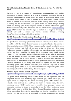
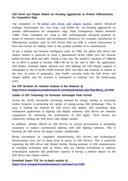
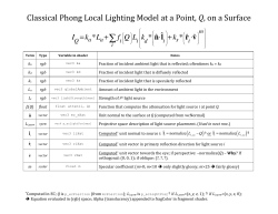
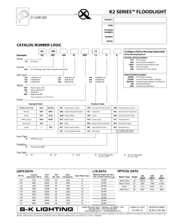
Arpool L Specifications
Send
Ordering Information1
FX AL
Power
Color
Optics
12
Housing
Model
Power
Color
Optics
Voltage
Housing2
FX AL
H
L
40
RGB
SP
FL
12
FT
FF
FW
TL
Specify remote power supply separately below. 3See page 2 for instalation details.
1
Luminaire
n
Flange Tiles / Flange Liner /
Flange Thin Wall
9.37”ø
(238mm)
n
Underwater LED with high performance
optics. Glass lens creates optical effect
of narrow and wide beam.
UL STD 676, submersible (only),
pool and fountain applications,
max depth 10’
n
Remote power supply
n
Stainless steel construction 316L
marine grade, with clear tempered glass
n
Installation housing, stainless steel
316L marine grade construction,
direct concrete pour
n
Supplied with oil and water resistant
14’ feed cable standard, single color
18/2 AWG, RGB 18/4 AWG
Dimensions
3.74”
(95mm)
.47”
(12mm)
Trimless
Power
n
H = 65W, 4000K,6045 lm
n
L = 33W, 4000K, 2790 lm
n
H = 65W, RGB:
R 1218 lm, G 1743 lm, B 525 lm
n
L = 33W, RGB:
R 638 lm, G 913 lm, B 275 lm
Color Temperature
n
40 = 4000K
nRGB
n
2 Step MacAdam
n
CRI: > 83
Optics
n
SP = spot - 10 degree
n
FL = flood - 30 degree
n
9.37”ø x 4.25” (238mm x 110mm)
flange tiles
Voltage
n
9.37”ø x 4.25” (238mm x 110mm)
flange liner
Housing2
n
9.37”ø x 4.25” (238mm x 110mm)
flange thin wall
n
FT = flange tiles (tile/concrete)
n
FF = flange liner (liner insert)
n
FW = flange thin wall
(stainless or similar surface)
n
TL = trimless
n
9.17”ø x 4.25” (233mm x 110mm)
trimless
n
12 = 12VDC fixture voltage
Power Supply3 (Remote)
9.17”ø
(233mm)
Non-Dim
D-520-12006: LED Driver, Lightech, Non-Dim,
25W, 12V, 120/277V, No enclosure.
D-520-12009: LED Driver, Lightech, Non-Dim,
100W (Class 1), 12V, 120/277V, No enclosure.
Dim
IL-JB-LED-12004-120V-DFPN: LED Driver,
Lutron Hi-Lume A Series, Forward Phase
(with neutral) 1% dimming, 5W-40W, 12V,
120V, Supplied in a Dry location enclosure.
4.44”
(113mm)
IL-JB-LED-12007-UNV-D3W: LED Driver,
Lutron Hi-Lume A Series, 3-Wire fluorescent
1% dimming, 5W-40W, 12V, 120/277V, Supplied
in a dry location enclosure.
IL-JB-LED-12007-UNV-DES: LED Driver,
Lutron Hi-Lume A Series, EcoSystem 1%
dimming, 5W-40W, 12V, 120/277V, Supplied
in a dry location enclosure.
RGB
D-550-20003: EldoLED LIN100D2, CV
12/24V DMX/Sequencer Interface for RGB
fixtures, 1.3A Max per output RGB@12V, 2A
Max per output RGB@12V, Requires a NonDim 12V CV driver ordered separately, DMX
Control ordered separately. No enclosure.
See power supply pages for details. No enclosure, unless stated. lm80 values shown.
3
IP68
410 381 1497 inter-lux.com [email protected]
Inter-lux reserves the right to make technical changes without notice.
# 930-3016 (rev 1)
1
Arpool L Dimensions
Fixture + housing
Flange Tiles (FT)
ø 9.37”
(238mm)
3.74”
(95mm)
Flange Thin Wall (FW)
Flange Liner (FL)
0.47”
(12mm)
ø 9.37”
(238mm)
ø 9.37”
(238mm)
3.74”
(95mm)
0.47”
(12mm)
3.74”
(95mm)
0.47”
(12mm)
Trimless Tiles (TL)
ø 9.17”
(233mm)
3.66”
(95mm)
Marine grade stainless steel 316L fixture
7/8 (23mm) conduit connector
410 381 1497 inter-lux.com [email protected]
Inter-lux reserves the right to make technical changes without notice.
# 930-3016 (rev 1)
2
Arpool L Power Supplies
Single Color Drivers
Qty.
Case
Nominal Input
Voltage (V)
Nominal Input
Current (A)
Power
Factor
Output Power
Range (W)
Dimming
Mode
Dimming
Control
Dimming
Range
Location
Rating
Lightech 25W
1
120
277
0.11
0.3
0.98
1-25
N/A
N/A
N/A
Dry
D-520-12009
Lightech 100W
2
120
277
1.3
0.5
0.98
1-100
PN/A
N/A
N/A
Dry
IL-JB-LED-12004120V-DFPN
Hi-Lume A Series
LED LTE
3
120
0.38
0.99
5-40
PWM
Forward phase
with neutral
1 –100%
Dry
IL-JB-LED-12007UNV-D3W
Hi-Lume A Series
LED L3D, 3-wire
3
120
277
0.38
0.17
0.99
0.96
5-40
PWM
3-Wire
1 –100%
Dry
IL-JB-LED-12007UNV-DES
Hi-Lume A Series
LED L3D, EcoSystem
3
120
277
0.37
0.17
0.99
0.96
5-40
PWM
Ecosystem®
1 –100%
Dry
Part Number
Description
D-520-12006
Although it is possible to exceed the remote mounting distance, the installer and/or end user must take precautions to prevent and/or test the effects of EMI (electromagnetic interference).
Case dimensions
Case 1 (no enclosure)
Case 2 (no enclosure)
1.65”
1.2”
8.27”
5.24”
9.06”
1.57”
2.56”
Case 3 Hi-Lume, case K (enclosure supplied)
3.0”
(76mm)
1.38”
(35mm)
4.2”
(107mm)
0.64”
(16mm)
1.0”
(25mm)
2.0”
4.42”
(36mm)
1.99”
(51mm)
4.6”
(117mm)
0.88”
(22mm)
4.9”
(124mm)
9.0”
3.5”
4.5”
supplied in dry
location enclosure
1.53”
(39mm)
Wiring Diagram for Forward Phase Control
White (N)
Black (L)
Black (L)
White (N)
White (N)
LTE
(forward phase with neutral)
Wiring Diagram for Forward Phase Control
Red (+)
Power Supply
(non-dim)
Power Supply
(non-dim)
Power
Supply
(non-dim)
Red (+)
Red (+)
Blue (-)
Blue (-)
Blue (-)
To Forward
To Forward
Phase
To Phase
Forward
Control
Control
Phase Control
Black (L)
Maximum wiring distance*
Load per driver
Wiring
Diagram
Forward Phase Control+V
Dimmed
Hotfor
(Black)
Neutral (White)
Hi-lume®
A-Series
LED light
engine
Dimmed Hot (Black)
Dimmed
Hot (Black)
Ground (Green)
Neutral (White)
Neutral (White)
Hi-lume®
Ground
A-Series
Hi-lume®
A-Series
LED light
engine
LED
light
Osram
+V
-V
+V
engine
-V
Ground (Green)
-V
Ground
Note:
Colors
shown correspond
to terminal blocks on driver.
Ground
(Green)
Ground
Note: Colors shown correspond to terminal blocks on driver.
Note: Colors shown correspond to terminal blocks on driver.
Lutron
Wire gauge
≤48W
≤72W
≤96W
#18AWG
37’
25’
18’
≤40W
15’
#16AWG
59’
39’
29’
25’
#14AWG
95’
63’
47’
40’
#12AWG
151’
101’
75’
60’
#10AWG
241’
160’
120’
—
Voltage drop guide for 12VDC. Actual Voltage drop to
be calculated by installer
*
L3D (3-wire)
L3D (Ecosystem®)
+V
Dimmed Hot (Orange)
LED light
Hi-lume®
engine
A-Series
Switched Hot (Black)
Neutral (White)
+V
Switched
Hot (Black)
-V
+V light
Dimmed Hot (Orange)
LED
Hi-lume®
Ground
(Green)
Ground
engine
Dimmed Hot (Orange)
A-Series
LED
light
Hi-lume®
engine
Neutral (White)
A-Series
-V
Neutral (White)
-V
Ground (Green)
Ground
Note: Colors shown correspond
to terminal blocks on driver.
Ground (Green)
Ground
Note: Colors shown correspond to terminal blocks on driver.
Note: Colors shown correspond to terminal blocks on driver.
Switched Hot (Black)
Wiring Diagram for EcoSystem® Digital Control
Wiring Diagram
for EcoSystem® Digital Control +V
Neutral (White)
To Line
Voltage
Wiring
Diagram
3-Wire Control
Switched
Hot for
(Black)
Wiring Diagram for 3-Wire Control
Wiring Diagram for EcoSystem® Digital Control
To EcoSystem®
To EcoSystem®
To EcoSystem®
To Line
To Line
Digital
Digital
LinkLinkDigital
Link
Voltage
Voltage
Wiring Diagram for 3-Wire Control
To 3-wire
To 3-wire
Dimming
To
Dimming
3-wire
Control
Control
Dimming Control
Wiring diagrams
25W / 100W Non-Dim
Switched
Hot (Black)
Ground (Green)
Switched Hot (Black)
Neutral (White)
Neutral
(White)
E1
(Purple)
Ground (Green)
E2
(Purple)
Ground
(Green)
Hi-lume®
A-Series
LED light
engine
Hi-lume®
Ground
A-Series
Hi-lume®
A-Series
LED light
engine
LED
light
+V
-V
+V
engine
-V
E1 (Purple)
-V
Ground
(Purple)
Note:E1
Colors
shown correspond to
terminal blocks on driver.
E2 (Purple)
Ground
E2 (Purple)
Note: Colors shown correspond to terminal blocks on driver.
Note: Colors shown correspond to terminal blocks on driver.
410 381 1497 inter-lux.com [email protected]
Inter-lux reserves the right to make technical changes without notice.
# 930-3015 (rev 3)
3
Arpool L RGB Interface
RGB Control Interface Details
Qty.
Part Number
Description
Nominal Input
Voltage (V)
Maximum Output
per channel (W)
Output Power
Range (W)
D-550-20003
DMX/Sequencer Interface
12
32
96
RGB Control case dimensions (DMX/Sequencer Interface)
110 mm / 4.33”
23 mm / 0.91”
21.5 mm / 0.85”
ø 4.2 mm / 0.17”
10 mm / 0.39”
TC
DMX in +
DMX in -
Ext in
Ext in +
LED supply +
30 mm / 1.18”
DMX in shield
LedSync thru +
10 mm / 0.39”
LedSync thru LedSync shield
Group 1
50 mm / 1.97”
Group 2
LINEARdrive 100D
Group 3
12-28V / 6A Direct voltage controlled LED driver
Group 4
M
153 mm / 6.02”
Wiring Diagram
{
12/24V
VDC - VDC +
Not connected
TC
DMX in +
DMX in -
DMX in +
DMX in DMX in shield
Ext in
Ext in +
LED supply +
DMX in shield
LedSync thru +
LedSync thru LedSync shield
Group 1
LINEARdrive 100D
12-28V / 6A Direct voltage controlled LED driver
Group 2
Group 3
RGB LED strip
+
R
G
B
Group 4
M
Not connected
See installation / driver instructions for details.
Must order power supply separately
410 381 1497 inter-lux.com [email protected]
Inter-lux reserves the right to make technical changes without notice.
# 930-3001 (rev 3)
4
© Copyright 2026 Paperzz