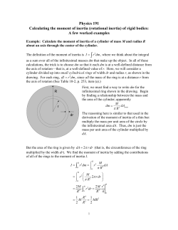
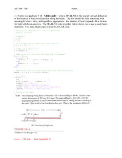
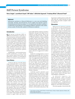
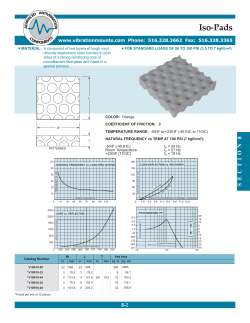
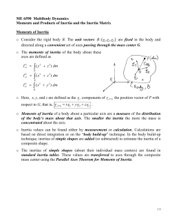
Structures and Stiffness
B. Furman
K. Youssefi
20SEP2007
K. Youssefi and B. Furman
Engineering 10, SJSU
1
Outline
•
•
•
•
•
•
•
Newton’s 3rd Law
Hooke’s Law
Stiffness
Area moment of Inertia
Orientation of cross section and stiffness
Comparison of cross sections
Materials and stiffness
K. Youssefi and B. Furman
Engineering 10, SJSU
2
Newton’s 3rd Law
• Lex III: Actioni contrariam semper et
æqualem esse reactionem: sive corporum
duorum actiones in se mutuo semper esse
æquales et in partes contrarias dirigi.
• To every action there is always opposed an
equal reaction: or the mutual actions of two
bodies upon each other are always equal,
and directed to contrary parts.
K. Youssefi and B. Furman
Engineering 10, SJSU
3
Newton’s 3rd Law - example
T, tension
Free body diagram
T, tension
M
•Isolate the body of
interest
•Put back the forces
that are acting
M
M*g
K. Youssefi and B. Furman
Engineering 10, SJSU
4
Hooke’s Law
• Robert Hooke (1635-1702)
– Materials resist loads (push or pull back) in
response to applied loads
• This ‘resistance’ is accomplished by deformation of
the material (changing its shape)
– Tension (stretching)
– Compression (shortening)
– Stretching or shortening of chemical bonds in atoms
• The science of Elasticity concerns forces and
deformations in materials
K. Youssefi and B. Furman
Engineering 10, SJSU
5
Hooke’s Law, cont.
• Hooke found that deflection
was proportional to load
Load, N
Slope of Load-Deflection curve:
load
k=
deflection
slope, k
Deflection, mm
The “Stiffness”
K. Youssefi and B. Furman
Engineering 10, SJSU
6
Stiffness
• Stiffness in tension and compression
– Forces F applied, length L, cross-sectional area, A,
and material property, E (Young’s modulus)
A
F
F
L
k=
F
δ
K. Youssefi and B. Furman
F
=
FL
AE
FL
δ=
AE
AE
k=
L
Engineering 10, SJSU
7
Stiffness, cont.
• Stiffness in bending
F
Ri
A
Ro
B
• How does the material resist the applied load?
– Think about what happens to the material as the beam
bends
• Inner “fibers” (A) are in compression (radius of curvature, Ri)
• Outer “fibers” (B) are in tension (radius of curvature, Ro)
K. Youssefi and B. Furman
Engineering 10, SJSU
8
Review Question 1
•
Stiffness is defined as:
A.
B.
C.
D.
E.
Force/Area
Deflection/Force
Force/Deflection
Force x Deflection
Mass/area
K. Youssefi and B. Furman
Engineering 10, SJSU
9
Concept of Area Moment of Inertia
The Area Moment of Inertia is an important parameter in determine
the state of stress in a part (component, structure), the resistance to
buckling, and the amount of deflection in a beam.
The area moment of inertia allows you to tell how stiff
a structure is.
The Area Moment of Inertia, I, is a term used to describe the
capacity of a cross-section (profile) to resist bending. It is always
considered with respect to a reference axis, in the X or Y
direction. It is a mathematical property of a section concerned with
an area and how that area is distributed about the reference axis.
The reference axis is usually a centroidal axis.
Mathematically, the area moment of inertia appears in the denominator
of the deflection equation, therefore;
The higher the area moment of inertia, the less a
structure deflects (higher stiffness)
K. Youssefi and B. Furman
Engineering 10, SJSU
10
Mathematical Equation for Area Moment of Inertia
Ixx = ∑ (Ai) (yi)2 = A1(y1)2 + A2(y2)2 + …..An(yn)2
A (total area) = A1 + A2 + ……..An
A2
A1
y1
y2
X
K. Youssefi and B. Furman
Area, A
X
Engineering 10, SJSU
11
Moment of Inertia – Comparison
1
Load
Maximum distance of
4 inch to the centroid
2
Load
2 x 8 beam
I2
I1
Maximum distance of 1 inch
to the centroid
2 x 8 beam
I2 > I1 , orientation 2 deflects less
K. Youssefi and B. Furman
Engineering 10, SJSU
12
Moment of Inertia Equations for Selected Profiles
d
Round solid section
do
Round hollow section
di
π (d)4
I=
64
π
[(do)4 – (di)4]
I=
64
Rectangular solid section
Rectangular hollow section
b
I=
1
bh3
12
h
h
b
I=
B
I=
1
hb3
12
H
b
1
1
BH3 bh3
12
12
h
K. Youssefi and B. Furman
Engineering 10, SJSU
13
Example – Optimization for Weight & Stiffness
Consider a solid rectangular section 2.0 inch wide by 1.0 high.
1.0
I = (1/12)bh3 = (1/12)(2)(1)3 = .1667 , Area = 2
2.0
Now, consider a hollow rectangular section 2.25 inch wide by 1.25 high
by .125 thick.
b
B = 2.25, H = 1.25
h
b = 2.0, h = 1.0
H
B
I = (1/12)bh3 = (1/12)(2.25)(1.25)3 – (1/12)(2)(1)3= .3662 -.1667 = .1995
Area = 2.25x1.25 – 2x1 = .8125
(.1995 - .1667)/(.1167) = .20 = 20% less deflection
Compare the weight of the two parts (same material and length),
compare areas. Material and length is the same for both profiles.
(2 - .8125)/(2) = .6 = 60% lighter
So, for a slightly larger outside dimension section, 2.25x1.25 instead
of 2 x 1, you can design a beam that is 20% stiffer and 60 % lighter
K. Youssefi and B. Furman
Engineering 10, SJSU
14
Review Question 2
•
Which cross section has the larger I?
A.
Rectangular
Horizontal
B.
Rectangular
Vertical
K. Youssefi and B. Furman
Engineering 10, SJSU
15
Stiffness Comparisons for Different sections
Square
K. Youssefi and B. Furman
Box
Rectangular
Horizontal
Engineering 10, SJSU
Rectangular
Vertical
16
Material and Stiffness
E = Elasticity Modulus, a measure of material deformation under a load.
Deflection of a Cantilever Beam
Support
L = length
F = force
Y = deflection = FL3 / 3EI
Fixed end
The higher the value of E, the less a structure
deflects (higher stiffness)
K. Youssefi and B. Furman
Engineering 10, SJSU
17
Modulus of Elasticity (E) of Materials
Steel is 3 times
stiffer than
Aluminum and
100 times stiffer
than Plastics.
K. Youssefi and B. Furman
Engineering 10, SJSU
18
Density of Materials
Plastic is 7 times
lighter than steel
and 3 times lighter
than aluminum.
K. Youssefi and B. Furman
Engineering 10, SJSU
19
Wind Turbine Structure
The support structure should be optimized for weight and stiffness.
Support
Structure
K. Youssefi and B. Furman
Engineering 10, SJSU
20
Review Question 3
•
Which material has the higher stiffness?
A.
B.
C.
D.
E.
Steel
Aluminum
Alumina ceramic
Nylon
Unobtanium
K. Youssefi and B. Furman
Engineering 10, SJSU
21
Examples of Achieving Structural
Stiffness
‘Boss’
‘Gusset’
‘Ribbing’
K. Youssefi and B. Furman
Engineering 10, SJSU
22
Examples of Achieving Structural
Stiffness, cont.
http://en.wikipedia.org/wiki/Image:FT_Rail.jpg
K. Youssefi and B. Furman
Engineering 10, SJSU
23
Examples of Achieving Structural
Stiffness, cont.
Welded ‘box’
construction
K. Youssefi and B. Furman
Engineering 10, SJSU
24
Examples of Achieving Structural
Stiffness, cont.
K. Youssefi and B. Furman
Engineering 10, SJSU
25
Examples of Achieving Structural
Stiffness, cont.
‘Flange’
K. Youssefi and B. Furman
Engineering 10, SJSU
26
Examples of Achieving Structural
Stiffness, cont.
K. Youssefi and B. Furman
Engineering 10, SJSU
27
© Copyright 2026 Paperzz