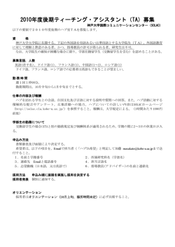
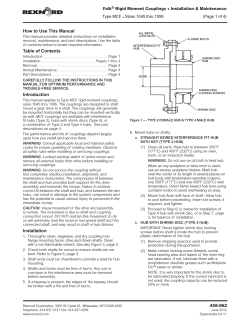
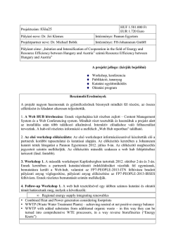
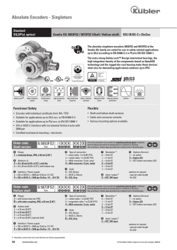
Falk™ Rigid Moment Couplings • Installation & Maintenance Type MCF • Sizes 2130 thru 2250 (Page 1 of 4) How to Use This Manual This manual provides detailed instructions on installation, removal, maintenance, and part descriptions. Use the table of contents below to locate required information. HEX SOCKET PIPE PLUG HEX HEAD CAP SCREW PREVAILING TORQUE LOCKNUT Table of Contents Introduction . . . . . . . . . . . . . . . . . . . . . . . . . . . . . . . . Page 1 Installation . . . . . . . . . . . . . . . . . . . . . . . . . . . Pages 1 thru 3 Removal . . . . . . . . . . . . . . . . . . . . . . . . . . . . . . . . . . Page 3 Annual Maintenance. . . . . . . . . . . . . . . . . . . . . . . . . . Page 4 Part Descriptions . . . . . . . . . . . . . . . . . . . . . . . . . . . . Page 4 CAREFULLY FOLLOW THE INSTRUCTIONS IN THIS MANUAL FOR OPTIMUM PERFORMANCE AND TROUBLE FREE SERVICE. Introduction This manual applies to Type MCF rigid moment couplings, Sizes 2130 thru 2250. The couplings are designed to shaft mount a gear drive to a shaft. The couplings will generally be mounted horizontally but they can be mounted vertically as well. MCF couplings are available with interference fit hubs with key (Type 2), keyless interference fit hubs with hydraulic removal (Type 6), or a combination of Type 2 and Type 6 hubs. See Figure 1. The performance and life of couplings depend largely upon how you install and service them. WARNING: Consult applicable local and national safety codes for proper guarding of rotating members. Observe all safety rules when installing or servicing couplings. WARNING: Lockout starting switch of prime mover and remove all external loads from drive before installing or servicing couplings. KEYLESS FIT HUB INTERFERENCE FIT HUB WITH KEY FIGURE 1 — TYPE 2 FEMALE HUB & TYPE 6 MALE HUB 5. If a key seat is present in the driven shaft, the edges of the key seat should be broken with a file and free of burrs. 6. Mount hubs on shafts a. Clean all parts. Heat hub to between 450°F (232°C) and 500°F (260°C) using an oven, torch, or an induction heater. WARNING: Do not use an oil bath to heat hub. When an oxy-acetylene or blow torch is used, use an excess acetylene mixture. Mark hub near the center of its length in several places on hub body with temperature sensitive crayons, one 450°F (232°C) and one 500°F (260°C) melt temperature. Direct flame toward hub bore using constant motion to avoid overheating an area. b. Mount hub flush with face of shaft. Allow hub to cool before proceeding. Refer to Figure 4. WARNING: Do not service the coupling without first completely reading installation, alignment, and maintenance instructions. The compressive fit between the shaft and hub provides both support for the drive assembly and transmits the torque. Failure to achieve correct fit between the shaft and hub, and between the two hubs can result in damage to the system components and has the potential to cause serious injury to personnel in the immediate vicinity. IMPORTANT CAREFULLY CLEAN SHAFT & HUB BORE & KEEP FREE OF ANY GREASE HUB DEGREASE FACE WARNING: Visual movement of the drive and assembly is normal. The movement is due to shaft and coupling connection runout. DO NOT restrain this movement; to do so will adversely load the reducer low speed shaft and the connected shaft, and may result in shaft or hub failures. Installation 1. Thoroughly clean, degrease, and dry coupling hub flange mounting faces, drive and driven shafts. Clean with a nonflammable solvent. See Figure 2. 2. Check both shafts for runout to ensure shafts are not bent. Refer to Figure 4. 3. Shaft ends must be chamfered to provide a lead for hub mounting. 4. Shafts and bores must be free of burrs. Any rust or corrosion in the interference area must be removed before assembly. Rexnord Industries, LLC, 5555 S. Moorland Rd., New Berlin, WI 53151-7953 Telephone: 262-796-4060 Fax: 262-796-4064 e-mail: [email protected] web: www.rexnord.com DRIVING AND DRIVEN SHAFTS FIGURE 2 458-864 January 2009 NEW Installation & Maintenance • Falk™ Rigid Moment Couplings (Page 2 of 4) Type MCF • Sizes 2130 thru 2250 TABLE 2 — Flange Fastener Tightening Torque SHAFT END FLUSH WITH FACE OF HUB SHAFT NOT FLUSH WITH END OF HUB INCORRECT CORRECT FIGURE 3 c. Check that the hub is correctly positioned on the shaft, then using dial indicators check hub runout as illustrated in Figure 4. Checking the hub runout ensures correctness of hub mounting and will reduce drive movement. Make sure runout values do not exceed limits listed in Table 1. If runout is excessive, remove hub following the removal instructions, and carefuly remount the hub to the shaft. INDICATOR #2 INDICATOR #1 INDICATOR #3 COUPLING SIZE Flange Fastener Size Grade 8 (Inch) 2130 MCF 2140 MCF 2150 MCF 2160 MCF 2170 MCF 2180 MCF 2190 MCF 2200 MCF 2210 MCF 2220 MCF 2230 MCF 2240 MCF 2250 MCF 0.875-9UNC x 3.75 0.875-9UNC x 4.00 1.000-8UNC x 5.00 1.000-8UNC x 5.50 1.000-8UNC x 5.50 1.000-8UNC x 6.00 1.125-7UNC x 6.50 1.125-7UNC x 6.50 1.250-7UNC x 7.50 1.250-7UNC x 8.00 1.500-6UNC x 8.50 1.500-6UNC x 9.00 1.500-6UNC x 9.50 Flange Fastener Tightening Torque Tolerance 5% (Nm) (lb-ft) 690 690 1085 1085 1085 1085 1480 1480 2135 2135 3660 3660 3660 510 510 800 800 800 800 1090 1090 1575 1575 2700 2700 2700 9. Fasten the torque arm to the bed frame per gear drive instructions and remove the lifting equipment. Rexnord recommends that a loose, unrestraining safety sling be attached to the bedplate and support structure, to support the drive in case of an emergency. 10. Using dial indicators per Figure 5, measure assembly runout on driving and driven shafts. Runout values should be within 0.005” (0.127mm) TIR (total indicator reading) to minimize drive movement. See Table 1. 11. Run the drive for a short period of time, and then shut off and lockout motor. Recheck all fasteners for specified torque. 12. The coupling installation is now complete. WARNING: Install the warning nameplate supplied with the coupling on the coupling guard or on some other support structure near the coupling. DIAL INDICATOR FIGURE 4 TABLE 1 — Maximum Runouts (TIR) for Dial Indicators - Inch (mm) All Sizes #1 .001 (0.025) #2 .003 (0.076) #3 .003 (0.076) 7. With suitable lifting equipment, move the drive/motor assembly into position approximately parallel and in line with the driven shaft using hub flanges as a guide. Align fastener holes, and install and hand tighten one flange fastener. Align hub registers and flange fastener holes. Install all flange bolts finger tight. 8. Use a precision torque wrench and equally tighten all opposing fasteners while allowing the drive assembly to move as required to draw the flanges together (flexible support). Continue tightening until flanges are mated and all flange fasteners are torqued to values specified in Table 2. 458-864 January 2009 NEW DIAL INDICATOR REVERSE DIAL INDICATOR METHOD FIGURE 5 Rexnord Industries, LLC, 5555 W. Moorland Rd., New Berlin, WI 53151-7953 Telephone: 262-796-4060 Fax: 262-796-4064 e-mail: [email protected] web: www.rexnord.com Falk™ Rigid Moment Couplings • Installation & Maintenance Type MCF • Sizes 2130 thru 2250 Coupling Disconnection WARNING: Do not disconnect torque arm or tie rod until the low speed coupling is completely disconnected. 1. With suitable equipment, remove the weight of the drive assembly from the coupling and driven shafts. It is necessary to make fine adjustments of position at each of the bedplate lugs. The lifting slings should have appropriate provisions for adjustment. 2. Lift the drive by the lifting lugs in the bedplate or wrap slings around the assembly when a bedplate is not used. Balance loads so drive is level and will not swing down when the coupling is disconnected. 3. Loosen flange fasteners in sequence until all fasteners have at least a 0.125” (3.175mm) clearance under the fastener heads. Remove all but one fastener near the top of the flange. Separate the two flanges using four 1/2–13UNC fasteners (not supplied with coupling) inserted in the four jackscrew holes in the male register flange. Continue backing off the last flange fastener as the flanges are separated. When completely separated, adjust the weight of the drive assembly until the weight is off the last fastener. Carefully remove the last fastener. 4. Adjust the drive assembly position until all the weight of the assembly is balanced. When the tie rod is no longer bearing any of the weight, disconnect the tie rod. Slowly lower the assembly to the ground. Hub Removal 1. Type 2 Hubs a. Thoroughly clean hubs of grease and solvents to avoid combustion when heat is applied. b. Assemble puller as shown in Figure 6. Check to make sure puller has enough stroke to pull the hub off. Be sure to adequately support both the hub and puller assembly using metal cable slings. Reference Table 3 for the hub puller bolt hole mounting pattern. c. Heat the hub evenly with a rosebud torch to approsimately 400° to 500°F (204° to 260°C) while applying pressure to the puller. The temperature may be measured with a heat sensitive crayon. Apply puller pressure until the hub clears the shaft. 2. Type 6 Hubs a. Mount a hydraulic hub puller (see Figure 7) on the end of the hub with a pressure rod against the shaft end. Reference Table 3 for the hub puller bolt hole mounting pattern. The puller must have an axial travel equal to or greater than the hub-to-shaft bore length. Be sure to adequately support both the hub and puller assembly using metal cable slings. b. Mount the hydraulic expansion fittings to the hub and high pressure hydraulic pump. Pressurize the hub-toshaft interface until oil is oozing out between bore and shaft, or to the removal pressure called out in Table 4. Apply axial removal force at the same time as pressurizing the hub. Shut off pressure (item 8 of Figure 7) prior to the groove being exposed beyond the shaft end. Rexnord Industries, LLC, 5555 S. Moorland Rd., New Berlin, WI 53151-7953 Telephone: 262-796-4060 Fax: 262-796-4064 e-mail: [email protected] web: www.rexnord.com (Page 3 of 4) TABLE 3 — Type 2 & Type 6 Hub Puller Bolt Holes COUPLING SIZE 2130 MCF 2140 MCF 2150 MCF 2160 MCF 2170 MCF 2180 MCF 2190 MCF 2200 MCF 2210 MCF 2220 MCF 2230 MCF 2240 MCF 2250 MCF Flange Face Puller Bolt Holes UNC Tap (2 x Dia Deep) BC - Inch (mm) UNC Tap (2 @ 180°) 5.50 (139.7) 6.25 (158.8) 7.00 (177.8) 8.00 (203.2) 9.00 (228.6) 10.00 (254.0) 11.00 (279.4) 12.00 (304.8) 12.50 (317.5) 14.00 (355.6) 15.50 (393.7) 17.00 (431.8) 18.00 (457.2) 0.375-16UNC 0.500-13UNC 0.500-13UNC 0.500-13UNC 0.625-11UNC 0.750-10UNC 0.750-10UNC 0.875-9UNC 0.875-9UNC 0.875-9UNC 1.000-8UNC 1.000-8UNC 1.125-7UNC TABLE 4 — Type 6 Hub Removal Pressure COUPLING SIZE 2130 MCF 2140 MCF 2150 MCF 2160 MCF 2170 MCF 2180 MCF 2190 MCF 2200 MCF 2210 MCF 2220 MCF 2230 MCF 2240 MCF 2250 MCF Maximum Recommended Pressure At Hub Bore When Dismounting Hub (MPa) (psi) 138 - 152 131 - 138 124 - 138 131 - 145 145 - 159 138 - 152 124 - 138 124 - 138 124 - 131 117 - 131 124 - 138 117 - 131 131 - 138 20,000 - 22,000 19,000 - 20,000 18,000 - 20,000 19,000 - 21,000 21,000 - 23,000 20,000 - 22,000 18,000 - 20,000 18,000 - 20,000 18,000 - 19,000 17,000 - 19,000 18,000 - 20,000 17,000 - 19,000 19,000 - 20,000 METAL CABLE SLINGS TO SUPPORT HUB AND PULLER HYDRAULIC CYLINDER TORCH ALLOY STEEL LATE SHAFT WITH OR WITHOUT ADJUSTING SCREW BAR STOCK COUPLING HUB TORCH GAUGE HAND PUMP OR HYDRAULIC PUMP FIGURE 6 — BASIC TYPE 2 HUB REMOVAL EQUIPMENT 458-864 January 2009 NEW Installation & Maintenance (Page 4 of 4) • Falk™ Rigid Moment Couplings Type MCF • Sizes 2130 thru 2250 Annual Maintenance COUPLING H SHAFT Whenever the equipment is down for general maintenance or service, recheck the tightening torque of flange fasteners. Tighten fasteners if necessary. For extreme or unusual operating conditions, check coupling more frequently. Part Descriptions Part descriptions are shown below. In addition, all coupling parts have identifying part numbers. When ordering parts, always SPECIFY SIZE and TYPE of hub, and part number. MCF COUPLING WITH A TYPE 6 MALE HUB & A TYPE 2 FEMALE HUB 3 6 1 LOW PRESSURE 2 PUMP VALVES 4 HIGH PRESSURE FIGURE 7 — BASIC TYPE 6 HUB REMOVAL EQUIPMENT (1) Hydraulic hub puller. This is a hydraulic ram that is threaded into the puller plate (9). (2) Low pressure pump. The pump should have a 5000 psi (34.5 MPa) maximum pressure rating. (3) Low pressure gage. The gage should have a large enough face for accurate readings, with a maximum pressure rating of psi 5000 psi (34.5 MPa). (4) Low pressure flex line and fittings. At 5000 psi (34.5 MPa), this line can be flexible, which makes it more convenient when hooking up the system. Appropriate end fittings and a gage mounting snubber are also needed. (5) High pressure pump. The pump should have a 40,000 psi (276 MPa) maximum pressure rating. (6) High pressure gage. The gage should have a large enough face for accurate readings, with a maximum pressure rating of 40,000 psi (276 MPa). (7) Rigid high pressure line and fittings. At 40,000 psi (276 MPa), a rigid steel, high pressure line with special high pressure connectors are mandatory. A high pressure tee and at least 2 high pressure elbows are needed to mount the gage and for routing the line. (8) High pressure valve. This valve is used to shut the pressure off at this end of the hub as it comes off the shaft. (9) Puller plate. This plate is threaded in the center to accept the hydraulic ram. It also has holes drilled in it to line up with the tapped puller holes in the hub. (See Table 3.) (10) Puller rods. These rods are usually threaded full length. They connect the hub to the puller plate. (Reference Table 3 for thread size.) (11) Nuts. These nuts position the puller plate. 458-864 January 2009 NEW 5 PART DESCRIPTIONS 1. Male Pilot Hub (Type 6) 2. Female Pilot Hub (Type 2) 3. Flange Bolt (Hex Head Cap Screw Grade 8) 4. Flange Nut (Locknut) 5. Hub Puller Bolt Holes 6. Socket Head Plug (BSP, not NPT) Rexnord Industries, LLC, 5555 W. Moorland Rd., New Berlin, WI 53151-7953 Telephone: 262-796-4060 Fax: 262-796-4064 e-mail: [email protected] web: www.rexnord.com
© Copyright 2026 Paperzz