Paper
zz
Explore Categories
Log in
Create new account
No category
Catalyst 2960-S and 2960-C Switches Command Reference, Cisco
Download
Report
Integrated Result System - Version 2015.01.07
Making Math Pretty – or How to Use LaTeX - Iowa State University
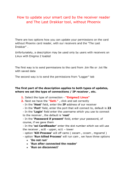
How to update your smart card by the receiver - The Last Drakkar
Download - Form
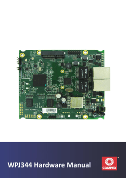
WPJ344 Hardware Manual - Compex
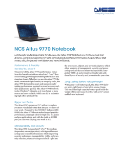
NCS Altus 9770 Notebook - NCS Technologies
Lab Manual of Basic Electrical Engineering LAB
Ultra Mobile FAQs
What If They Dont Speak English? - Macomb Intermediate School
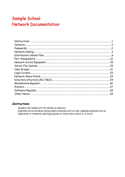
Sample School Network Documentation
© Copyright 2026 Paperzz
About Paperzz
DMCA / GDPR
Report