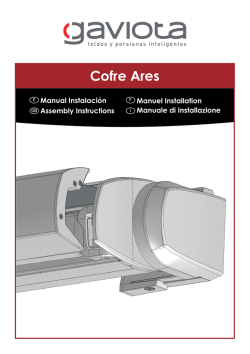
Cofre Iris
E
GB
Manual instalacion
Assembly instructions
F
I
Manuel installation
Manuale di installazione
Identificacion de piezas:
Parts identification:
E
GB
I
A
B
Soporte movil
E
E
GB Mobile support
F
I
Identification des pieces:
Identificazione dei pezzi:
F
Soporte fijo
GB fixed support
Support reglable
F
Support fixe
Supporto regolabile
I
Supporto fisso
B
B
1
2
A
E
GB
A
Soporte izquierdo
Left support set
F
I
3
E
GB
F
I
Soporte motor
Motor support
Support moteur
Supporto motore
Support gauche
Supporto sinistro
E
GB
4
E
GB
F
I
Soporte derecho
Right support set
5
Soporte punto
Round pivot support
Support cote oppose
Suporto con perno tondo
2
E
GB
F
I
Soporte máquina
Gear support
Support treuil
Supporto argano
F
I
Support droit
Supporto destro
6
E
GB
F
I
Soportes pared
Wall supports
Support a mur
Supporto parete
E
GB
7
F
I
E
GB
F
I
Perfil barra de carga
Frontal profile
Profil barre de charge
Profilo frontale
E
GB
F
I
Incluye ademas bolsa con kit
de regletas
It also includes a bag with set
of adjustament
Avec un kit de reglettes inclu
Include anche un kit di
accessori
E
GB
F
I
Bolsa Nº1: Tornillería
Bolsa Nº2: Piezas de plástico
Bag Nº1: Screws
Bag Nº2: Plastic pieces
Sachet n.1: Visserie
Sachet n.2: Pièces en plastique
Sacchetto Nº1: viteria
Sacchetto Nº2: tappini in plastica
3
Perfil cajon
Box profile
Profil caisson
Profilo cassonetto
E
GB
E
Pasos para el montaje:
Assembly instructions:
F
I
Pas a suivre pour le montage:
Istruzioni di montaggio:
Lineas mínimas (m)
GB Minimum width (m)
F
Largeurs minimales (m)
I
Larghezza minima (m)
Tamaño brazo smart (m)
Smart arm, arms projection (m)
Longueur bras smart (m)
Sporgenza braccio smart
Línea mínima con máquina o
motor por fuera (m)
Minimum width with gear or
motor outside (m)
Largeur minimale avec treuil ou
moteur a l´exterieur (m)
Larghezza minima con argano
o con motore esterno al
supporto (m)
Línea mínima con motor por
dentro (m)
Minimum width with motor
inside (m)
Largeur minimale avec moteur
a l´interieur (m)
Larghezza minima con motore
interno al supporto (m)
1.00
1.26
1.22
E
GB
F
I
1.25
1.51
1.47
1.50
1.76
1.73
1.75
2.02
1.98
2.00
2.35
2.31
2.25
2.60
2.56
2.50
2.85
2.81
Máquina o motor por fuera
With gear or motor outside
Treuil ou moteur a l´exterieur
Con argano o motore esterno
E
GB
F
I
4
Motor por dentro
With motor inside
Moteur a l´interieur
Motore interno
E
Paso 1: Cortar perfiles (los dos a la misma
medida) y eje. Enrollar la lona centrada en el
eje. El borde de la lona debe quedar a 5mm. del
borde del eje en el lado del punto.
GB
Step 1: Cut the profi les (the two of them with the
same measure) and the tube. Roll up the fabric
staying centered at the tube. The fabric edge
must be 5mm. from the tube edge at the pivot
side.
F
1: Couper les profils (les 2 à la même mesure) et
l´axe. Enrouler la toile centrée sur l´axe. Le bord
de la toile doit rester à 5mm du bord de l´axe du
côté opposé au treuil.
I
Fase 1: Tagliare i profili ( 2 di essi con la stessa
misura) e il tubo. Arrotolare il tessuto in posizione
centrale rispetto al rullo. L’orlo del tessuto deve
essere 5mm lontano dall’orlo del tubo al lato del
perno.
E
Tabla de descuentos Iris
F
GB Cutting adjustament for Iris box
I
Tableau mesures de coupe
Tabella riferimento per casstonetto iris
Longitudes de corte (mm)
Cutting adjustments (mm)
Longueurs de coupe (mm)
Riferimento x i tagli (mm)
Con máquina
With gear
Avec treuil
Con argano
Con motor por fuera
With motor outside
Avec moteur a
l´exterieur
Con motore esterno
Con motor por dentro
With motor inside
Avec moteur a
l´interieur
Con motore interno
Perfiles (cajón y barra de carga)
Profiles (box and frontal profile)
Profils (caisson et barre de charge)
Profili (cassonetto e barra frontale)
L-166
L-166
L-130
Eje ø 70 • Ø 70 tube
Axe ø 70 • Rullo Ø70
L-167
L-H-102
L-H-104
Lona • Fabric
Toile • Tessuto
L-176
L-176
L-140
Felpudo • Elastic strap
Joint brosse • Banda elastica
L-166
L-166
L-130
Perfil tapa ojiva faldilla
Valance ogive cover profile
Profil frontal caisson rainure
Profilo ogiva copertura cassonetto
L-166
L-166
L-130
5
E
GB
F
I
Paso 2: Meter el eje con lona y casquillos dentro
del perfi l cajón. Meter también el felpudo en el
perfi l cajón cortando el felpudo sobrante.
Step 2: Introduce the tube with fabric and caps
inside the box profi le. Put also the elastic strap in
thebox profi le and cut the leftovers.
2: Introduire l´axe avec la toile et les embouts
dans le profil caisson. Mettre aussi le joint brosse
et couper le restant. Introduire latéralement.
Fase 2: Introdurre il tubo con il tessuto e le
calotte dentro al profilo cassonetto. Inserire
anche la banda elastica nel profilo cassonetto e
tagliare l’avanzo. Introdurre lateralmente.
E
Paso 3: Atornillar soportes móviles al perfi l cofre.
GB
Step 3: Screw down the arm supports to the
mobile box profi les.
3: Visser les supports réglables au profil coffre.
F
I
Fase 3: Avvitare i supporti mobili ai profili del
cassonetto.
E
Paso 4: Seleccionar ranura según el ángulo que
se desee, dentro del siguiente rango:
•A pared: ranuras 1 y 2.
•A techo: ranuras 3 y 4.
Montar según versión (los pasos son los mismos
sea cual sea la ranura elegida).
Step 4: Choose the groove according to the
desired angle, always in between the following
range:
•Wall option: grooves 1 and 2.
•Ceiling option: grooves 3 and 4.
Install depending the option (the steps are the
same regardless of the chosen groove).
4: Sélectionner la rainure en fonction de
l´inclinaison désirée, dans le marge suivant:
•A mur: rainures 1 et 2.
•A toit: rainures 3 et 4.
Réaliser le montage désiré (les pas à suivre
sont les mêmes indépendamment de la rainure
choisie)
GB
F
Se mete por el lado • Introduce laterally
Mètre sur le côté • Metro sul lato
Ranuras • Grooves
Rainure • Posizioni
Fase 4: Selezionare
la scalanatura relative
all’angolazione desiderata, sempre tra I seguenti
range:
•A parete: Scanalatura 1 e 2.
•A Tetto: Scanalatura 3 e 4.
Montar según versión (los pasos son los mismos
sea cual sea la ranura elegida).
Pared • Wall
Mur • Parete
E
GB
F
I
Techo • Ceiling
Toit • Tetto
Posibilidades:
Options:
Possibilités
Possibilità
6
I
E
GB
Versión máquina:
Gear version:
F
I
E
a).Colocar por este orden en el extremo punto
del eje:
1. Soporte fijo.
2. Bócola punto.
3. Soporte punto.
Colocar los tornillos M6 para sujetar las
piezas al soporte móvil. No apretar.
b).Colocar por este orden en el extremo máquina
del eje:
1. Soporte fijo.
2. Bócola cuadrada.
3. Soporte punto.
Colocar con los tornillos M6 para sujetar las
piezas al soporte móvil. No apretar.
Atornillar la máquina en su soporte y
posteriormente al soporte móvil.
GB
a).Place the pieces in the round pivot side of the
tube following this order:
1. Fixed support.
2. Plastic bearing for round pivot.
3. Round pivot support.
Put the M6 screws for fi xing the pieces to
the mobile support. Do not tighten.
b).Place the pieces in the gear side of the tube
following this order:
1. Fixed support.
2. Plastic bearing for squared pivot.
3. Round pivot support.
Put the M6 screws for fi xing the pieces to
the mobile support. Do no tighten.
Screw down the gear at its support and later
to the mobile support.
F
a).Placer dans l´ordre suivant à l´extrémité
côté opposé de l´axe:
1. Support fixe.
2. Boucle côté opposé.
3. Support côté opposé.
Placer les vis M6 pour fixer les pièces
support réglable. Ne pas serrer.
b).Placer dans l´ordre suivant à l´extrémité
côté treuil de l´axe:
1. Support fixe.
2. Boucle carrée.
3. Support côté opposé.
Placer les vis M6 pour fixer les pièces
support réglable. Ne pas serrer.
Visser le treuil à son support et après
support réglable.
Option treuil:
Versione argano:
a).Porre i pezzi in questo ordine nell’estremo
perno del rullo:
1. Supporto fisso.
2. Di plastica x perno rotondo.
3. Supporto perno rotondo.
Porre le viti M6 x il fissaggio dei pezzi al
supporto mobile. Non stringere.
b).Porre i pezzi in questo ordine nell’estremo
perno del rullo:
1. Supporto fisso.
2. Boccola quadrata
3. Supporto perno rotondo
Porre le viti M6 x il fissaggio dei pezzi al
supporto mobile. Non stringere.
Avvitare l’argano al proprio supporto e dopo
al supporto mobile.
Techo-Der: Techo Derecha • Ceiling Right
Toit Droit • Soffitto Destro
Techo-Izq: Techo Izquierda • Ceiling Left
Toit Gauche • Soffitto Sinistro
Pared-Der: Pared Derecha • Wall Right
Mur Droit • Parete Destra
Pared-Izd: Pared Izquierda • Wall Left
Mur Gauche • Parete Sinistra
du
au
du
au
au
7
I
E
GB
Versión motor por fuera:
Motor version on the outside:
F
I
Option moteur a l´exterieur:
Versione motore x esterno:
a).En el extremo motor, atornillar el motor al
soporte motor, ensamblar el soporte fi jo
(extremo del cofre que llevará el motor), con
el soporte móvil y fi nalmente, introducir el
conjunto soporte/motor en el eje. Con los
tornillos M6, atornillar los tres soportes.
a).Au côté moteur, visser le moteur au support
moteur, assembler le support fixe (extrémité
du coffre qui portera le moteur), avec le
support réglable et finalement, introduire
l´ensemble support/moteur dans l´axe. Avec
les vis M6, visser les trois supports.
F
a).At the motor side, screw down the motor
to the motor support, assemble the fi xed
support (box side that will incorporate the
motor) with the mobile support and fi nally,
introduce the motor/support set into the tube.
Tighten then the three supports with the M6
screws.
a).Al lato motore, avvitare al supporto motore,
assemblare il supporto fissato (lato cassonetto
che incorporerà il motore) con l’appoggio
mobile e successivamente introdurre il
supporto motore nel tubo. Stringere poi i tre
appoggi con le viti M6.
I
E
b).En el extremo punto, colocar por este orden:
1. Soporte fijo.
2. Bócola punto.
3. Soporte punto.
Colocar los tornillos M6 para sujetar las
piezas al soporte móvil. No apretar.
b).Au côté opposé, placer dans l´ordre suivant:
1. Support fixe.
2. Boucle pour côté opposé.
3. Support côté opposé.
Placer les vis M6 pour fixer les pièces au
support réglable. Ne pas serrer.
F
GB
b).Place the parts in the round pivot side of the
tube following this order:
1. Fixed support.
2. Plastic bearing for round pivot.
3. Motor/round pivot support.
Put the M6 screws for fi xing the pieces to
the mobile support. Do not tighten.
b).Porre l pezzi in questo ordine, nel lato perno
rotondo.
1. Supporto fisso.
2. Plastica per perno rotondo.
3. Supporto Perno rotondo motore.
Porre le viti M6 x il fissaggio dei pezzi al
supporto mobile. Non stringere.
I
E
GB
8
E
GB
Versión motor por dentro1:
Motor version inside1:
F
I
Option moteur a l´interieur1:
Versione motore interno1:
E
a).En el extremo motor, atornillar el motor al
soporte punto, ensamblar el soporte fijo
(extremo del cofre que llevará el motor), con
el soporte móvil y finalmente, introducir el
conjunto soporte/motor en el eje. Con los
tornillos M6, atornillar los tres soportes.
a).Au côté moteur, visser le moteur au support
côté opposé, assembler le support fixe
(extrémité du coffre qui portera le moteur),
avec le support réglable et finalement,
introduire l´ensemble support/moteur dans
l´axe. Visser les 3 supports avec les vis M6.
F
GB
a).At the motor side, screw down the motor to
the round pivot support, assemble the fixed
support (box side that will incorporate the
motor) with the mobile support and fi nally,
introduce the motor/support set into the tube.
Tighten then the three supports with the M6
screws.
a).Al lato motore, avvitare al supporto motore,
assemblare il supporto fissato (lato cassonetto
che incorporerà il motore) con l’appoggio
mobile e successivamente introdurre il
supporto motore nel tubo. Stringere poi i tre
appoggi con le viti M6.
I
E
b).En el extremo punto, colocar por este orden:
1. Soporte fijo.
2. Bócola punto.
3. Soporte punto.
Colocar los tornillos M6 para sujetar las
piezas al soporte móvil. No apretar.
b).Au côté opposé, placer dans l´ordre suivant:
1. Support fixe.
2. Boucle côté opposé.
3. support côté opposé.
Placer les vis M6 pour fixer les pièces au
support réglable. Ne pas serrer.
F
GB
b).Place the parts in the round pivot side of the
tube following this order:
1. Fixed support.
2. Plastic bearing for round pivot.
3. Round pivot support.
Put the M6 screws for fi xing the pieces tothe
mobile support. Do not tighten.
b).Porre l pezzi in questo ordine, nel lato perno
rotondo:
1. Supporto fisso.
2. Plastica per perno rotondo.
3. Supporto Perno rotondo motore.
Porre le viti M6 x il fissaggio dei pezzi al
supporto mobile. Non stringere.
I
Esta confi guración no se recomienda para montaje con motores
Gaviota Simbac Argos o similares.
1
Cette option n´est pas recommandée pour montage avec
moteurs Gaviota Simbac Argos ou similaires.
F
This option is not recommended for Argos Gaviota Simbac
motors or similar.
1
Questa opzione non viene raccomandata per i motori Gaviota
Simbac Argos e loro similari.
I
E
1
GB
1
9
E
Paso 5: Ensamblar los brazos invisibles Smart.
Montar los brazos en su alojamiento, introducir
los ejes macizos y fijar los mismos con los
prisioneros inferiores. Montar las regletas a los
terminales delanteros.
GB
Step 5: Assemble the Smart lateral arms.
Fit the arms at their place, introduce the solid
axles and fix them with the lower hexagonal
socket set screws.
F
5: Assembler les bras invisibles Smart. Monter
les bras à sa place, introduire les axes massifs et
fixer-les à l´aide des écrous prisonniers. Placer les
réglettes aux profils frontaux.
I
Fase 5: Assemblare i bracci laterali Smart.
Montare i bracci, sulla forcella, introdurre il perno
in acciaio e fissarlo con la vite a brugola posta
sulla forcella inferiore.
E
Paso 6: Insertar la lona en el perfi l barra de carga
y atornillar la regletas a ésta. Insertar la faldilla si
está prevista. Montar las tapas del perfil. Quitar
las fundas protectoras de los brazos. Ajustar
lateralmente las regletas para que ambos brazos
se plieguen correctamente al cerrar. Ver en la
tabla adjunta los valores orientativos para la
colocación lateral de las regletas.
6: Introduire la toile dans le profil barre de charge
et y visser les réglettes. Insérer le lambrequin
si c´est prevu. Poser les couvercles du profil.
Enlever les protections en plastique des bras.
Ajuster latéralement les réglettes pour que les
deux bras se plient correctement au moment
de la fermeture. Voir sur le tableau ci-joint les
valeurs orientatives pour le placement latéral des
réglettes.
F
GB
Step 6: Introduce the fabric in the frontal profile
and screw down the adjustments to it. Insert
the valance if planned. Place the profile caps.
Remove the security covers from the arms.
Regulate laterally the adjustments so both arms
can properly fold when closing the awning. See
the attached table with the measures for laterally
placing the adjustments (only for guidance).
Fase 6: Introdurre il tessuto nel profilo frontale
e avvitarlo ad esso. Inserire ..... se programmata.
Porre i tappi del profilo. Rimuovere le coperture
di sicurezza dai bracci. Regolare lateralmente
le regolazioni cosi’ le braccia si piegheranno
correttamente alla loro chiusura. Vedere la tabella
allegata con le misure for porre correttamente le
regolazione.
I
10
Orientación para la colocación de las
regletas:
F
Orientation pour le placement des
reglettes:
GB Position for placing the adjustments:
I
Posizione per porre le regolazioni:
E
E
Regular en altura las regletas para que el cofre
cierre perfetamente. Poner los tapones en las
regletas.
GB
Regulate the height of the adjustments in order
to secure the closing of the box. Place the caps
into the adjustments.
F
Medida de brazos (m)
Arms projection (m)
Mesures des bras (m)
Proiezione della braccia
Distancia a (mm)
“A” distance (mm)
Distance “a”
Distanza “a” (mm)
1.00
1.25
1.50
Régler l´hauteur des réglettes pour que le coffre
ferme parfaitement.
12
1.75
2.00
I
Regolare l’altezza delle regolazioni in maniera da
rendere sicura la chiusura del cassonetto. Porre le
calotte nella regolazioni.
2.25
87
2.50
E
Paso 7: Colocar los soportes pared en el muro.
Atención: ver las medidas de colocación de
los soportes pared en la tabla de descuentos
antes de taladrar la pared.
Las caras exteriores de los mismos deben de
quedar enrasadas con las caras exteriores de
los soportes fijos (+/- 6mm) cuando se cuelgue
el cofre. Si sobresale la cara del soporte pared
fuera del soporte fijo, habrá de cortar la tapa
de plástico. Se recomienda
utilizar 4 tornillos por cada
soporte pared.
7: Fixer les supports au mur.
Attention: vérifier les mesures de placement
des supports à mur sur le tableau ci-joint avant
de percer le mur.
La partie externe des supports à mur doit rester
au ras de la partie externe des supports fixes
(+/- 6mm) au moment de suspendre le coffre. Si
la partie externe du support à mur dépasse celle
du support fixe, il faudra couper le couvercle
en
plastique.
On
recommande d´utiliser 4
vis pour chaque support
à
mur.
F
GB
Step 7: Place the
supports at the wall.
Attention: check the
support
placement
measures at the cutting
adjustments chart before drilling the wall.
The exterior sides of both supports must be
facing the exterior sides of the fixed supports
(+/- 6mm.) whenever the box is being hanged.
The plastic cap will have to be partially removed,
in case the side of the wall support exceedes the
side of the fixed support. We recommend using
4 screws per each wall support.
Fase 7: Collocare i
supporti al muro.
Attenzione: controlla
le misure di posa dei
supporti nella tabella
dei taglio prima di trapanare il muro. I lati di
entrambi I supporti devono rimanere ai lati esterni
dei supporti esterni (+/- 6mm) ogni qualvolta
il cassonetto risulti appeso. Se agganciando il
cassonetto, sbordasse dal supporto fissato a
parete, si consiglia rifilare il tappo in plastica di
chiusura. Si raccomanda di utilizzare 4 viti per
ogni sopporto.
I
11
E
En montaje a techo, dejar suficiente espacio
hasta la pared para la llave de regulación.
GB
In ceiling option, let enough space before the
wall for being able to operate the adjustment
tool.
F
Pour le montage à toit, laisser un espace suffisant
jusqu´au mur pour permettre l´utilisation de la clé
de réglage.
I
Nel montaggio a soffitto, lasciate abbastanza
spazio
fino
alla
parete
per
operare
successivamente con lo stumento di regolazione.
E
Paso 8: Colgar el cofre en los soportes pared.
GB
Step 8: Place the box in the wall supports.
E
Paso 9: Atornillar las dos placas que limitan los
desplazamientos (vertical y horizontal).
GB
Step 9: Screw down the two brackets that control
the movement (vertical & horizontal).
F
9: Visser les deux plaques qui limitent les
déplacements (vertical et horizontal).
I
Fase 9: Avvitare le 2 placche che limitano
movimenti (verticali e orizzontale).
E
Paso 10: Regular la inclinación del cofre
y después, apreetar los dos soportes fijos
(tornillos M6).
GB
Step 10: Adjust the box inclination, tightening
then the two fixed supports (M6 screws).
F
10: Régler l´inclinaison du coffre et après, visser
les deux supports fixes (vis M6).
I
Fase 10: Regolare l’inclinazione del casssonetto,
stringendo poi i 2 supporti fissati. (viti M6).
i
12
8: Suspendre le coffre en l´accrochant aux
supports à mur.
F
Fase 8: Collocare il cassonetto nei supporti pareti.
I
E
Paso 11: Actuar en la regulación de altura del
codo para que cierre perfectamente el cofre
(antes de regular en caso de estar usando
máquina, sujetar los brazos con su funda y soltar
lona accionando la máquina).
GB
Step 11: Adjust the elbow’s height in order to
have a perfect closing of the box (in case a gear
it is being used and before any adjustment, hold
the arms with their security covers and roll down
the fabric by using the gear).
F
11: Régler l´hauteur du coude du bras pour une
fermeture parfaite du coffre (pour le montage à
treuil, avant de faire le réglage garder les bras
avec leur protection en plastique et lâcher de la
toile en actionnant le treuil).
I
Fase 11: Regolare l’altezza per poter chiudere
perfettamente il cassonetto (prima di regolare
nel caso stiate usando un argano, tenere le
braccia con il loro tappo di sicurezza e srotolare
il tessuto).
E
Paso 12: Colocar a presión las tapas del cajón.
Montar las tapas del cajón según la opción de
accionamiento escogida:
a).Una tapa baja y una tapa alta (máquina
o motor por fuera). Abrir la salida para el
cáncamo en caso de necesidad.
b).Dos tapas bajas (motor por dentro).
Insertar el perfil tapa ogiva faldón (Cod. 80130328,
Blanco ó 80130329, Negro), en caso de no haber
montado faldilla en la barra de carga.
12: Placer à pression les couvercles du coffre.
Placer-les selon l´option de manoeuvre choisie:
a).Un couvercle en bas et un couvercle en
haut. (pour treuil ou moteur à l´extérieur).
Ouvrir la sortie pour l´anneau si c´est
nécessaire
Deux couvercles en bas (moteur à l´intérieur).
Introduire le profil frontal rainuré (Code
80130328, Blanc ou 80130329, Noir), si on n’a
pas accroché de lambrequin à la barre de charge.
F
GB
Step 12: Press and place the box caps. Assemble
the caps depending on the chosen option:
a).One low cap and one high cap (gear or
motor outside). Leave some space for the
gear eye in case it were necessary.
b).Two low caps (motor inside).
Introduce the valance ogive cover profile
(Code 80130328, White or 80130329, Black) in
case the valance had not been installed at the
charge bar.
Fase 12: Premere e porre i tappi cassonetto.
Assemblare i tappi scegliendo tra le seguenti
opzioni:
a).Un tappo in alto e uno in alto (argano
o motore x esterno). Lasciare spazio se
necessario x l’occhiolo dell’argano.
b).Due tappi inferiori (motore interno).
Introdurre Profilo di chiusura ogiva (codice
80130328,
Bianco
ó
80130329, Nero) nel
caso non abbiate
montato
la
barra.
I
13
E
Paso 13: Detalle de la extracción del eje, en caso
de desmontaje de los brazos.
GB
Step 13: Tube removal detail in the event of
taking apart the arms.
F
13: Détail de l´enlèvement de l´axe, en cas de
démontage des bras.
I
Fase 13: Dettaglio dell’estrazione del rullo, nel
caso di smontaggio dei bracci.
E
Paso 14: En caso de desmontar el motor: sujetar
los brazos con su funda (abrir primero el cofre
lo necesario) y retirar los tornillos que sujetan el
motor. Retirar después tres de los tornillos del
soporte del motor, dejando uno sólo a modo de
seguridad, quedándose éste un poco suelto para
que se pueda girar el soporte tanto como sea
necesario para que se pueda sacar el motor.
14: En cas du démontage du moteur: soutenir
les bras avec leur protection en plastique (ouvrir
premièrement le coffre tout le nécessaire) et
enlever les vis qui fixent le moteur. Enlever après
trois des vis du support moteur, laissant une
seule pour sécurité, restant celui-ci légèrement
dévissé afin de pouvoir faire pivoter le support le
nécessaire jusqu`à permettre d´enlever le moteur.
F
GB
Step 14: In case the motor has to be removed:
hold the arms with their security covers (opening
first the box as needed) and take away the screws
that are fixing the motor. Remove then three
screws of the motor support and leave one for
safety reasons. Thus, the one remaining has to be
not tighten in order to allow turning the support
as needed for taking out the motor.
Fase 14: Nel caso il motore debba essere
rimosso: tenere ferme le braccia con la loro
chiusura di sicurezza (aprendo prima il cassonetto
se necessario) . Rimuovere poi le 3 viti dal
supporto motore e lasciarne uno per ragioni
di sicurezza. Quello rimasto non deve essere
stretto in maniera da permettere il giramento dei
supporti se c’è bisogno di tirare fuori il motore.
I
14
E
NOTAS:
Elementos recomendados para los ejes de la lona:
•Eje ø70x1 ojiva.
•Casquillo ø70 ojiva espiga redonda: cod. 80020039.
•Casquillo ø70 ojiva transmisión espiga cuadrada: cod. 80020037.
•Adaptador motor: cod. 60070059.
*Sistema compatible con:
•Máquinas Gel 1:11 Pasante Cáncamo 120 mm.
•Motores tipo cofre Gaviota Simbac. Serie 45.
GB
NOTES:
Recommended caps for the fabric tubes:
•Ø70x1 tube with ogive.
•Ø70 ogive round cap with round pivot: cod. 80020039.
•Ø70 ogive driving round cap with square pivot: cod. 80020037.
•Motor adaptor : cod. 60070059.
Compatible system with:
•Gel gear 1:11, 120 mm. Eye, Long Screw.
•Gaviota Simbac motors for awning boxes. 45 Series.
F
NOTE:
Eléments recommandés pour les axes de toile:
•Axe a gorge ø70x1.
•Embout mâle ø70 côté opposé sortie ronde: code 80020039.
•Embout mâle ø70 côté manoeuvre sortie carrée : code 80020037.
•Adapteur moteur: cod. 60070059.
*Système compatible avec:
•Treuil Gel 1:11 Anneau 120 mm.
•Moteurs type coffre Gaviota Simbac. Série 45.
I
NOTE:
Elementi raccomandati x il rullo del tessuto:
•Rullo Ø70x1 Ogiva.
•Calotta ogiva Ø70 Rotonda: Cod 80020039.
•Calotta Ø70 Ogiva Trasmissione quadrato: Cod. 80020037.
•Adattatore x motore: Cod. 60070059.
*Sistema compatibile con:
•Arganello Gel 1:11.
•Motore x cassonetto tipo Gaviota Simbac Serie 45.
15
Autovía de Alicante, A-31 Km.196
03630 Sax (Alicante) - España / Spain
Tel. +34 965 474 200 • Fax +34 965 475 680
International Dept: +34 966 968 276 • Fax +34 966 968 075
[email protected] - [email protected]
www.gaviotasimbac.com
REF. 4004-404 • GAVIOTA SIMBAC, S.L. • NOVIEMBRE 2014 © COPYRIGHT RESERVED
GAVIOTA SIMBAC, S.L.
© Copyright 2026 Paperzz