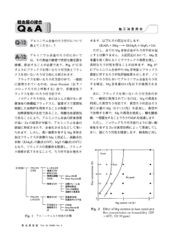
1
内容
1.実海域シミュレーション
・波浪中の船体運動計算(プロペラ影響あり・なし)
2.各種省エネデバイスの最適化
・SBDシステムの構築+形状最適化
3.実船スケールの船尾流れ計算
・舵直圧力の尺度影響
4.実プロペラ計算
・プロペラ単独性能試験
・自航試験
5.Tokyo2015(CFDWS)
・新船型/テストケース
平成26年度(第14回)海上技術安全研究所研究発表会
2
波浪中計算(プロペラ影響あり・なし)
対象船型
:KVLCC2船型
格子点数
:約820万点
レイノルズ数:2.55e6
フルード数 :0.142
向波規則波中:
(吸収造波方法)
λ/L=0.6, 1.1, 1.6
Hw/L=0.01875
2自由度運動計算
(ピッチ、ヒーブ)
プロペラ影響あり:
平水中モデルポイント
(簡易プロペラ理論)
乱流モデル:EASM
平成26年度(第14回)海上技術安全研究所研究発表会
3
波浪場計算(λ/L=1.1、ΔZ=0.002)
平成26年度(第14回)海上技術安全研究所研究発表会
4
波浪中の船体運動(プロペラ影響なし、λ/L=1.1)
平成26年度(第14回)海上技術安全研究所研究発表会
5
波浪中計算(プロペラ影響なし)
左上:ヒーブ
右上:ピッチ
下 :抵抗増加
平成26年度(第14回)海上技術安全研究所研究発表会
6
波浪中計算(プロペラ影響あり、λ/L=0.6)
t/Te = 0
t/Te = 1/4
t/Te = 1/2
t/Te = 3/4
Total velocity distribution
平成26年度(第14回)海上技術安全研究所研究発表会
Averaged total velocity
Wave height and motions
7
波浪中計算(プロペラ影響あり、λ/L=1.1)
t/Te = 0
t/Te = 1/4
t/Te = 1/2
t/Te = 3/4
Total velocity distribution
平成26年度(第14回)海上技術安全研究所研究発表会
Averaged total velocity
Wave height and motions
8
GT-Parts
(Message Passing
(HULLDES
OOInterface)
(Successive Quadratic Programming: SQP)
(Fig.3 RaNSFig.4
(7)
Fj
0
j
(
RaNS
CFD
)8)
(HULLDES
OO
CFD
重合格子技術と非線形最適化理論の導入による
)
)
CFD援用最適省エネルギーデバイス設計法
(7)
g
F
0
)
CFD
(
2
ij
2
i
j
)
j
i
2
g ij
2
j
(x,y,z)
j
, , ) (j=1,2,3)
1
2
Ggen. / Pwise.
HullDes
2
i
Fj
j InHouse GG. j
0Grid
Grid
InHouse GG.
j
F G-TOOL
(
(x,y,z)
, , ) (j=1,2,3)
2
3
Grid
Grid
Grid
Cooperation
with External
Applications
G-TOOL
SUGGAR++
Interpolation
Information
NAGISA
Grid
Grid
Grid
Grid
Grid
Grid
Grid
Grid
Interpolation
Grid
Grid
Grid
Grid Grid
Information
Cooperation
with External
Applications
SUGGAR++
Grid
Grid
Grid
NAGISA
Grid
Grid
Grid
Coop.
with External Apps. InHouse GG.
HullDes
Ggen. / Pwise.
SURF V.7
OPENFOAM
Fig.1 Interface between GT.V1 and outer components:
Coop. with External Apps.
meshing / CFD / other software tools
NAGISA
Structured / Unstructured MultiInterpolation
Block Grids / Interpolation
Information
Information
SURF V.7
OPENFOAM
Fig.1 Interface between GT.V1 and outer components:
meshing
/ CFDof/ other
software tools SUGGAR++
Three layer
structure
G-TOOL
Structured / Unstructured MultiBlock Grids
Fig.3 Comparison of serial and parallel computation
OPT
Interface with MPImethod
Parallel Coding
architectures
for SQP
algorithm:
rows,
serial architecture,
and
Overview
of the
present
automatic optimization
Grid/ Interp.
CFD
Information
parallel
respectively
basedarchitecture,
on MPI parallel
coding architecture
GM
GT.V1CFD
and outer components:
P3D / 3D
G-TOOL
meshing / CFD / other software tools
Assembly
P3D / 3D
SUGGAR++
G-TOOL
Assembly
G-Tool Overset
Grid/
Interp. Layer
Information
Information
CFD
P3D
/ 2D
HullDes
Ggen. / Pwise.
G-Tool Assembly InHouse
Layer GG. G-Tool Overset
G-TOOL
Information Layer
Overset
AE
OPT
G-Tool Basic
Geometry Layer
G-TOOL
Parts
CAD
GM
P3D / Wireframe
Surface
Geometry
Information
Information
CAD
P3D / 3D
P3D / 2D
G-TOOL
Parts
G-Tool Basic G-Tool Assembly Layer
G-TOOL
Geometry Layer
Assembly
G-Tool Basic
Geometry Layer
G-TOOL
P3D / Wireframe
Surface
Parts
Geometry
P3D / 2D
Information Information
HullDes
Fig.2 GT.V1
layer structure
Geometry
Ggen. / three
Pwise.
InHouse GG.
GTV.1-CFD 2
GTV.1-CFD n
GTV.1-CFD 2
1 present automatic optimization method
Fig.4 GTV.1-CFD
Overview of the
based on MPI parallel coding architecture (AE - Asynchronous
GTV.1-CFD
parallel
evaluator,2 GM - Geometry modeler, and OPT –
GTV.1-CFD n
Optimizer)
3.
Grid
Grid
Grid
HullDes
Ggen. / Pwise.
InHouse GG.
GTV.1-CFD 1
Interface with MPI Parallel Coding
AE
Fig.2 GT.V1 three layer structure
Grid
Grid
Grid
GTV.1-CFD 1
G-Tool Assembly Layer
GM
Grid
Grid
Grid
Structured / Unstructured MultiG-TOOL
Block
Grids / Interpolation
Overset Information
AE
Fig.3 Comparison of serial and parallel computation
architectures
OPT for SQP algorithm: rows, serial architecture, and
Interface
with MPI CAD
Parallel
Coding
parallel
architecture,
respectively
G-Tool Overset
Information Layer
G-TOOL
Overset
Structured / Unstructured MultiFig.1 Interface
Grid/ Interp.between
Block Grids / Interpolation
Information Information
SUGGAR++
Fig.3 Comparison of serial and parallel computation
architectures for SQP algorithm: rows, serial architecture, and
parallel architecture, respectively
Structured / Unstructured MultiBlock Grids
OPENFOAM
Grid
Grid
Grid
Grid
Grid
Grid
Interpolation
Information
G-TOOL
SURF V.7
Interpolation
Information
Structured / Unstructured MultiBlock Grids
SUGGAR++
Coop. with External Apps.
Interpolation
Information
Grid
Grid
Grid
Grid
Grid
Grid
Grid
Grid
(7)
Grid
Cooperation
with External
Applications
1
(Asynchronous)
Master-Slave
Comparison of serial and parallel computation
(
RaNS
CFD
architectures
for SQP algorithm:
)
(Left) serial
architecture, (right) parallel architecture
OOHullDes
)
g ij
Master-Slave
(Synchronous)
(x,y,z)
Fj (
Interface between G-TOOL and outer components:
1 2 3
(HULLDES
Ggen. / Pwise.
, , ) (j=1,2,3)
meshing
/ CFD / other software tools
GT-Parts
2
Fj (
9)
3
CFD
Information
P3D / Wireframe Surface
Information
3
Fig.2 GT.V1 three layer
structure
GT-Assembly
3.
平成26年度(第14回)海上技術安全研究所研究発表会
CFD
CFD
GTV.1-CFD n4.
Fig.4 Overview of the present automatic optimization
AE - method
Asynchronous parallel evaluator
GT.V1
Fig.5
based on MPI parallel coding architecture (AE - Asynchronous
GM - Geometry modeler
Overview
present automatic
method
Fig.12 optimization
parallelFig.4
evaluator,
GMof-the
Geometry
modeler,
and
OPT
–
OPT – Optimizer
based on MPIGT-Parts
parallel
coding architecture
ESD (AE - Asynchronous
Optimizer)
parallel evaluator, GM - Geometry modeler, and OPT –
Optimizer)
4.
GT.V1
9
省エネデバイスの最適化例(1)
Stern Duct optimization
Finds optimal duct chord length distribution
Original
平成26年度(第14回)海上技術安全研究所研究発表会
Optimised
10
省エネデバイスの最適化例(2)
Rudder fin optimization
Finds optimal rudder fin attack angles
Original
平成26年度(第14回)海上技術安全研究所研究発表会
Optimised
11
省エネデバイスの最適化例(3)
Stern Fin optimization
Finds optimal stern fin attack angles
Original
平成26年度(第14回)海上技術安全研究所研究発表会
Optimised
12
実船スケールの船尾流れ計算
: KVLCC2 + 舵
二重模型流れ
レイノルズ数: 4.60e6 (モデル)
2.03e9(実船)
乱流モデル : EASM
格子ブロック : 3(船、舵、海洋)
格子点数
: 400万点(モデル)
490万点(実船)
プロペラモデル: 簡易プロペラ理論
対象船型
直進舵角試験(δ=0, 10deg.)
平成26年度(第14回)海上技術安全研究所研究発表会
13
舵直圧力の尺度影響
平成26年度(第14回)海上技術安全研究所研究発表会
14
APにおける伴流分布(δ=0deg.)
Full
Model (S.P.)
平成26年度(第14回)海上技術安全研究所研究発表会
Model (M.P.)
15
動的重合格子法
重合格子法
• 互いに重なり合う複数の計算ブロックで゙
計算領域を構成し
、流場に関する情報を計算ブロック間で
受け渡しながら全
体の流れを計算する方法。
• 個々のブロックに対して、値を受け取るセル(Receptor
cell)には、値を提供するセル(Donor cell)を他の計算ブロッ
クから探索し、補間情報を決定する必要かがある。
(左)翼前縁付近slat周りの格子で補間により
値を受取るセル(Receptor Cell、黄緑)
(右)翼周りの格子で、Receptor Cellに
値を提供するセル(Donor Cell、黄)
動的重合格子法
• 物体が運動する非定常計算では、タイムステップ毎に補間
情報の更新が必要。
• 補間情報の生成では、不適切な参照関係(Orphan cell, 循
環参照等)が発生しないようにしなければならない。
適用問題
• 実プロペラが回転する場合
• 転覆等大規模な運動計算
• 多体問題
平成26年度(第14回)海上技術安全研究所研究発表会
16
プロペラ単独性能試験
Principal dimensions of a propeller
対象プロペラ
「旧青雲丸」通常プロペラ
Pitch Ratio (Mean)
0.950
Expanded Area Ratio
0.650
Boss Ratio
0.1972
Number of Blades
Blade Thickness Ratio
計算手法
•
•
移動格子法(Monolithic Moving
grid)
(プロペラ周りの単一格子を回転さ
せる)
動的重合格子法(Dynamic Overset)
(プロペラ周りの格子を、計算領域
全体をカバーする格子内で回転させ
る)
平成26年度(第14回)海上技術安全研究所研究発表会
0.0442
Skew Angle [deg]
10.5
Rake Angle [deg]
6
Blade Section
MAU
Computational domains and conditions
Monolithic Moving
grid
Number of Cells
Solver: SURF 7.34
5
609K
Dynamic Overset
blade
131K / blade
boss
1134K
rectangular
parallelepiped
2193K
total
3982K
Solution Domain
-1.5D < x < 2.5D
-3.0D < y, z < 3.0D
-5.0D < x < 7.0D
-4.0D < y, z < 4.0D
Minimum wall spacing
0.13e-3
0.4e-2
Time increment
5e-5
0.972e-3
Reynolds number
1e6
0.652e6
17
動的重合格子計算用の計算格子
平成26年度(第14回)海上技術安全研究所研究発表会
18
KT and 10KQ
プロペラ単独性能試験
1.0
0.9
0.8
0.7
0.6
0.5
0.4
0.3
0.2
0.1
0.0
KT(Tank Test)
10*KQ(Tank Test)
KT(Moving Grid)
10KQ(Moving Grid)
KT(Dynamic Overset)
10KQ(Dynamic Overset)
0.0
0.2
0.4
0.6
0.8
1.0
1.2
J
平成26年度(第14回)海上技術安全研究所研究発表会
19
自航シミュレーション
Number of Cells
blade
131K / blade
Solution Domain
-1.5L < x < 3.0L, -2.5D < y < 2.5D
boss
1046K
Minimum wall spacing
0.9e-6 (hulll), 0.14e-3 (propeller)
rectangular parallelepiped
1953K
Time increment
4.433e-5 (n’ = 31.3)
hull
1597K
Reynolds number
4.02e6
total
5251K
平成26年度(第14回)海上技術安全研究所研究発表会
20
Tokyo 2015 (CFDWS)
日程:2015年12月2日-4日
場所:海上技術安全研究所
目的:厳選されたテストケースに
対して最新のCFD手法を用い
た計算結果を比較すること
により、CFDの現状を評価す
るとともに、今後の方針を
探索すること。
対象船型の追加:
KVLCC2,KCS,DTMB5415(従前)
JBC(Japan bulk carrier)
ONRT(ONR tumblehome ship)
平成26年度(第14回)海上技術安全研究所研究発表会
Web site of Tokyo 2015.
http://www.t2015.nmri.go.jp
/index.html
21
Test cases of Tokyo2015
平成26年度(第14回)海上技術安全研究所研究発表会
22
Test cases of Tokyo2015 (cont.)
平成26年度(第14回)海上技術安全研究所研究発表会
23
まとめ
1. 推進器影響を考慮した波浪中運動計算システムを構築し、
プロペラ伴流やスラストの変動を推定することが可能にな
った。
2. CFD援用省エネルギーデバイス設計法を構築し、各種デバ
イスに対する形状最適化を実施した。
3. 船尾の付加物に対して、実船スケールまで重合格子法を用
いて計算することが可能になった。
4. 動的重合格子法を開発し、実プロペラに適用することによ
ってプロペラ単独性能が推定できるようになった。ただし
、自航流れ計算に関しては、船体とプロペラでは空間・時
間スケール共に大きく異なるため、実用化に向けてNSソル
バーの高速化が必要である。
平成26年度(第14回)海上技術安全研究所研究発表会
24
© Copyright 2026 Paperzz