Surface Plasmon Resonance (SPR) Theory: Tutorial
表面プラズモン共鳴の理論: チュートリアル
Masahiro Yamamoto
Department of Energy and Hydrocarbon Chemistry, Kyoto University,
Kyoto-Daigaku-Katsura, Nishikyo-ku, 615-8510, JAPAN
京都大学大学院工学研究科物質エネルギー化学専攻 山本雅博
October 20, 2008
1
Introduction
表面プラズモン共鳴 (SPR: Surface Plasmon Resonance) 法ではサブナノメーターオー
ダーの厚み ( または屈折率)の変化を自作の安価な装置(He-Ne レーザー、回転ステージ、
フォトダイオード、プリズム、Appendix 参照のこと)で簡単に測定できるために、抗原抗体反応等を検出する免疫測定の分野を中心に広く用いられている。光学プリズム | 金属
薄膜(通常は 50nm 厚み程度の金)| 試料系に光を入射すると、光と金表面の表面プラズ
マ振動1 がカップルする特定の光入射角度で光の反射率がほぼゼロになる。この角度は、
後述するように試料のサブナノメータの厚みの変化・屈折率変化に敏感に反応する。自動
化された通常の測定・解析ルーチンでは共鳴角度のシフトの測定結果と理論式の数値計算
から厚み・屈折率を求めればよいため原理を完全に理解する必要はないかもしれないが、
装置をブラックボックスとして使用するのが心地よくない趣味人と実験データを詳細に解
析して新たな知見を得ようとする者には原理の理解は不可欠であろう。
プラズモンという名前から量子力学的な取り扱いが必要であると誤解されるかもしれ
ないが、SPR の原理は多層膜界面での光の反射・透過・吸収(すなわち完全に古典的な
電磁気学・光学)の問題から説明できるものである。Raether の本 [1] にその原理は詳し
く書いてあるが、あくまで専門家向けでありそれを理解するのは筆者にとって容易ではな
かった。2 。筆者はある事情から SPR 反射率曲線の解釈を行う必要性にせまられ3 その原
理を一から理解するために自習ノートを作成した。(英語?!で書いた部分。ホームページ
http://fm.ehcc.kyoto-u.ac.jp に公開している。)今回このノートを Review of Polarography
誌の「ポイント解説」に掲載する機会を与えて頂き (”Review of Polarography, 48, No3.
2002, 209 ”)、それをもとに加筆訂正したのでここに報告する。筆者の英語力の不足から
加筆・訂正部分は日本語であり、英語と日本語がミックスすることをご容赦願いたい。
また、本解説では SPR 法についての原理を考察する前に、誘電体界面での電磁波の反
射・透過・吸収についても記述したので、エバネッセント波を用いた界面分光法、光反射
法、エリプソメトリー、非線形分光学法等の電気化学界面系をフォトンイン-フォトンア
ウトで測定されている方々の理解にお役にたてれば幸いである。
The SPR(surface plasmon resonance)[2] is the century-old technique from the finding
of the Wood’s anomaly for the reflected light from the diffraction gratings[3]. After
1
プラズマ振動は、金属内の電子が集団的に運動して、正負の電荷がつりあっている位置から振動する現
象である。表面プラズマ振動は表面・界面にのみ存在するプラズマ振動モードである。プラズモンはプラズ
マ振動を量子化した表現である。
2
栗原らの測定原理の解説(栗原、鈴木「ぶんせき」2002, 161.)もあるが、ここでは電磁気学の基礎方程
式から SPR 共鳴条件式を導くことを試みる。
3
Tell me, and I forget. Teach me, and I may remember. Involve me , and I learn. Benjamin Franklin
1
Otto’s demonstration[4] for the surface plasmon excitation by light with attenuatedtotal-reflection(ATR) coupler[5], the SPR method applied to the organic films[6] or the
detection of antigen-antibody reaction[7]. The SPR theory is also well established[1],
and the recent advance in the measurements can be reported in the reviews[8, 9, 10].
In the SPR method the dielectric constant change in the sub-nm region from the
surface can be measured and the method can be easily applied to the adsorption phenomena in the electrochemical environment[11, 12], where the capacitance can be
measured simultaneously and get the complementary information of the change in the
dielectric properties on the electrode surface.
本解説で、電磁気学は砂川重信「理論電磁気学」(紀伊国屋書店, 1973)、光学は M.
Born and E. Wolf ”Principles of Optics (7th expanded edition)” (Cambridge Univ.
Press, 1999)[13] および E. Hecht ”Optics(4th edition)” (Addison Wesley, 2002)[14] を参
考にした。
2
Maxwell Equation
The Maxwell equations are described
4
divD = ρ
(1)
divB = 0
(2)
∂B
∂t
∂D
rotH = J +
∂t
rotE = −
(3)
(4)
Here we use MKSA-SI unit. The electric field E (Vm−1 ) and magnetic field H (Am−1 )
are related to the electric displacement (or dielectric flux density or electric flux density)
D (Cm−2 ) and magnetic-flux density (or magnetic induction) B (T:tesla = NA−1 m−1 )
D = ϵϵ0 E
(5)
B = µµ0 H
(6)
Here ϵ and ϵ0 are the dielectric constant (with no dimension) and electric permittivity
of free space [8.854187817 ×10⁻¹² Fm−1 (= CV−1 m−1 )], respectively. µ and µ0 are
magnetic permeability (with no dimension) and magnetic permeability of free space
(4π × 10−7 NA−2 ), respectively. We will assume the Ohm’s law for the relation between
the current J and the electric field E
J = σE
(7)
4
マックスウェル方程式は電磁気学・光学の基礎方程式であり、非常に美しい形をいている。その物理的な
意味は高校ですでにならっているが、それを3次元空間(時間を入れて4次元)に拡張したものである。マッ
クスウェル方程式の導入は最近出版された竹内淳「高校数学でわかるマックスウェル方程式」(講談社ブルー
バックス,2002) がわかりやすい。divV はベクトル場 V(r) の微少体積 dr での出入りの差(発散)を表す。ベ
クトル解析において、rot の意味はわかりにくいが、長沼伸一郎「物理数学の直感的方法」
(通商産業研究社)
の5章に記述されている水の流れに中においた微少な水車の回転速度という記述は大変わかりやすい。[The
rotational velocity of the infinitesimal water wheel in water flow field u. (The water flow of the right
side of the wheel in the upper direction uy is faster than the left side (∂uy /∂x > 0), the wheel rotates
in the anticlockwise direction. In the same the water flow of the upper side of the wheel in the right
direction ux is slower than the lower side (∂ux /∂y < 0) the wheel rotates in the anticlockwise direction.
(rotu)z = ∂uy /∂x − ∂ux /∂y) ] マックスウェル方程式は、荒く表現するなら、Eq.(1):正(負)電荷から出
(入)ていく電気力線の数はその電荷に比例する、Eq.(2):磁石はかならず SN 極をもつ、Eq.(3):コイルに磁
石を近づけると磁場をうち消すような(従ってマイナス符号)誘導電流が流れる、Eq.(4):電線に電流を流
すとその回りに(右ねじが進む方向に)回転磁場が発生する、ことを意味する。
2
2.1
Energy Conservation and Poynting Vector
5
The equation of motion of point charges is
Z
mi r̈i =
P
If we apply (
X
i vi ·)
dr {ei δ(r − ri (t))E + ei δ(r − ri (t))ṙi × B}
from the left, and the velocity is defined as vi = r˙i
XZ
mi vi · v̇i =
i
dr ei δ(r − ri (t))vi · E + ei δ(r − ri (t)) vi · [vi × B]
i
XZ
=
|
{z
=0
}
drei δ(r − ri (t))vi · E
(8)
i
From the definition of the current and the Eq.(4).
X
J =
ei ṙi (t)δ(r − ri (t))
(9)
i
= rotH −
∂D
∂t
(10)
Then
X d µ1
i
dt
2
mi vi2
Z
=
µ
∂D
dr rotH −
∂t
·E
(11)
1 ∂
∂D
∂B
(E · D + B · H) = E ·
+H·
2 ∂t
∂t
∂t
∂D
− H · rotE
= E·
∂t
!
Ã
·
Z
d X1
1 ∂
2
=
dr −
mi vi
(E · D + B · H)
dt
2
2 ∂t
i
−H
· rotE{z+ E · rotH}
|
=−div(E×H)
d
X 1
mi vi2 +
dt
2
i
|
{z
}
kinetic energy
1
2
|
Z
dr(E · D + B · H)
{z
}
= −
Z
total energy of electromagnetic field
dS
[E × H]
| {z }
·n (12)
Poynting vector
From above equations the Poynting vector S[= E × H] means the energy flux going out
from the system.
2.2
Wave Equations
From Eqs.(3) and (6)
rotE = −µµ0
5
∂H
∂t
δ関数で与えられる点電荷は、電場・磁場からローレンツ力を受ける。
3
(13)
From Eqs.(4), (5), and (7)
∂E
∂t
If we apply ∇× to Eq.(13) and ∂/∂t to Eq.(14) and using the relation
rotH = σE + ϵϵ0
¯
¯ i
¯
¯ ∂
∇ × ∇ × E = rot ¯ ∂x
¯
¯ Ex
"
¯
¯
¯
¯
¯
∂ ¯
=
¯
¯
∂z ¯
¯
¯
¯
Ez
k ¯¯
j
∂
∂y
Ey
∂Ez
∂y
(14)
i
j
k
∂
∂x
∂
∂y
∂
∂z
−
∂Ey
∂z
#
∂Ex
∂z
−
∂Ey
∂x
∂Ez
∂x
−
∂Ex
∂y
¯
¯
¯
¯
¯
¯
¯
∂ 2 Ex ∂ 2 Ez
∂ 2 Ez
∂ 2 Ey
−
−
+
+ j[..] + k[..]
= i
∂x∂y
∂y 2
∂z 2
∂x∂z
µ
∂ ∂Ex ∂Ey
∂
∂Ez
∂
= i
+ j divE + k divE
+
+
∂x ∂x
∂y
∂z
∂y
∂z
2
2
2
−i∇ Ex − j∇ Ey − k∇ Ez
= grad(divE) − ∇2 E
(15)
If we assume ρ = 0, divE = 0 then
∇2 E = σµµ0
∂E
∂2E
+ µµ0 ϵϵ0 2
∂t
∂t
(16)
∇2 H = σµµ0
∂H
∂2H
+ µµ0 ϵϵ0 2
∂t
∂t
(17)
In the same way we can get
In the case that the electric field has a plane wave form
E = E0 ei(k·r−ωt)
(18)
where E0 is the polarization vector and the wavevector k is in the direction of the wave
propagation and the magnitude is given from Eq.(16)
k 2 = iσµµ0 ω + µµ0 ϵϵ0 ω 2
(19)
In vacuum, ϵ = 1, µ = 1, σ = 0 and c/ν = λ, c/ω = λ/(2π), k = 2π/λ = ω/c then
√
c = 1/ µ0 ϵ0
(20)
The complex optical index ñ may be given by
k=
2π
ω
ñω
= =
λ
v
c
ñ2 = k 2 c2 /ω 2 = µϵ + i
ñ = n + iκ,
(21)
σµ
ϵ0 ω
(22)
k = ñω/c = (n + iκ)ω/c
(23)
where n and κ are the real and imaginary part of the complex optical index, respectively.
E(z, t) = E0 ei(kz−ωt) = E0 e−κωz/c ei(nωz/c−ωt)
∗
2 −2κωz/c
I(z) ∝ E E = |E0 | e
−αz
= I0 e
(Lambert s Law)
α = 2κω/c
2
ñ
(25)
= ϵ̃ = ϵ1 + iϵ2
ϵ1 = n − κ ,
2
(24)
′
2
[µ = 1, σ = 0 in Eq.(22)]
ϵ2 = 2nκ
4
(26)
(27)
Here α is the absorption coefficient, ϵ̃ is the complex dielectric constant, ϵ1 and ϵ2 are
the real and imaginary part of the complex dielectric constant, respectively.
If we take divergence of the plane-wave electric filed,
µ
∂
∂
∂
divE =
i
+i
+i
· (E0x i + E0y j + E0z k)ei(kx x+ky y+kz z−ωt)
∂x
∂y
∂z
= i(kx E0x + ky E0y + kz E0z ) = ik · E0
ρ
=
=0
ϵ0 ϵ
(28)
(29)
(30)
Then we can find that the electric field is transverse wave, i.e. k ⊥ E0 .
If the magnetic-flux density B is written as
B=
k × E0 i(k·r−ωt)
e
,
ω
(31)
then the magnetic-flux density satisfies Eq.(3), because
∂Ez
∂Ey
−
) + ..
∂y
∂z
= i(iky Ez − ikz Ey ) + ..
rotE = i(
∂B
−
∂t
In vacuum
2.3
= ik × E
k × E0
= −
(−iω)ei(k·r−ωt)
ω
= ik × E
|E0 |
µ0 ω
µ0 ω
=
=√
=
|H0 |
k
ϵ0 µ0 ω
r
µ0
= 376.7 Ω
ϵ0
(32)
(33)
(34)
(35)
(36)
(37)
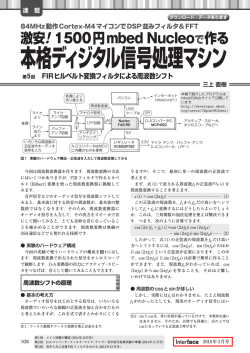
Boundary Conditions at a Interface Between Different Media
Now we think a interface which is at the boundary medium 1 and 2 as shown in Fig.1.
From Gauss law, we can get the following for the Gauss box which include the interface
inside the box,
Z
Z
V
dr ∇
· D} =
| {z
ρ
S
D · dS
(38)
In the limit that the Gauss box is very thin (δh → 0)
Z
V
drρ = Qbox = n · [D1 − D2 ]S
(39)
where vector n means the surface normal unit vector pointing from media 2 to 1.
n · [D1 − D2 ] = Qbox /S = σ12
(40)
where σ12 means the interface charge density. From ∇ · B = 0
n · [B1 − B2 ] = 0
(41)
As shown in Fig. 2 for a general vector field V(r), Stokes theorem gives
I
V · dr = (I) + (II) + (III) + (IV)
= Vx (x0 , y0 )dx + Vy (x0 + dx, y0 )dy + Vx (x0 , y0 + dy)(−dx) + Vy (x0 , y0 )(−dy)
5
= Vx (x0 , y0 )dx + [Vy (x0 , y0 ) +
−[Vx (x0 , y0 ) +
µ
=
∂Vy
dx]dy
∂x
∂Vx
dy]dx − Vy (x0 , y0 )dy
∂y
∂Vx
∂Vy
−
dxdy = (rotV)z dxdy
∂x
∂y
δr
medium 1
n
δh
t1
medium 2
t2
b
Figure 1: Gauss and Stokes box
y
(x0, y0+dy)
(III)
(x0+dx, y0+dy)
(IV)
(II)
(I)
(x0, y0)
(x0+dx, y0)
x
Figure 2: Stokes theorem
From Eq.(3) and Stokes theorem we can get
I
C
E · dr =
Z
S
rotE · dS
∂B
· bdS
S ∂t
∂B
δr[E1 · t1 + E2 · t2 ] = −
· bδrδh −→ 0
∂t
t = t1 = −t2
= −
(42)
Z
t · [E1 − E2 ] = 0
(43)
(44)
(45)
(46)
Here b is the unit vector defined by b = n × t. From Eq.(4)
I
C
H · dr =
Z
S
rotH · dS
Z µ
=
J+
S
6
∂D
∂t
(47)
· bdS
(48)
µ
∂D
δr[H1 · t1 + H2 · t2 ] =
J+
· bδrδh −→ J · bδrδh
∂t
t · [H1 − H2 ] = Js [≡ surface current density(Am−1 )]
3
(49)
(50)
Reflection and Transmission
Now we define the incident plane wave as
E = E0 ei(k·r−ωt) ,
ω = ω(k),
B=
k × E0 i(k·r−ωt)
e
ω
(51)
reflected wave as
′
′
E′ = R0 ei(k ·r−ω t) ,
ω ′ = ω ′ (k ′ ),
B′ =
k′ × R0 i(k′ ·r−ω′ t)
e
ω′
(52)
transmitted wave as
E′′ = T0 ei(k
′′ ·r−ω ′′ t)
,
ω ′′ = ω ′′ (k ′′ ),
B′′ =
k′′ × T0 i(k′′ ·r−ω′′ t)
e
ω ′′
(53)
Ep
Rp
θ
Es
θ
k
y
k’
medium 1
Rs
θ’
x
x
medium 2
z
Tp
θ”
z
Ts
k”
Figure 3: Reflection and Transmission of Light
From Fig.3
k = (k sin θ, 0, k cos θ)
′
k
′′
k
′
′
′′
′′
′
(54)
′
= (k sin θ , 0, k cos θ ),
′′
e
i(π−θ′ )
′
= − cos θ + i sin θ
′
′′
= (k sin θ , 0, k cos θ )
The p-wave has the components of x and z, but s-wave has only the y component.
6
(55)
(56)
6
光(電磁場)は横波であるので、光の進行方向に対して2つの偏光成分を持つ。(デジタル腕時計の液晶
7
3.1
t · [E1 − E2 ] = 0
Condition I:
From Eq.(46) the tangential component of the electric field become
Ep cos θe
i(k sin θx−ωt)
′
i(k′
+ Rp cos θ e
Ex + Ex′ = Ex′′
sin θ′ x−ω ′ t)
at z = 0
(57)
′′ i(k′′ sin θ′′ x−ω ′′ t)
= Tp cos θ e
(58)
For any x at z = 0 this condition should be satisfied, then
ω = ω ′ = ω ′′
′
(59)
′
′′
′′
(60)
because k = k ′
(61)
k sin θ = k sin θ = k sin θ
The magnitude of the wavevector is given by Eq.(21)
sin θ = sin θ′ = sin(π − θ′ ),
The incident angle equals to the reflection angle, and
k sin θ = ñ1
ω
ω ′′
sin θ = k ′′ sin θ′′ = ñ2
sin θ′′
c
c
(62)
Then we can get Snell’s law because ω = ω ′′
The Eq.(58) becomes
ñ1 sin θ = ñ2 sin θ′′
(63)
(Ep − Rp ) cos θ = Tp cos θ′′
(64)
From Fig.3 we can get
Ep cos θ
−Rp cos θ
Tp cos θ′′
Es
Rs
Ts
E0 =
, R0 =
, T0 =
−Ep sin θ
−Rp sin θ
−Tp sin θ′′
(65)
For y-direction we can get the condition
Ey + Ey′ = Ey′′
at z = 0
i(k′′
(Es + Rs )ei(k sin θx−ωt) = Ts e
sin θ′′ x−ωt)
(Es + Rs ) = Ts
3.2
Condition II:
(66)
(67)
(68)
n · (B1 − B2 ) = 0
For the boundary condition in Eq.(41)
k × E0
¯
¯
i
¯
¯
= ¯ k sin θ
¯
¯ Ep cos θ
j
k
0
k cos θ
Es −Ep sin θ
¯
¯
¯
¯
¯
¯
¯
= k[−iEs cos θ + j(Ep cos2 θ + Ep sin2 θ) + kEs sin θ]
ωB = k × E0
=
−kEs cos θ
kEp
kEs sin θ
(69)
(70)
表示板 (ほぼ直線偏光?)を偏光サングラスで見ながら回転させると 90 °毎に明暗が見える。)s 波(s 偏光)
は界面に平行な成分で、p 波(p 偏光)は s 波に垂直な成分である。電場成分が紙面に垂直なので s 波は TE
(transverse electric) wave,磁場成分が紙面に垂直なので p 波は TM (transverse magnetic) wave とも言わ
れる。
8
k′ × R0
¯
¯
i
¯
¯
= ¯ k sin θ
¯
¯ −Rp cos θ
¯
¯
¯
¯
¯
¯
¯
j
k
0
−k cos θ
Rs −Rp sin θ
= k[iRs cos θ + j(Rp cos2 θ + Rp sin2 θ) + kRs sin θ]
′
′
ωB = k × R0
=
kRs cos θ
kRp
kRs sin θ
¯
¯
i
¯
¯ ′′
= ¯ k sin θ′′
¯
¯ Tp cos θ ′′
k′′ × T0
(72)
j
k
′′
0 k cos θ′′
Ts −Tp sin θ′′
¯
¯
¯
¯
¯
¯
¯
= k ′′ [−iTs cos θ′′ + j(Tp cos2 θ + Tp sin2 θ′′ ) + kTs sin θ′′ ]
ωB′′ = k′′ × T0 =
−k ′′ Ts cos θ′′
k ′′ Tp
k ′′ Ts sin θ′′
(71)
(73)
(74)
The boundary condition Bz + Bz′ = Bz′′ becomes
k sin θ
k ′′ sin θ′′
′′
′′
(Es + Rs )ei(k sin θx−ωt) =
Ts ei(k sin θ x−ωt)
ω
ω
n˜1 (Es + Rs ) sin θ = n˜2 Ts sin θ′′
(75)
(76)
Es + Rs = Ts
(77)
We used Snell’s law in the last equation. This equation is the same as Eq.(68).
3.3
n · (D1 − D2 )
Condition III:
For the boundary condition in Eq.(40)
ϵ˜1 ϵ0 (Ez + Ez′ ) = ϵ˜2 ϵ0 Ez′′ + σ12
ϵ˜1 ϵ0 (−Ep sin θ − Rp sin θ)e
i(k sin θx−ωt)
(78)
′′
i(k′′ sin θ′′ x−ωt)
= ϵ˜2 ϵ0 (−Tp sin θ )e
Z
σ12 (r, t) = δ(z)
Z
∞
−∞
dk
∞
−∞
+ σ12 (r, t)
dωσ12 (k, ω)ei(kx−ωt) (79)
In Eq.(79)
we used the Fourier transformed charge
density σ12 (k, ω). If we apply
RR
RR
′ x−ω ′ t)
′
′
2
−i(k
2
(1/2π)
dxdte
, then we use (1/4π )
dxdtei(k sin θx−k x) e−i(ω−ω )t = δ(k sin θ−
k ′ )δ(ω − ω ′ ) and the above equations are held at z = 0
ϵ˜1 ϵ0 (−Ep sin θ − Rp sin θ)δ(k sin θ − k ′ )δ(ω − ω ′ ) = −ϵ˜2 ϵ0 Tp sin θ′′ δ(k ′′ sin θ′′ − k ′ )
′
δ(ω − ω ) +
Z Z
dk ′′′ dω ′′′ σ12 (k ′′′ , ω ′′′ )δ(k ′′′ − k ′ )δ(ω ′′′ − ω) (80)
σ12 (k sin θ, ω)
ϵ0
′
From Snell s law
σ12 (k sin θ, ω)
n˜1 (Ep + Rp ) = n˜2 Tp +
ϵ0 n˜1 sin θ
n˜1 2 (Ep + Rp ) sin θ = n˜2 2 Tp sin θ′′ +
(81)
(82)
(83)
Here we can neglect the σ12 (k sin θ, ω) term 7 .
7
Laser light(10 mW He-Ne, focused to 20 µm, 1026 photons/s/m2 = I/(h̄ω) I = cϵ0 E02 /2 (J/m2 /s
= W/m2 ) c=299792458 m, E0 = 1.5 × 10⁵ V/m ) Bright sunlight (average 480nm, 1018 photons/s/m2
9
Condition IV: t · [H1 − H2 ] = Js
3.4
Hx + Hx′ = Hx′′ + (Js )x
Hy +
Hy′
=
Hy′′
+ (Js )y
Bx = µµ0 Hx , ......
Z Z
µ
−
3.5
dkdω[Js (k, ω)]x ei(kx−ωt) , ..
[Js (r, t)]x =
kEs cos θ kRs cos θ i(k sin θx−ωt)
+
e
µ1 µ0 ω
µ1 µ0 ω
n˜1 cos θ
(Es − Rs )
µ1
µ
kEp
kRp
+
ei(k sin θx−ωt)
µ1 µ0 ω µ1 µ0 ω
n˜1
(Ep + Rp )
µ1
(84)
(85)
(86)
(87)
k ′′ Ts cos θ′′ i(k′′ sin θ′′ −ωt)
e
+ [Js (r, t)]x
µ2 µ0 ω
n˜2 cos θ′′
Ts + cµ0 [Js (k sin θ, ω)]x
(88)
µ2
k ′′ Tp i(k′′ sin θ′′ x−ωt)
e
+ [Js (r, t)]y
(89)
µ2 µ0 ω
n˜2
Tp + cµ0 [Js (k sin θ, ω)]y
(90)
µ2
= −
=
=
=
Reflection and Transmission Coefficients
In the end we can obtain the following equation for p-wave
(Ep − Rp ) cos θ = Tp cos θ′′
σ12 (k sin θ, ω)
n˜1 (Ep + Rp ) = n˜2 Tp +
ϵ0 n˜1 sin θ
n˜1
n˜2
(Ep + Rp ) =
Tp + cµ0 [Js (k sin θ, ω)]y
µ1
µ2
(91)
Es + Rs = Ts
n˜1 cos θ
n˜2 cos θ′′
(Es − Rs ) =
Ts + cµ0 [Js (k sin θ, ω)]x
µ1
µ2
(94)
(92)
(93)
and for s-wave
3.5.1
(95)
Usual Solution: No Absorption in the Media 1 and 2.
Here we assume that σ12 (k sin θ, ω) = 0, Im(ñ1,2 ) = 0 (later we will consider the case
that the optical constant is complex, i.e. the medium absorb the light.), µ1 = µ2 =
1, [Js (k sin θ, ω)]x = 0, [Js (k sin θ, ω)]y = 0. Then for p-wave we can get
(Ep − Rp ) cos θ = Tp cos θ′′
(96)
n1 (Ep + Rp ) = n2 Tp
(97)
and for s-wave
Es + Rs = Ts
(98)
′′
n1 cos θ(Es + Rs ) = n2 cos θ Ts
(99)
E0 = 18V/m.) For electrochemical systems σ12 (k sin θ √
= 0, ω√= 0) is the order of 10 µC/cm2 = 0.1
2
C/m (fully dissociated 3-mercaptopropionic acid in the 3 × 3 structure on Au(111) surface = 0.74
C/m2 ). σ12 /ϵ0 = (1 ∼ 8) × 1010 V/m. However, the surface charge at the electrode in the ω = 0 limit do
not couple to the photon field at ω = ωphoton .
10
If we define the amplitude reflection coefficient r and the amplitude transmission
coefficient for s- and p-waves,
rp ≡
tp ≡
rs ≡
ts ≡
Rp
Ep
Tp
Ep
Rs
Es
Ts
Es
(100)
(101)
(102)
(103)
(1 − rp ) cos θ = tp cos θ′′
(104)
n1 (1 + rp ) = n2 tp
(105)
(106)
and for s-wave
1 + rs = t s
(107)
′′
n1 cos θ(1 − rs ) = n2 cos θ ts
(108)
We finally get the Fresnel(フレネル) equations
rp =
tp =
rs =
ts =
−n1 cos θ′′ + n2 cos θ
n1 cos θ′′ + n2 cos θ
2n1 cos θ
n1 cos θ′′ + n2 cos θ
n1 cos θ − n2 cos θ′′
n1 cos θ + n2 cos θ′′
2n1 cos θ
n1 cos θ + n2 cos θ′′
(109)
(110)
(111)
(112)
The reflectance R is defined as the ratio of the reflected power (or flux)
to the incident power of the light
R=
I ′ A cos θ′
I′
n1 R2 /(2cµ0 )
=
=
= r2
IA cos θ
I
n1 E 2 /(2cµ0 )
(113)
The radiant flux density I (W/m2 ) is given by the averaged Poynting vector < E×H >=
ñE 2 /(2cµ0 ). In the same way the transmittance T may be given by
T =
I ′′ A cos θ′′
vt ϵt T 2 cos θ′′
n2 cos θ′′ 2
=
=
t
IA cos θ
vi ϵi E 2 cos θ
n1 cos θ
(114)
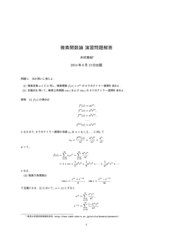
In Fig.4 and Fig.5 the r, t, R, and T are plotted for the air(1)|water(2) [air→water]
and water(1)|air(2) [water→air] interface, respectively. 8 In the both cases ts and tp are
8
Fig.5 の右側の図より水面からの反射光はすべての角度で s 波の方が強く散乱されることがわかる。従っ
て、s 波をカットするように偏光サングラスがセットアップされていることが望ましい。s 波は、水平方向の
電場ベクトルをもつ波である。従って、偏光サングラスは鉛直方向の電場ベクトルをもつ光を通すように作
られている。水面からの反射光を偏光サングラスを通してみると、通常かける方向で光は最小になり、90度
めがね(もしよければ頭を!)回転すると反射光が最大になるのが観測される。LCD(liquid crystaldisplay)
や液晶をつかった時計・表示板をみると、右方向に 45 度回すと真っ暗になる。偏光面を 45 度にして偏光サ
ングラスをかけても見えるようにしているようだ。
また、水面 | 空気界面からの散乱では、後に示すように 48.66 °以上では全反射(反射率=1、透過率=0)
する。
11
θ
sin(π/2 − θ)
=
cos θ
A
S
S cos θ
=
A
A
=
s
Figure 4: Angle dependency of the intensity of light
always positive, and this means the phase shifts of transmitted wave are always zero.
For the case of air(1)|water(2) [air→water] rs is always negative and rp is positive for
θ < θp,air→water and become negative for θ > θp,air→water . These means that the phase
shift is π for reflected s wave and phase shift become 0 to π at θp,air→water . For the case of
water(1)|air(2) [water→air] rs is always positive and rp is negative for θ < θp,water→air
and become positive for θ > θp,water→air . These means that the phase shift is 0 for
reflected s wave and phase shift become π to 0 at θp,water→air . In Appnedix the plot of
the phase shift of the reflected s and p waves are shown. We also shown the condition
of the black film formation in Appendix.
Air(n1=1)|Water(n2=1.332) Interface :He-Ne Laser
Air(n1 =1)|Water(n2 =1.332) Interface: He-Ne Laser
1
0.8
1
0.6
0.4
0.2
0
0.8
tp
R or T
ts
rp
-0.2
-0.4
rs
0.4
0.2
-1
0
10
20
30
40
50
60
incident angle (degree)
70
80
Tp
0.6
-0.6
-0.8
0
Ts
90
Rs
0
10
20
Rp
30
40
50
60
70
incident angle (degree)
80
90
Figure 5: Reflection and transmission of He-Ne laser light at air|water interface
3.5.2
Brewster angle
In Figs.4 and 5, we can find the point rp = Rp = 0 9 and this condition is given by
µ
′′
−n1 cos θ + n2 cos θ = −n1
(cos θ′′ sin θ′′ − cos θ sin θ) =
′′
sin θ
cos θ −
cos θ = 0
sin θ′′
′′
′′
′′
(115)
′′
eiθ + e−iθ eiθ − e−iθ
eiθ + e−iθ eiθ − e−iθ
−
2
2i
2
2i
9
レーザー共振器内に,Brewster 角に設定したシリカ板を置けば p 偏光は反射されずに透過するが、s 偏光
は行き帰りで2回反射されるために減衰する。
12
Water(n1=1.332)|Air(n2=1) Interface :He-Ne Laser
Water(n1 =1.332)|Air(n2 =1) Interface: He-Ne Laser
3
1
2.5
Ts
Tp
Rs
Rp
0.8
2
ts
1
0.5
0.6
R or T
tp
1.5
0.4
rs
0.2
rp
0
-0.5
0
0
5
10
15 20 25 30 35
incident angle (degree)
40
45
50
0
5
10
15 20 25 30 35
incident angle (degree)
40
45
50
Figure 6: Reflection and transmission of He-Ne laser light at water|air interface
′′
′′
e2iθ − e−2iθ
e2iθ − e−2iθ
−
4i
4i
2i sin(2θ′′ ) − 2i sin(2θ)
=0
4i
=
=
Then
π
−θ
2
The angle between the reflected light and the transmitted light is orthogonal.
θ′′ =
n2 sin θ′′ = n2 sin(π/2 − θ) = n2 cos θ = n1 sin θ
−1
µ
θBrewster = tan
n2
n1
(116)
(117)
(118)
From air to water reflection, the Brewster angle is 53.10 degree, and from water to
air the angle is 36.90 degree.
3.6
Total Internal Reflection
Now we will consider the case that the angle θ′′ between the transmitted wave and the
surface normal is 90 degree, i.e., sin θc′′ = (n1 /n2 ) sin θc = 1. Here
θc = sin−1
n2
n1
(119)
and should n2 < n1 . For water to air reflection θc = 48.66 degree. In this situation the
transmitted light is along the surface parallel direction. What happens if θ > θc ?
cos θ′′ =
q
q
q
1 − sin2 θ′′ = i sin2 θ′′ − 1 = i (n1 /n2 )2 sin2 θ − 1
(120)
The transmitted wave can be written as
E′′ = T0 ei(k
′′ ·r−ω ′′ t)
(121)
i(k′′ sin θ′′ x+k′′ cos θ′′ z−ω ′′ t)
= T0 e
i(k′′
= T0 e
sin θ′′ x−ω ′′ t)
n ω sin θ ′′
i 2 c
x
= T0 e
−k′′
e
′′
e−iω t e−
13
√
(n1 /n2
n2 ω
√
(122)
)2
sin2
θ−1z
(n1 /n2 )2 sin2 θ−1
z
c
(123)
(124)
2n2 ω
√
(n1 /n2 )2 sin2 θ−1
z
c
The transmitted light intensity decays as e−
. The decay length is
the order of wavelength because c/ω = λ/2π. The Poynting vector S in the z direction
in the medium 2,
z · 〈S〉 =
=
=
1
Re(E × B′′∗ ) · z
2µ0 µ
1
Re[E × (k′′ × E′′ )∗ ] · z
2µ0 µω
1
′′
′′
Re[k′′ |E′′ |2 − E ∗ (k
· E′′}) · z
| {z
2µ0 µω
(125)
(126)
(127)
=0
=
1
Re(
2µ0 µω
′′
z
| ·{zk }
|E′′ |2 )
(128)
k′′ cos θ=pure imaginary
= 0
(129)
Thereby the energy flux to ẑ direction in the medium 2 is zero. We call this exponentialdecay wave as evanescent wave, and is used for some interface spectroscopies to detect
species located at the evanescent field.
3.6.1
Phase Shift of the Total Internal Reflection Wave
For the total internal reflection the amplitudes of the incident wave and the reflected
wave are the same but there is a phase shift between them.
a2 − b2 − 2iab
n2 cos θ − n1 cos θ′′
a − ib
=
=
= e−iδp
n2 cos θ + n1 cos θ′′
a + ib
a2 + b2
rp =
(130)
q
a = n2 cos θ, b = n1 (n1 /n2 )2 sin2 θ − 1
2ab
tan(δp ) =
2
a − b2
c2 − d2 − 2icd
n1 cos θ − n2 cos θ′′
c − id
=
rs =
=
= e−iδs
n1 cos θ + n2 cos θ′′
c + id
c2 + d2
(131)
(132)
(133)
q
c = n1 cos θ,
2cd
tan(δs ) = 2
c − d2
3.7
d = n2 (n1 /n2 )2 sin2 θ − 1
(134)
(135)
Metal Surface
For the metal surface the optical index becomes complex because some part of the light
is absorbed by the electronic transition of metallic electrons at Fermi level.
ñ2 = n2 + iκ2 , k ′′ = ñ2 ω/c = (n2 + iκ2 )ω/c
(136)
From the condition I,
n1 sin θ = ñ2 sin θ′′ = (n2 + iκ2 ) sin θ′′
(137)
Now θ′′ is complex, and we define[13]
ñ2 cos θ′′ ≡ u2 + iv2 ,
(u2 + iv2 )2
Here u2 and v2 are real.
n2
= ñ22 cos2 θ′′ = ñ22 (1 − 21 sin2 θ) = ñ22 − n21 sin2 θ
ñ2
14
(138)
(139)
1
phase shift / pi
0.8
rp
0.6
rs
0.4
0.2
0
45
50
55
60
65
70
75
80
incident angle (degree)
85
90
Figure 7: Phase shift of the TIR wave (He-Ne laser) from water|air interface.
For the real and imaginary parts of Eq.(139)
u22 − v22 = n22 − κ22 − n21 sin θ2
2u2 v2 = 2n2 κ2
(140)
(141)
Then we can get
u22 =
v22 =
n22 − κ22 − n21 sin2 θ +
q
(n22 − κ22 − n21 sin2 θ)2 + 4n22 k22
−(n22 − κ22 − n21 sin2 θ) +
q2
(n22 − κ22 − n21 sin2 θ)2 + 4n22 k22
2
(142)
(143)
For p wave,
ñ2 cos θ − n1 cos θ′′
ñ2 cos θ − n1 ñ2 cos θ′′
= 22
′′
ñ2 cos θ + n1 cos θ
ñ2 cos θ + n1 ñ2 cos θ′′
(n22 − κ22 + 2in2 κ2 ) cos θ − n1 (u2 + iv2 )
(n22 − κ22 + 2in2 κ2 ) cos θ + n1 (u2 + iv2 )
rp ≡ ρp eiφp =
=
ρ2p
(144)
(145)
¯
¯
¯ (n2 − κ2 ) cos θ − n u + i(2n κ cos θ − n v ) ¯2
1
2
2
2
1
2
¯ 2
¯
2
= ¯ 2
¯
¯ (n2 − κ22 ) cos θ + n1 u2 + i(2n2 κ2 cos θ + n1 v2 ) ¯
(146)
[(n22 − κ22 ) cos θ − n1 u2 ]2 + (2n2 κ2 cos θ − n1 v2 )2
[(n22 − κ22 ) cos θ + n1 u2 ]2 + (2n2 κ2 cos θ + n1 v2 )2
(147)
=
tan φp = {[(n22 − κ22 ) cos θ + n1 u2 ](2n2 κ2 cos θ − n1 v2 ) − [(n22 − κ22 ) cos θ − n1 u2 ]
=
tp =
=
τp2 =
tan χp =
(2n2 κ2 cos θ + n1 v2 )}/[(n22 − κ22 )2 cos2 θ − n21 u22 + 4n22 κ22 cos θ − n21 v22 ]
2n2 u2 κ2 − (n22 − k22 )v2
2n2 cos θ 2
(148)
(n2 + κ22 )2 cos2 θ − n21 (u22 + v22 )
2n1 cos θ
2n1 ñ2 cos θ
τp eiχp =
=
(149)
′′
n1 cos θ + ñ2 cos θ
n1 ñ2 cos θ′′ + ñ22 cos θ
2n1 n2 cos θ + i2n1 κ2 cos θ
(150)
n1 u2 + (n22 − κ22 ) cos θ + i(n1 v2 + 2n2 κ2 cos θ)
n22 + κ22
4n21 cos2 θ =
(151)
[n1 u2 + (n22 − κ22 ) cos θ]2 + (n1 v2 + 2n2 κ2 cos θ)2
n1 κ2 u2 + κ2 (n22 − κ22 ) cos θ − n1 n2 v2 − 2n22 κ2 cos θ
2n1 cos θ
(152)
2n2 cos θ[n21 u2 + n1 (n22 − κ22 ) cos θ + n1 κ2 v2 + 2n2 κ22 cos θ]
15
The tp in the book ”Born and Wolf, Principles of Optics (7th ed) p.575 Eqs.(14) and
(15)”[13] may be wrong.
For s wave
n1 cos θ − ñ2 cos θ′′
n1 cos θ − (u2 + iv2 )
=
′′
n1 cos θ + ñ2 cos θ
n1 cos θ + u2 + iv2
¯
¯
¯ n1 cos θ − u2 − iv2 ¯2
(n1 cos θ − u2 )2 + v22
¯
¯
¯ n cos θ + u + iv ¯ = (n cos θ + u )2 + v 2
1
2
2
1
2
2
−2v2 n1 cos θ
n21 cos2 θ − u22 − v22
2n1 cos θ
2n1 cos θ
τs eiχs =
=
′′
n1 cos θ + ñ2 cos θ
n1 cos θ + u2 + iv2
¯2
¯
¯
¯
4n21 cos2 θ
2n1 cos θ
¯ =
¯
¯ n cos θ + u + iv ¯
(n1 cos θ + u2 )2 + v22
1
2
2
2v2 n1 cos θ
v2
− 2
=−
2
n1 cos θ + u2
2n1 cos θ + 2u2 n1 cos θ
rs = ρs eiφs =
(153)
ρ2s =
(154)
tan φs =
ts =
τs2 =
tan χs =
(155)
(156)
(157)
(158)
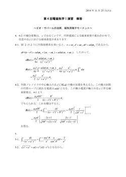
For He-Ne laser (632.8 nm) the reflectance at the air|gold surface (n = 0.181, κ =
2.99) is shown in Fig.7. For IR light at 3100 nm the reflectance at the air|gold surface
(n = 1.728, κ = 19.2) is shown in Fig. 8.
1
250
s-wave
Rs
200
phase shift (degree)
0.98
reflectance
0.96
0.94
0.92
Rp
0.9
150
p-wave
100
50
0.88
0.86
0
0
10
20
30 40 50 60 70
incident angle (degree)
80
90
0
10
20
30
40
50
60
70
incident angle (degree)
80
90
80
90
Figure 8: He-Ne laser (632.8 nm) reflection from air|Au surface
1
200
Rs
0.98
180
phase shift (degree)
reflectance
s-wave
160
0.96
0.94
0.92
Rp
0.9
0.88
0.86
140
120
100
80
60
p-wave
40
0.84
20
0.82
0
0
10
20
30 40 50 60 70
incident angle (degree)
80
90
0
10
20
30
40
50
60
70
incident angle (degree)
Figure 9: IR light (3100 nm) reflection from air|Au surface
The intensities of light in the z- and y-component per unit area on the Au surface
16
becomes
(Ep⊥ /Ep )2 / cos θ ≡ |E0z + R0z |2 /Ep2 / cos θ = | − Ep sin θ − Rp sin θ|2 /Ep2 / cos θ
= | − Ep sin θ − rp Ep sin θ|2 /Ep2 / cos θ
= | − Ep sin θ − (ρp cos φp + iρp sin φp )Ep sin θp |2 /Ep2 / cos θ
(Es∥ /Es )2 / cos θ
= sin θ2 (1 + 2ρp cos φp + ρ2p )/ cos θ
(159)
|E0y + R0y | /Es2 / cos θ
|Es + Rs |2 /Es2 / cos θ = |Es
(1 + 2ρs cos φs + ρ2s )/ cos θ
(160)
≡
2
=
=
+ rs Es |2 /Es2 cos θ
These equations give the basics of the surface sensitivity of the RAIRS(Reflection Absorption Infrared Spectroscopy) and Polarization-Modulation FTIR spectroscopy, and the
angle dependence are shown in Fig.9. The 180 degree phase change of s-wave leads to
destructive interference and no interaction with surface dynamic dipoles from molecular vibrations. 10 For the surface normal component of the p-wave the interference is
constructive and it can excite the dynamic dipole perpendicular to the surface. The
excitation is efficient for a higher angle of incidence.
45
40
35
30
25
p-normal Eq.(159)
20
15
10
5
s-parallel Eq.(160)
0
0
10
20
30
40
50
60
incident angle (degree)
70
80
90
∥
Figure 10: plots of (Ep⊥ /Ep )2 / cos θ and (Es /Es )2 / cos θ. The IR light is 3100 nm and
∥
the IR light is reflected from the air|Au surface. (Es /Es )2 / cos θ is negligible because
the phase shift is almost 180 degree between the incident wave and the reflected wave.
4
Surface Plasmon
The electronic charges on metal boundary can perform coherent fluctuations which are
called surface plasma oscillations. The fluctuations are confined at the boundary and
vanishes both sides of the metal surface. This plasmon waves have p-character because the
surface charge induce the discontinuity of the electric field in the surface normal z-direction,
but s-waves has only Ey component (no Ez component).
Now we consider the air(medium 2)|metal(medium 1) surface where the electric fields
are dumped both side of the interface.
Using a pure imaginary kz2 the electric and magnetic field in medium 2(air, z > 0)
10
The surface parallel x-component (not shown here) of p-wave is also negligible.
17
can be given by
E2
(161)
0
= Hy2 ei(kx2 x+kz2 z−ωt)
0
(162)
H2
Ex2
= 0 ei(kx2 x+kz2 z−ωt)
Ez2
Using a pure imaginary kz1 the electric and magnetic field in medium 1(metal, z > 0)
can be given by
E1
(163)
0
= Hy1 ei(kx1 x−kz1 z−ωt)
0
(164)
H1
Ex1
= 0 ei(kx1 x−kz1 z−ωt)
Ez1
From the Condition I, we can get
kx1 = kx2 = kx
(165)
Ex1 = Ex2
(166)
Ez1 = Ez2
(167)
From condition IV,
Hy1 = Hy2
(168)
here we assume (Js )y ≈ 0
(169)
From condition III,
ϵ̃1 ϵ0 Ez1 = ϵ̃2 ϵ0 Ez2
(170)
here we assume
σ12 (kx , ω) ≪ D1z , D2z
(171)
From Eq.4 and J ≈ 0
rotH =
∂D
¯ ∂t
¯ i
¯
¯ ∂
rotH = ¯ ∂x
¯
¯ 0
(172)
j
∂
∂y
Hyi
¯
k ¯¯
∂
∂
∂ ¯
Hyi + k Hyi
∂z ¯¯ = −i
∂z
∂x
0 ¯
(173)
From the i component of the above equation,
Ex1 = Ex2 then
ikz1 Hy1 = −iωϵ0 ϵ̃1 Ex1
(174)
−ikz2 Hy2 = −iωϵ0 ϵ̃2 Ex2
(175)
kz1
kz2
Hy1 +
Hy2 = 0
ωϵ0 ϵ̃1
ωϵ0 ϵ̃2
(176)
18
Hy1 = Hy2 then
kz1 kz2
+
=0
ϵ̃1
ϵ̃2
(177)
From Eqs.(21) and (26)
2
= ϵ̃i
k 2 = kx2 + kzi
kx2
kx2
µ ¶2
ω
c
µ ¶2
(178)
ω
2
− kz1
c
µ ¶2
ω
2
− kz2
= ϵ̃2
c
µ ¶2 µ
¶2
ω
ϵ̃2
= ϵ̃2
− − kz1
c
ϵ̃1
= ϵ̃1
(179)
(180)
From the last two equations Eqs.(179) and (180).
µ
kx2
=
ϵ̃1 ϵ̃2
ϵ̃1 + ϵ̃2
Ã
2
kz1
=
Ã
2
kz2
=
¶ µ ¶2
ω
c
ϵ̃21
ϵ̃1 + ϵ̃2
ϵ̃22
ϵ̃1 + ϵ̃2
(181)
!µ 
2
ω
c
(182)
ω
c
(183)
!µ 
2
If we remind that ϵ̃1 = ϵ′1 + iϵ′′1 , ϵ̃2 = ϵ2
kx2
µ ¶2
=
ω
c
(ϵ′1 + iϵ′′1 )ϵ2
(ϵ′1 + iϵ′′1 ) + ϵ2
ω
c
ϵ′ (ϵ′ + ϵ2 ) + ϵ1 2 + i[ϵ′′1 (̸ ϵ′1 + ϵ2 )− ̸ ϵ′1 ̸ ϵ′′1 ]
ϵ2 1 1
′′
(ϵ′1 + ϵ2 )2 + ϵ1 2
µ ¶2
=
′′
(184)
If we assume ϵ′′1 < |ϵ′1 |
Re(kx ) =
ω
c
Im(kx ) =
ω
c
µ
µ
ϵ′1 ϵ2
ϵ′1 + ϵ2
ϵ′1 ϵ2
′
ϵ1 + ϵ2
¶1/2
(185)
¶3/2
ϵ′′1
′
2ϵ12
(186)
The surface plasmon decay in x-direction can be evaluated from Im(kx ) because the
intensity decreased as exp[−2Im(kx )x]. The decay length L12 may be obtained as
L12 = [2Im(kx )]−1 =
c
ω
µ
ϵ′1 ϵ2
ϵ′1 + ϵ2
¶−3/2
′
ϵ12
ϵ′′1
(187)
For the water|metal interface the decay lengths L12 are 6.4 µm for gold (16.6 µm for air|gold
surface), 12.3 µm for silver, and 5.5 µm for aluminum. The decay length L12 is the key
parameter to carry out a SPR imaging measurements 11 . In addition there is a temporal
decay in ω, please refer the Raether’s book for details[1].
11
この議論から SPR において横方向のイメージングの分解能はマイクロメータサイズ以上であることがわ
かる。L12 の小さいアルミニウムを使って、生きた細胞を SPR イメージングで観測した例も報告されてい
る。[15]
19
√
The dispersion relation kx vs ω become close to the light line ϵ2 ω/c at small kx ,
because in the limit that ω → 0, ϵ′1 >> ϵ2 . At large kx the denominator of Eq.(185)
becomes zero
ϵ′1 + ϵ2 = 0
(188)
For simple metals the dielectric constant is given by the plasma frequency ωp [16]
ϵ′1 = 1 −
ωp2
ω2
12
(189)
From Eqs.(188) and (189) the surface plasma frequency ωsp may be obtained as
ωsp = ωp √
1
1 + ϵ2
(190)
In Fig.10 we plot the dispersion relation Eq.(185).
3.5
bulk plasmon energy
3
energy (eV)
2.5
surface plasmon energy
2
1.5
1
0.5
0
0
0.05 0.1 0.15 0.2 0.25 0.3 0.35 0.4 0.45 0.5
kx (108 m-1)
Figure 11: Surface plasmon dispersion ω(kx ) on gold surface. The vertical axis is scaled
√
as h̄ω (eV). The straight solid line in the figure shows the light line kx = ϵ2 ω/c. The
energy of bulk plasmon is 3.22 eV, and that of surface plasmon is 2.28 eV and shown as
the arrows in the figure.
In the z-direction the electric field of the surface plasmon decays as Ez ∝ e−|kzi ||z| .
If we assume ϵ′′1 < |ϵ′1 | again,
Ã
2
kz1
≈
Ã
2
kz2
≈
′
ϵ12
ϵ′1 + ϵ2
ϵ22
ϵ′1 + ϵ2
!µ 
2
ω
c
(191)
ω
c
(192)
!µ 
2
ϵ′1 + ϵ2 < 0 then kzi is purely imaginary. For He-Ne laser light (632.8 nm) on the gold
surface
1/Re(kz1 )(metal) = 32 nm, 1/Re(kz2 )(air) = 285 nm
(193)
From the k component of rotH = ∂D/∂t [cf. Eq.(173)]
∂Hy1
∂x
∂Hy2
∂x
= ikx1 Hy1 = −iωϵ0 ϵ˜1 Ez1
(194)
= ikx2 Hy2 = −iωϵ0 ϵ˜2 Ez2
(195)
12
電子線を金属に照射して電子線のエネルギー損失を測定するとその金属のプラズマ振動数が測定される。
表面・界面にのみ存在する表面プラズモンも反射電子線のエネルギー損失から測定される。
20
From the i component of Eqs.(172-173) and Eq.(194)
Hy1 = −
Ez1
Ex1
(196)
kx1
kz1
ωϵ0 ϵ˜2 Ez2
ωϵ0 ϵ˜2 Ex2
=−
=
kz2
kx2
kx2
= −
kz2
=
Hy2
Ez2
Ex2
ωϵ0 ϵ˜1 Ex1
ωϵ0 ϵ˜1 Ez1
=−
kz1
kx1
(197)
(198)
(199)
(200)
5
Excitation of Surface Plasmon by Light
5.1
ATR (Attenuated Total Reflection) Coupler Method
We will consider the situation that the light is reflected from a metal surface covered
with a dielectric medium (ϵpr > 1) , e.g. with a BK7 half cylinder glass prism (n=1.515
at 633 nm) or SF10 glass prism (n=1.723 at 643.8 nm). The x and z components of the
wavevector in the prism are given by
ω
√ ω
kxpr = ϵpr sin θpr = npr sin θpr
(201)
c
c
ω
√ ω
kzpr = ϵpr cos θpr = npr cos θpr
(202)
c
c
Here pr means the prism.
θpr
kxpr
d1
εpr
ε1
ε2
x
y
z
Figure 12: Schematic diagram of ATR coupler: Kretschmann-Raether type
The resonance condition of the light in the prism with the surface plasmon
at metal(1)|air(2) interface (Kretschmann-Raether configuration) is 13
kxpr = kxsp
(203)
ATR カプラーには、プリズム | 金属薄膜 | 試料系の Kretschmann-Raether 型とプリズム | 薄層(波長程
度の厚み)試料 | 金属の Otto 型がある。Otto 型は薄層の gap 調整が必要であり、Kretschmann-Raether 型
が主に使用されている。ただし、Kretschmann-Raether 型では膜厚(50nm 程度)を慎重に制御して金属を
ガラスに真空蒸着しなくてはならない。また、ガラスに金を蒸着したサンプルを電気化学的な環境下で電位
をかけると、金が剥がれるため (3-mercaptopropyl)trimethoxysilane(MPS) をガラス | 金のバインダーにし
た基板を用いている。(cf. Appendix) ATR カプラーで表面プラズモンを光により励起できることを最初に
示したのは Otto であるが [4]、Otto は Kretschmann-Raether 型のカプラーでは SPR は起きないと主張し
て、それが間違いであることが明らかになったためか (?!)、その後 SPR の表舞台に出てくることはなかった。
13
21
√
ω
ϵpr sin θpr =
c
s
ϵ̃1 ϵ̃2
ϵ̃1 + ϵ̃2
µ 
ω
c
(204)
Here we use Eq.(181) for kxsp .
5.1.1
Prisim|Metal|Medium Three-Layer Model
The reflectivity Rpr|1|2 may be given by Frensel’s equations of the prism|metal|air threelayer system.
p
rik
=
ñk kkzii − ñi kkzk
ñk cos θi − ñi cos θk
k
=
=
ñk cos θi + ñi cos θk
ñk kkzii + ñi kkzk
k
=
kzi
ñ2i
kzi
ñ2i
−
+
kzk
ñ2k
kzk
ñ2k
=
ñk kzi c
ñi ω
ñk kzi c
ñi ω
kzi /ϵ̃i − kzk /ϵ̃k
kzi /ϵ̃i + kzk /ϵ̃k
p
p
rki
= −rik
−
+
ñi kzk c
ñk ω
ñi kzk c
ñk ω
(205)
(206)
(207)
For transmission
ñi
p
(1 + rik
)
ñk
ñk
ñk
p
p
(1 + rki
)=
(1 − rik
)
=
ñi
ñi
p
p
= (1 + rik
)(1 − rik
)
tpik =
(208)
tpki
(209)
tpik tpki
(210)
The total reflection of the three-layer model becomes
R =
p
|2
|rpr12
¯ p
p 2ikz1 d1 ¯¯2
¯r
¯
¯ pr1 + r12 e
=¯
p 2ikz1 d1 ¯
p
¯
¯ 1 + rpr1
e
r12
ñk cos θi − ñi cos θk
cos θi /ñi − cos θk /ñk
=
ñk cos θi + ñi cos θk
cos θi /ñi + cos θk /ñk
= ñ1 sin θ1 = ñ2 sin θ2
p
rik
=
npr sin θpr
(211)
(212)
ñk cos θk = ñk (1 − sin2 θk )1/2 = ñk (1 − n2pr sin2 θpr /ñ2k )1/2 = (ñ2k − n2pr sin2 θpr )1/2
p
rik
=
p
=
rpr1
(ϵ̃i − n2pr sin2 θpr )1/2 /ϵ̃i − (ϵ̃k − n2pr sin2 θpr )1/2 /ϵ̃k
(ϵ̃i − n2pr sin2 θpr )1/2 /ϵ̃i + (ϵ̃k − n2pr sin2 θpr )1/2 /ϵ̃k
(213)
cos θpr /npr − (ϵ̃1 − n2pr sin2 θpr )1/2 /ϵ̃1
cos θpr /npr + (ϵ̃1 − n2pr sin2 θpr )1/2 /ϵ̃1
(214)
The above equation for R can be understood by considering
p
rpr12
=
p
p 2ikz1 d1
rpr1
+ r12
e
p
p 2ikz1 d1
1 + rpr1 r12 e
(215)
p
p 2ikz1 d1
p
p 2ikz1 d1
p
p 2 4ikz1 d1
≈ (rpr1
+ r12
e
)(1 − rpr1
r12
e
+ (rpr1
)2 (r12
) e
− ....)
p
p 2ikz1 d1
p
p 2ikz1 d1
= rpr1
+ r12
e
− (rpr1
)2 r12
e
p
p 2 4ikz1 d1
p
p 2 4ikz1 d1
−rpr1
(r12
) e
+ (rpr1
)3 (r12
) e
+ ...
p
p
p 2ikz1 d1
p
p
p 2 4ikz1 d1
= rpr1
+ (1 − rpr1
)2 r12
e
+ rpr1
[(rpr1
)2 − 1](r12
) e
+ ...
22
p
p
p
p
= rpr1
+ (1 + rpr1
)r12
(1 − rpr1
) e2ikz1 d1
|
{z
}
p p
tppr1 r12
t1pr
p
p
p
p
p
+ (1 + rpr1
)r12
(−rpr1
)r12
(1 − rpr1
) e4ikz1 d1
|
{z
p p
p p
tppr1 r12
r1pr r12
t1pr
}
p
p p
p p
p p
= rpr1
+ tppr1 r12
t1pr e2ikz1 d1 + tppr1 r12
r1pr r12
t1pr e4ikz1 d1
phase factor
kz1 d1 = k1 (d1 cos θ1 ) is optical path length.
Ã
n2pr
ω
kz1 d1 = k1 d1 cos θ1 = ñ1 d1 1 − 2 sin2 θpr
c
ñ1
ω
=
d1 (ϵ̃1 − n2pr sin2 θpr )1/2
c
(216)
(217)
!1/2
(218)
1
0.9
0.8
reflectance
0.7
0.6
0.5
0.4
0.3
0.2
0.1
0
35
36
37
38 39 40 41 42
incident angle (degree)
43
44
45
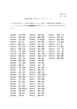
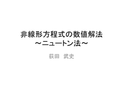
Figure 13: SPR curve for SF10(n = 1.723)|gold(50nm, ñ1 = 0.1726+i3.4218) |air(n =
1.0) for He-Ne laser light (633 nm).
The FORTRAN program to get the SPR curve by Eq.(211) is
c234567-- spr_angle_3layer.f --c
complex calculation
implicit real*8 (a-h,o-z)
complex*16 e1,rpr1,r12,rpr12,rpr12c,alpha,ref
complex*16 aaa,fukso,e2
c
c
c
c=2.99792458d8
hbar=6.5822d-16
pi=acos(-1.0d0)
------ air ---e2=dcmplx(1.0d0,0.0d0)
----- SF10 633 nm
enpr=1.723d0
----- gold 633 nm
e1n=0.1726d0
23
c
e1k=3.4218d0
e1r=e1n**2-e1k**2
e1i=2.0d0*e1n*e1k
e1=dcmplx(e1r,e1i)
---- gold thickness (m)
d1=50.0d-9
c
c
ramd=633.0d-9
omega=2.0d0*pi/ramd*c
fukso=dcmplx(0.0d0,1.0d0)
write (6,*) ramd,omega,hbar*omega
--------- angle scan ---------ang0=35.0d0
ang1=45.0d0
do i=1, 1001
theta=(ang0+dble(i-1)/1000.0d0*(ang1-ang0))/180.0d0*pi
rpr1=(cos(theta)/enpr &
sqrt(e1-enpr**2*sin(theta)**2)/e1)
&
/ (cos(theta)/enpr +
&
sqrt(e1-enpr**2*sin(theta)**2)/e1)
&
&
&
r12=( sqrt(e1-enpr**2*sin(theta)**2)/e1 sqrt(e2-enpr**2*sin(theta)**2)/e2 )
/ ( sqrt(e1-enpr**2*sin(theta)**2)/e1 +
sqrt(e2-enpr**2*sin(theta)**2)/e2 )
aaa=2.0d0*omega/c*d1*sqrt(e1-enpr**2*sin(theta)**2)
alpha=aaa*fukso
rpr12=(rpr1+ r12*exp(alpha))/(1.0d0+rpr1*r12*exp(alpha))
rpr12c=conjg(rpr12)
ref=rpr12*rpr12c
write (6,*) theta/pi*180.0d0,dble(ref)
enddo
end
The calculated results are shown in Fig. 12. At resonance or R = 0 the power of the
SPs is lost by internal absorption in the metal. This loss is compensated by the power
of the incoming light. Both have to be equal in the steady state.
If the reflectivity R has lowest value, the intensity of the electromagnetic field reaches
its maximum at the metal surface. For 600 nm light the maximum enhancement
of the electric field intensity is ca. 200 for silver film (60 nm thickness), 30 for gold
film, 40 for aluminum film, and 7 for copper film, respectively[1].
5.2
General solution of N-layer model. [ F. Abelès, Ann. Phys. (Paris)
5, (1950) 596. W. N. Hansen, J. Opt. Soc. Amer. 58 (1968) 380. ]
The tangential fields at the first boundary z = z1 = 0 are related to those at the final
boundary z = zN −1 by
"
U1
V1
#
"
= M2 M3 ...MN −1
24
UN −1
VN −1
#
"
=M
UN −1
VN −1
#
(219)
z1
1
z3 …
z2
2
zN-2 zN-1
3 4 … N-2 N-1 N
Figure 14: N-layer model for SPR measurement.
For p-wave at boundary k,
and
"
Mk =
Uk = HyT + HyR
(220)
Vk = ExT + ExR
(221)
cos βk
−i sin βk /qk
−iqk sin βk
cos βk
#
Here qk = (µk /ϵ˜k )1/2 cos θk
µk ∼
= 1
(222)
(223)
(ϵ˜k − n21 sin2 θ1 )1/2
(224)
qk ∼
= (1/ϵ˜k )1/2 cos θk =
ϵ̃k
2π
2π
βk =
ñk cos θk (zk − zk−1 ) = (zk − zk−1 ) (ϵ̃k − n21 sin2 θ1 )1/2 (225)
λ0
λ0
The reflection and transmission coefficient for p-wave (TM) is
rp =
Mij
=
(M11 + M12 qN )q1 − (M21 + M22 qN )
(M11 + M12 qN )q1 + (M21 + M22 qN )
ÃN −1
Y
!
,
Mk
k=2
i, j = 1, 2
Rp = |rp |
(228)
r
Rp1/2 eiφp
p
(229)
φrp
= arg(r )
tpH
2q1
(M11 + M12 qN )q1 + (M21 + M22 qN )
µN n1 p
=
t
µ1 ñN H
µN Re(ñN cos θN /ñ2N ) p 2
|tH |
=
µ1 n1 cos θ1 /n21
= arg(tpE )
tpE
Tp
φtp
(227)
ij
2
rp =
(226)
(230)
=
(231)
(232)
(233)
(234)
For s-wave (TE) the above equations hold except
s
qk =
ϵ˜k
cos θk
µk
In this sense these equations are easy to calculate the multilayer optical problem.
25
(235)
1
0.9
0.8
reflectance
0.7
0.6
(I) Au
0.5
0.4
(II) SAM on Au
0.3
0.2
0.1
0
35
36
37
38 39 40 41 42
incident angle (degree)
43
44
45
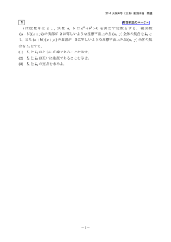
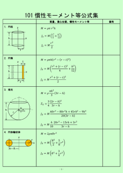
Figure 15: SPR curves for (I) the SF10 glass prism(n=1.723)|Au(n + ik =
0.1726+i3.4218, 50nm)|Air(n=1.0) and (II) the SF10 prism|Au(50nm)|SAM(n=1.61245,
1nm)|Air systems.
The SPR resonance calculation FORTRAN program for N-layer system is given
in the following, and the results for the 4-layer system [ prism|gold|Self-AssmbledMonolayer(SAM, 1 nm thickness)|Air ] is shown in Fig. 14. The SAM film thickness
of 1 nm is clearly seen as the shift of the SPR angle.
c234567-- spr_angle_Nlayer.f --c
1 | 2 | 3 ... N-2|N-1|N :N layer system
c
complex calculation
implicit real*8 (a-h,o-z)
parameter (nlay=10)
complex*16 e(nlay) , em(nlay,2,2) ,emtot(2,2)
complex*16 emtot1(2,2)
dimension en(nlay), ek(nlay), d(nlay)
complex*16 beta,q,rp,q1,qn,ref,tp,tra
complex*16 fukso
c
c
c=2.99792458d8
hbar=6.5822d-16
pi=acos(-1.0d0)
------- N layer ---nlayer=4
------ air ---en(4)=1.d0
ek(4)=0.0d0
26
field enhancement
25
20
15
10
5
35
36
37
38
39
40
41
42
Figure
16:
Field
enhancement
factor
|tph |2
prism|Au(50nm)|SAM(n=1.61245, 1nm)|Air system.
c
c
c
c
c
43
incident angle (degree)
er=en(4)**2-ek(4)**2
ei=2.0d0*en(4)*ek(4)
e(4)=dcmplx(er,ei)
----- SF10 633 nm
en(1)=1.723d0
ek(1)=0.0d0
er=en(1)**2-ek(1)**2
ei=2.0d0*en(1)*ek(1)
e(1)=dcmplx(er,ei)
----- gold 633 nm
en(2)=0.1726d0
ek(2)=3.4218d0
er=en(2)**2-ek(2)**2
ei=2.0d0*en(2)*ek(2)
e(2)=dcmplx(er,ei)
---- gold thickness (m)
d(2)=50.0d-9
------ SAM ----------en(3)=1.61245
ek(3)=0.0d0
er=en(3)**2-ek(3)**2
ei=2.0d0*en(3)*ek(3)
e(3)=dcmplx(er,ei)
----- SAM thickness --d(3)=1.0d-9
c
ramd=633.0d-9
omega=2.0d0*pi/ramd*c
fukso=dcmplx(0.0d0,1.0d0)
write (6,*) ramd,omega,hbar*omega
27
for
44
the
45
the
SF10
c
--------- angle scan ---------ang0=35.0d0
ang1=45.0d0
do i=1, 1001
theta=(ang0+dble(i-1)/1000.0d0*(ang1-ang0))/180.0d0*pi
q1=sqrt(e(1)-en(1)**2*sin(theta)**2)/e(1)
qn=sqrt(e(nlayer)-en(1)**2*sin(theta)**2)/e(nlayer)
do j=2, nlayer-1
beta=d(j)*2.0d0*pi/ramd*sqrt(e(j)-en(1)**2*sin(theta)**2)
q=sqrt(e(j)-en(1)**2*sin(theta)**2)/e(j)
em(j,1,1)=cos(beta)
em(j,1,2)=-fukso*sin(beta)/q
em(j,2,1)=-fukso*sin(beta)*q
em(j,2,2)=cos(beta)
enddo
emtot(1,1)=dcmplx(1.0d0,0.0d0)
emtot(2,2)=dcmplx(1.0d0,0.0d0)
emtot(1,2)=dcmplx(0.0d0,0.0d0)
emtot(2,1)=dcmplx(0.0d0,0.0d0)
do j=2, nlayer-1
emtot1(1,1)=em(j,1,1)
emtot1(1,2)=em(j,1,2)
emtot1(2,1)=em(j,2,1)
emtot1(2,2)=em(j,2,2)
emtot=matmul(emtot,emtot1)
enddo
&
&
&
&
&
&
&
&
c
rp=( (emtot(1,1)+emtot(1,2)*qn)*q1 (emtot(2,1)+emtot(2,2)*qn) )
/ ( (emtot(1,1)+emtot(1,2)*qn)*q1 +
(emtot(2,1)+emtot(2,2)*qn) )
tp=2.0d0*q1/( (emtot(1,1)+emtot(1,2)*qn)*q1 +
(emtot(2,1)+emtot(2,2)*qn) )
rp=( (emtot(1,1)+emtot(1,2)*qn)*q1 (emtot(2,1)+emtot(2,2)*qn) )
/ ( (emtot(1,1)+emtot(1,2)*qn)*q1 +
(emtot(2,1)+emtot(2,2)*qn) )
tp=2.0d0*q1/( (emtot(1,1)+emtot(1,2)*qn)*q1 +
(emtot(2,1)+emtot(2,2)*qn) )
ref=rp*conjg(rp)
enh=tp*conjg(tp)
tra=tp*conjg(tp)/cos(theta)*en(1)*dble(qn)
write (6,*) theta/pi*180.0d0,dble(ref),enh
write (6,*) theta/pi*180.0d0,dble(ref),dble(tra)
enddo
end
28
6
Acknowledgement
The author would like to thank for Mr. A. Shirakami for his great contribution to the
startup of the SPR study in our laboratory. The author also thank Prof. R. Corn, Prof.
T. Kakiuchi and Dr. D. Hobora for helpful discussions on this subject.
7
Appendix
In Fig.16 the phase shifts of the reflected wave(He-Ne laser light) are shown in the case
of Air(n = 1) →Water(n = 1.332)(top figure) and Water→Air(bottom figure). For the
case of Water→Air the critical angle for total reflection is 48.66 degree and the phase
shift is shown in Fig.6.
References
[1] H. Raether. Surface Plasmons on Smooth and Rough Surface and on Gratings. SpringerVerlag, Berlin, 1988.
[2] R. H. Ritchie. Plasma losses by fast electrons in thin films. Phys. Rev., 106:874–881, 1957.
[3] R. W. Wood. On a remarkable case of uneven distribution of light in a diffraction grating
spectrum. Phil. Mag. Ser. 6, 4:396–402, 1902.
[4] A. Otto. Excitation of surface plasma waves in silver by the method of frustrated total
reflection. Z. Physik, 216:398–410, 1968.
[5] H. Raether E. Kretschmann. Radaitive decay of non-radiative surface plasmons excited by
light. Z. Naturforsch., 23A:2135–2136, 1968.
[6] J. G. Gordon II and J. D. Swalen. The effect of thin organic films on the surface plasma
resonace on gold. Opt. Commun., 22:374–376, 1977.
[7] C. Nylander B. Liedberg and I. Lundstrom. Surface plasmon resonance for gas and biosensing. Sensers and Acutuators, 4:299–304, 1983.
[8] B. L. Frey R. Corn D. G. Hanken, C. E. Jordan. Surface plasmon reasonance measurements
of ultrathin organic films at electrode surfaces. Electroanal. Chem., 20:141–225, 1998.
[9] W. Knoll. Interfaces and thin films as seen by bound electromagnetic waves. Annu. Rev.
Phys. Chem., 49:569–638, 2000.
[10] R. Corn J. M. Brockman, B. P. Nelson. Surface plasmon reasonance imaging measurements
of ultrathin organic films. Annu. Rev. Phys. Chem., 51:41–63, 2000.
[11] D. M. Kolb. The study of solid-liquid interfaces by surface plasmon polariton excitation.
In V. M. Agranvich and D. L. Mills, editors, Surface Polaritons, chapter 8, pages 299–329.
North-Holland, Amsterdam, 1982.
[12] V. Scheumann Z. Zizlsperger J. Mack G. Jung A. Badia, S. Arnold and W. Knoll. Probing
the elecrochemical deposition and/or desorption of self-assembled and electropolymerizable
organic thin film by surface plasmon spectroscopy and atomic force microscopy. Sensors
and Actuators B, 54:145–165, 1999.
[13] M. Born and E. Wolf. Principles of Optics (7th expanded edition). Cambridge University
Press, Cambridge, 1999.
[14] E. Hecht. Optics. Addison-Wesley, San Francisco, 2002.
[15] S. Herminghaus M. Riedel P. Leiderer U. Weiland K.-F. Giebel, C. Bechinger and M. Bastmeyer. Imaging of cell/substrate contacs of living cells with surface plasmon resonance
microscopy. BioPhys. J., 76:509–516, 1999.
[16] C. Kittel. Introduction to Solid State Physics (7th edition). Wiley, New York, 1996.
29
180
rs
phase shift (degree)
150
120
90
air to water
rp
60
30
0
0
10
20
30
40
50
60
incident angle (degree)
70
80
90
180
150
phase shift (degree)
water to air
120
rp
90
60
30
rs
0
0
10
20
30
incident angle (dgree)
40
Figure 17: Phase shifts of the reflected wave(He-Ne laser light) are shown in the case
of Air(n = 1) →Water(n = 1.332)(top figure) and Water→Air(bottom figure). For the
case of Water→Air the critical angle for total reflection is 48.66 degree and the phase
shift is shown in Fig.6.
In Fig.17 schematic diagram of light reflection from black film is shown. When the
incident angle is small, the phase shift of s wave is π for OC and zero for OAB and the
phase shift of p wave is zero for OC and π for OAB.(Please see Fig.16) If the film
thickness d is much smaller than the wavelength/4, the interference between OC and
wave from B become destructive.(Please note that the formulation is shown in the inset
of Fig.17). Then we can see no light from thin film like lipid bilayer or soap bubble.
30
Figure 18: Schematic diagram of light reflection for black film. When the incident angle
is small, the phase shift of s wave is π for OC and zero for OAB and the phase shift of
p wave is zero for OC and π for OAB.(Please see Fig.16) If the film thickness d is much
smaller than the wavelength/4, the interference between OC and wave from B become
destructive. Please note that the formulation is shown in the inset. Then we can see no
light from thin film like lipid bilayer or soap bubble.
31
Appendix
Home-made SPR Apparatus (by A. Shirakami)
He-Ne laser
628.3 nm
Beam splitter
ND filter
Rotating stage
Lens
ǰ
Polarizer
PC
Lens
Detector
Lens
Detector
2ǰ
A/D converter
Electrochemical Cell for SPR
SF-10 hemicylindrical
prism
Working electrode
Glass slide
Gold layer
Potentiostat
Reference
electrode
Counter electrode
Details of the Sample Setup
SF10 glass Prism
n matching oil
SF10 slide glass
MPS
Au film (50nm)
SAM
Figure 19:
32
© Copyright 2026 Paperzz