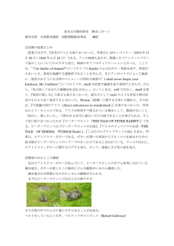
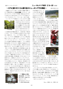
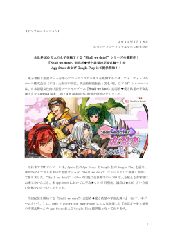
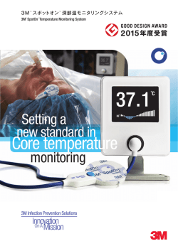
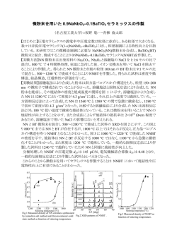
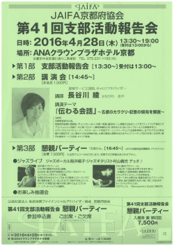
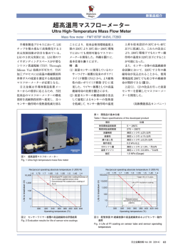
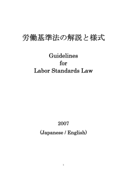
Reference Only
納入仕様書 SPECIFICATION
1/10
型名 TYPE
部品番号 Customer's Part No.
品番 Part No.
1.外観寸法
Physical Dimensions
HEAW
1155EA-0001=P3
推奨パターン図(参考)
Recommended PCB pattern(Reference)
10.5 MAX
(4.5)
(7.5)
(6.9)
(4.5)
(2 .8 )
(2.5)
(7.1)
(7.1)
4
3
(2)
2
LOT No.
13.0±0.3
1
0001
14.0±0.3
リード平坦性 Pin coplanarity
(0.4 MAX)
(3.2)
(0.1 MAX)
2±0.1
コイル上面平坦性 Flatness on top surface
一般寸法公差 ±0.3 単位 mm
Tolerance
Unit
1個当りの重量:6.0g(参考値)
Weight per piece
(Reference value)
ゲート位置 Gate position
ゲートの位置は部品の構造上、右下図のA~Dのいずれかの場所に1箇所存在します。
Gate position is subject to change due to molding die cavity.
The gate position will be either position A, B, C or D.
備考 Notes
RoHS Comp.
仕様書式 1155
C
D
B
A
Reference Only
2/10
HEAW
2.電気的性能 Electrical Characteristics
部品番号
Customer’s
part number
インダクタンス
Inductance
At100kHz,1V
部品番号
part number
1155EA-0001=P3
直流抵抗
DC resistance
定格電流
(インダクタンス
変化に基づく場
合)
Rated Current
Based on
Inductance
Change
Rated Current
Based on
Temperature
rise
定格電流
(温度上昇に
基づく場合)
中心値
許容差
L0(μH)
Tolerance
(m ohms)
(A) (Max.)
(A) (Max.)
10
±20%
25 max.
7.2 max.
3.0 max.
※上記の電気的性能規格は 25±10℃の保証となります。
The electrical characteristics specification above shall be achieved in 25±10℃.
3.接続図 Connection
S 1
2
4
3 S
(上面図 Top view)
S : スタート
Start of winding
4.測定条件 Measurement conditions
「特に指定が無い限り、測定は常温(温度 5~35℃)、常湿(湿度 45~85%)、常気圧(気圧 86~106kPa)にて
行う。ただし、判定に疑義を生じた場合は温度 20±2℃、湿度 65±5%、気圧 86~106kPa にて行う。」
Unless otherwise specified, the standard range of atmospheric conditions in making measurements
and test as follows;
Ambient temperature : 5℃ to 35℃ , Relative humidity : 45% to 85% ,
Air pressure : 86kPa to 106kPa
If more strict measurement is required, measurement shall be made within following limits;
Ambient temperature : 20±2℃ , Relative humidity : 65±5% ,
Air pressure : 86kPa to 106kPa
1)定格電流(インダクタンスに基づく場合) Rated Current (Based on Inductance Change)
定格電流(インダクタンスに基づく場合)とは、インダクタンスの値が初期値より 25%減少する直流電流値。
(1-4 端子をショートし各巻線を直列接続させ 2-3 端子間に直流電流を印加する。)
The DC saturation allowable current value is specified when the initial inductance value at 25%.
(The DC current entry point is between pin 2 and 3. Pin 1 and 4 are connected during measurement.)
2)定格電流(温度上昇に基づく場合) Rated Current (Based on Temperature rise)
定格電流(温度上昇に基づく場合)とは、コイルの温度が 40℃上昇する値とする。
(1-4 端子をショートし各巻線を直列接続させ 2-3 端子間に直流電流を印加する。)
Rated Current (Based on Temperature rise) is specified when temperature of the inductor raised
40℃ by DC current.
(The DC current entry point is between pin 2 and 3. Pin 1 and 4 are connected during measurement.)
3)インダクタンス値及び直流抵抗値は 1-2 端子間または 3-4 端子間とする。
The inductance and DC resistance specification are based on the measurement between pin 1 and 2 or pin 3
and 4.
Reference Only
5.耐候的性能 Reliability Specifications
P.3 ~ P.5 参照 See page 3 to 5.
仕様書式 1155
3/10
Reference Only
4/10
HEAW
項目 Item
規格 Spec.
条件 Conditions
前処理条件:85℃/85% 168 時間放置後、リフロー2回
Pre-Treatment : 85℃/85% 168hours, Reflow 2times
高温試験
High Temperature
Exposure
⊿L/L < ±3%
125±2℃にて 1000±12 時間放置した後に、常温常湿中に 24±2 時間
放置し測定する。
Samples shall be subjected to 125±2℃ for 1000 hours.
Measure after 24 ± 2 hours exposure at room temperature and
humidity.
前処理条件:85℃/85% 168 時間放置後、リフロー2回
Pre-Treatment : 85℃/85% 168hours, Reflow 2times
温度サイクル試験
Temperature Cycling
⊿L/L < ±3%
-40±3℃にて 30 分、125±2℃にて 30 分、それぞれの温度への移行
時間を 2 分以下とし、1000 サイクル行った後、室温に 24±2 時間放置し
測定する。
Lower strage temperature : -40±3℃
Upper strage temperature : 125±2℃
Dwell time : Each 30 min. Transfer time ≤ 2 min.
Number of cycles : 1000
Measure after 24±2 hours exposure at room temperature and humidity.
前処理条件:85℃/85% 168 時間放置後、リフロー2回
Pre-Treatment : 85℃/85% 168hours, Reflow 2times
耐湿サイクル試験
Moisture Resistance
⊿L/L < ±3%
試験条件は、MIL-STD-202 Method 106 に準ずる。
Test Method : Base on MIL-STD-202 Method 106
ただし t = 24 hours/cycle としステップ 7a 及び 7b は含まず試験を行う。
試験後室温に 24±2 時間放置し測定する。
t = 24 hours/cycle. Note: Steps 7a & 7b not included with the test.
Measurement at 24±2 hours after test conclusion.
前処理条件:85℃/85% 168 時間放置後、リフロー2回
Pre-Treatment : 85℃/85% 168hours, Reflow 2times
高温高湿試験
Biased Humidity
⊿L/L < ±3%
85±2℃/85±5%にて 1000±12 時間放置した後に、常温常湿中に 24±
2 時間放置し測定する。
Samples shall be subjected to 85±2℃/85±5% for 1000 hours.
Measure after 24 ± 2 hours exposure at room temperature and
humidity.
前処理条件:85℃/85% 168 時間放置後、リフロー2回
Pre-Treatment : 85℃/85% 168hours, Reflow 2times
高温動作試験
Operation life
⊿L/L < ±3%
耐薬品性試験
Resistance to Solvent
捺印が消失せず
判別可能な事。
Marking should
not disappear
and can read.
仕様書式 1155
85±2℃にて定格電流を通電し 1000±12 時間放置した後に、常温常湿
中に 24±2 時間放置し測定する。
Applied load:Rated current, 85±2℃ for 1000 hours.
Measure after 24±2 hours exposure at room temperature and humidity.
試験基板に実装後、IPA 溶液中に 3 +0.5/-0 分間浸す。
After mounted on PCB, Immersion IPA 3 +0.5/-0 minutes.
Reference Only
5/10
HEAW
項目 Item
衝撃試験
Mechanical Shock
振動試験
Vibration
はんだ耐熱性試験
Resistance to
Soldering Heat
規格 Spec.
条件 Conditions
⊿L/L < ±3%
衝撃の大きさ:100G、衝撃波の時間:6ms、衝撃波形:ハーフサイン
互いに垂直な 6 方向に各3回(計 18 回)加える。
Peak value : 100G, Nomal duration : 6ms, Wave form : Half-sine.
Three shocks in each direction shall be applied along the three
mutually perpendicular axes of the test specimen (18 shocks).
(MIL-STD-202 Method 213 Test condition ‘C’.)
⊿L/L < ±3%
振動周波数:10~2000Hz 加速度:5G
掃引:10~2000~10Hz/20 分 12 サイクルを3方向で実施。
5g's for 20 minutes, 12 cycles each of 3 orientations.
Test from 10-2000 Hz.
⊿L/L < ±3%
プリヒート:183℃以上 90~120 秒
本加熱:250±5℃ 30±5 秒間
常温に戻す。
以上を3回繰り返す。
Pre-heat : 183℃ or more. 90 to 120sec.
Test temperature : 250±5℃. 30±5sec.
The assembly shall then be allowed to cool to room ambient
temperature.
This constitutes one heat cycle. The assembly shall be exposed to
three heat cycles.
(MIL-STD-202 Method 210 Test condition ‘K’.)
前処理条件:85℃/85% 168 時間放置後、リフロー2回
Pre-Treatment : 85℃/85% 168hours, Reflow 2times
熱衝撃試験
Thermal Shock
⊿L/L < ±3%
静電試験
ESD
⊿L/L < ±3%
はんだ付け性試験
Solderability
端子のはんだ付け
面の95%以上が
覆われる事。
Solder covered
surface shall
be more than 95%.
仕様書式 1155
-40±3℃にて 15 分、125±2℃にて 15 分、それぞれの温度への移
行時間を 20 秒以内とし、300 サイクル行った後、室温に 1~2 時間放
置し測定する。
Lower strage temperature : -40±3℃
Upper strage temperature : 125±2℃
Dwell time : Each 15 min. Transfer time ≤ 20 sec.
Number of cycles : 300
Measure after 1 to 2 hours exposure at room temperature and
humidity.
AEC-Q200 method 002 rev.C
Rd = 2000Ω、Cd = 150pF、Direct contact.
245±5℃のはんだ槽に供試体を 4±0.5 秒間浸す。
Dip sample into solder bath containing molten
solder at 245±5℃ for 4±0.5 seconds.
(Evaluation used solder:Sn3.0Ag0.5Cu)
Reference Only
6/10
HEAW
項目 Item
規格 Spec.
基板たわみ性試験
Board Flex
外観検査を行い
破損なき事。
There shall be no
breakage
or loosening of
the terminals.
条件 Conditions
前処理条件:85℃/85% 168 時間放置後、リフロー2回
Pre-Treatment : 85℃/85% 168hours, Reflow 2times
基板たわみ 2mm、60±5 秒
Apply a force which will bend 2 mm.
The duration time is 60 (+ 5) Sec.
前処理条件:85℃/85% 168 時間放置後、リフロー2回
Pre-Treatment : 85℃/85% 168hours, Reflow 2times
端子固着強度試験
Terminal Strength
使用温度範囲
Operating
Temperature
保存温度範囲
Storage Temperature
仕様書式 1155
⊿L/L < ±3%
供試基板に実装された部品に側部から 17.7 N (1.8 Kgf)の力を 60 (+
1)秒間加える。
Apply a 17.7 N (1.8 Kgf) force to the side of a device.
The duration time is 60 (+ 1) Sec.
-40℃~85℃
-40℃~85℃
-40℃~60℃ (with Tape and Reel Packing)
Reference Only
7/10
テーピング仕様
TAPING SPECIFICATIONS
HEAW TYPE
【テープ寸法図・TAPE DETAILS】
(記事・Note)
1.装着テープの材質は、HI-PS とする。
Carrier tape material shall
be HI-PS.
2.シールテープの材質は
ポリエチレンおよび
ポリエチレンテレフタ
レートとする。
Fixing seal tape material
shall be Polyethylene or
Polyethylene Terephthalate.
3.シールテープは送り穴を
ふさいだり、装着テープ
からはみ出したりして
いないこととする。
Fixing seal tape shall
neither cover feed hole nor
bulge out of carrier tape.
4.シールテープ剥離強度
0.2~0.7N 以内
The range of the force to peel
away the fixing seal tape
shall be ;
Min. 0.2N , Max. 0.7N
【部品装着図・TAPING METHOD】
引出方向
Puling
direction
③
②
④
①
上面図
Top view
取付電極面
Electrode
仕様書式 1155
(記事・Note)
1.部品の挿入は取付け電極を
下面とする、また引き出し
方向は左図とする。
Electrode shall be packaged
in the tapes upside down
against fixing tape. Pulling
direction of tape refer to
引出方向
this picture.
Puling
2.部品装着部の前後には
direction
各々30 ピッチ以上の空部
を設ける。引き出し側には
空ポケットを含み 400 ㎜
以上のリーダ部を設ける。
30 pitches(no components)
minimum leaders shall be
provided at the beginning and
the end of each reel. 400mm
minimum leaders including no
component carrier tape shall
be provided at the end of each
reel.
Reference Only
テーピング仕様
TAPING SPECIFICATIONS
HEAW TYPE
【リール寸法図・REEL DETAILS】
φ
±2
330
【荷姿・PACKING CASE】
表示・Marking
仕様書式 1155
±1.0
φ
φ ±0.8
21
80
φ
13
+0.3
2 -0
±0.2
表示
MARKING
(記事・Note)
1.リールは EIAJ ETX-7001 に
準拠する。
Reel conform to EIAJ EXT-7001.
2.リール材質はポリスチレン
とする。
Reel material shall be
Polystyrene.
3.1リール当りの数量は
200 個入りとする。
Parts quantity per reel shall
be 200 pieces
(200 pcs. / 1 reel)
±0.5
4.リールには貴社部品番号、
33.5
±1.0
数量、ロット番号 を表示する。
37.5
Each reel shall be marked with
the following ;
Customer’s part number
Quantity
Lot No.
(記事・Note)
1.梱包箱の材質は紙とする。
Packing case material shall be
kraft paper.
2.梱包箱は 1 リール入りとする。
Reel quantity per packing case shall be
one (1) reel.
3.梱包箱には貴社部品番号、数量、ロット番号
を表示する。
Each packing case shall be marked with the
following ;
Customer’s part number
Quantity
Lot No.
8/10
Reference Only
注意事項 Notice
使用上の注意事項 Notice
1, 樹脂コーティング Resin coating
製品を樹脂で外装される場合、樹脂のキュアストレスが強いとインダクタンスが変化したり製品の性能に
影響を及ぼすことがありますので、樹脂の選択には十分ご注意下さい。また、実装された状態での信頼性評
価を実施下さい。
The inductance value may change and/or it may affect on the product's performance due to high
cure-stress of resin to be used for coating / molding products. So please pay your careful attention when
you select resin.
In prior to use, please make the reliability evaluation with the product mounted in your application set.
9/10
Reference Only
10/10
お願い Note
お願い
(1)ご使用に際しては、貴社製品に実装された状態で必ず評価して下さい。
(2)弊社は、仕様書、図面その他の技術資料には、取引に関する契約事項を記載することは適切ではないものと存じて
おります。従って、もし、貴社が作成されたこれら技術資料に、品質保証、PL、工業所有権等にかかる弊社の
責任の範囲に関する記載がある場合は、当該記載は無効とさせていただきます。
これらの事項につきましては、別途取引基本契約書等においてお申し越しいただきたくお願いします。
(3)記載内容について、改良のため予告なく変更することや供給を停止することがございますので、
ご注文に際してはご確認ください。
(4)当WEBサイトには、代表的な仕様しか記載しておりませんのでご注文にあたっては詳細な情報が記載されている
納入仕様書の内容をご確認いただくか承認図の取交しをお願いします。
Note
(1) Please make sure that your product has been evaluated in view of your specifications
with our product being mounted to your product.
(2) We consider it not appropriate to include any terms and conditions with regard to the business transaction in the product specifications,
drawings or other technical documents. Therefore, if your technical documents as above include such terms and conditions
such as warranty clause, product liability clause, or intellectual property infringement liability clause, they will be deemed to be invalid.
(3) It’s specifications are subject to change or our products in it may be discontinued without advance notice.
Please check with our sales representatives or product engineers before ordering.
(4) This website has only typical specifications because there is no space for detailed specifications.
Therefore, please review our product specifications or consult the approval sheet for product specifications before ordering.
© Copyright 2026 Paperzz