CAM CLUTCH BS SERIES
カムクラッチ BSシリーズ
BACKSTOP CAM CLUTCH
1
"A More Prosperous Tomorrow for Everyone".
∼より豊かな人間社会の実現∼
「ツバキエマソン」は、「新世紀のパワートランスミッショ
ン」をより発展させるために誕生しました。より一層の高
度化・精密化そしてエレクトロニクス化が求められている
パワートランスミッション。
私たちは従来より、メカトロニクスの分野において積極的
に事業を展開し、その商品は国内外のお客様から絶大な評
価と信頼をいただいてまいりました。
「ツバキエマソン」
はメカトロニクス化を高度に推進することで、産業から暮
らしまでのさまざまなシーンに貢献、『より豊かな人間社
会の実現』に寄与する企業を目指します。
TSUBAKI EMERSON was created to develop the new
century's power transmission products.
The power transmission field now calls for even more
sophisticated and precision application products, and
we plan to help meet those demands.
Our customers throughout the world rely upon our
products and highly regard them as the best available in
the industry.
TSUBAKI EMERSON contributes to various areas, not
only industry, but also society, through our promotion of
Mechatronics. We aim to be a company that contributes
to "A more prosperous tomorrow for everyone".
お客様と共に歩む魅力ある工場の創造
Creating an effective manufacturing facility that
evolves along with our customers
TSUBAKI EMERSON is based at our Kyoto Plant (Head
office), and includes our Hyogo and Okayama plants.
「ツバキエマソン」は京都工場(本社)をベースとし、兵
庫工場、岡山工場にて製造を展開しております。
We started to sell the BS series Cam Clutches in 1969.
The BS series was developed for conveyors and bucket
elevators to prevent reverse rotation.
To meet higher speed and torque demand, we
developed and completed the BS-HS series in 2005.
We have been selling the BS & BS-HS series not only in
Japan but also all over the world.
Tsubaki offers a complete line of "BS series" with HIGH
TORQUE CAPACITY, INSTANTANEOUS HOLD BACK,
SOUNDLESS OPERATION, EASY MAINTENANCE,
LONG SERVICE LIFE and COMPACTNESS to meet all
the requirements of design engineers and maintenance
people.
1969年よりBSシリーズをコンベヤ、バケットエレベータ
の逆転防止専用クラッチとして販売を開始し、2005年には
高速、高トルクを実現させたBS-HSシリーズを加わえ、国
内に留まらず海外へも代理店を通じ、長年に渡り実績を積
上げてまいりました。
「ツバキエマソン」は高許容トルク、確実な逆転防止、静音、
簡単なメンテナンス、長寿命、コンパクト化を追求するエ
ンジニア、保全関係のあらゆる必要性に見合った“BSシ
リーズ”を提供いたします。
Visit TSUBAKI EMERSON on the Web:
ツバキエマソンホームページ
http://www.tsubaki-emerson.co.jp/
Table of Contents
目 次
About us ……………………………………………… 1-2
Design features ……………………………………… 3-8
BS & BS-HS series …………………………………… 9-13
BS-R series ………………………………………… 14-18
How to Order (Oil Reservoir Type) ……………………… 19
Torque Arm for BS series ………………………… 20-21
Safety Cover for BS series ……………………………… 22
BSEU series ………………………………………… 23-24
Lubrication and Maintenance ……………………… 25-26
Typical applications ……………………………………… 27
Special design versions available ……………………… 28
Selection procedures ……………………………… 29-30
Keyway dimensions………………………………… 31-32
Service life of Cam Clutch ………………………… 33-34
Application form for BS series selection ……………… 35
会社紹介 …………………………………………………… 1-2
デザインの特長 …………………………………………… 3-8
BS & BS-HS シリーズ …………………………………… 9-13
BS-R シリーズ ………………………………………… 14-18
注文方法(オイルリザーバタイプ)………………………… 19
BS シリーズ用トルクアーム ………………………… 20-21
BS シリーズ用安全カバー ………………………………… 22
BSEU シリーズ ………………………………………… 23-24
潤滑とメンテナンス …………………………………… 25-26
アプリケーション例 ………………………………………… 27
特別仕様 ……………………………………………………… 28
選定方法 ………………………………………………… 29-30
キー溝寸法 ……………………………………………… 31-32
カムクラッチの寿命 …………………………………… 33-34
BSシリーズ選定用紙 ………………………………………… 35
2
CAMS AND CONSTRUCTIONS
カムと構造
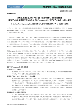
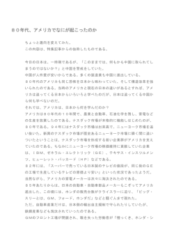
Cams for Backstop Cam Clutch (Non-roll over cam) General Cam
バックストップカムクラッチ用カム(ノンロールオーバカム) 一般用カム
Cam & Roller Construction for small size/小型BSカムクラッチのカム&ローラ構造
Roller/ローラ
Outer race/外輪
Cam/カム
Inner race/内輪
BS30∼BS75
Spring/スプリング
Cam & Roller Cage Construction for middle size/中型BSカムクラッチのカム&ローラ構造
Outer race/外輪
Cam/カム
Roller/ローラ
Spring/スプリング
Inner race/内輪
Cage-ring/ケージリング
BS85∼BS135
3
CAMS AND CONSTRUCTIONS
カムと構造
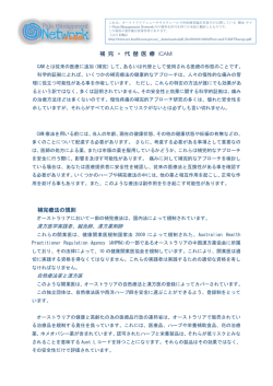
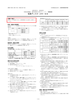
Cam only Construction for large size/大型BS-HSシリーズの構造
BS160HS∼BS450HS
Cam/カム
Outer race/外輪
O-ring
Seal supporter
O-リング
シールサポ
Bearing (Roller cage)
ベアリング
Inner race/内輪
Cage-ring/ケージリング
Grease fitting
(Dust protective
plate)
グリスキリ
Spring/スプリング
Cam cage
カムケージ
Double lip oil
seal
ダブルリップ
オイルシール
Cams and their constructions
カムと構造
The BS series Cam Clutches use non-rollover cams
(cams which do not flip) with a profile that is most suited
for the backstopping function, placing importance on
the load distribution among the cams which themselves
have many cross sections. Even if an unexpectedly
large reverse torque occurs following an appropriate
selection, the clutches will not roll over, preventing the
conveyor from reversing.
BSシリーズ カムクラッチには、多くの断面形状をもった
カムの中から、耐荷重性が重視される逆転防止機能に最も
適した形状のノンロールオーバ カム(反転破壊されない
カム)が採用されています。
適切な選定下における想定外の大きな逆転トルクが作用し
た場合でも、ロールオーバされることなくコンベヤの逆転
を防止することができます。
小型BSカムクラッチはカムとローラを交互に配列した構
造を採用し、ローラがベアリングの役目をして内外輪の同
心性を保つように設計されています。
Small size BS Cam Clutches use a structure where
cams and rollers are arranged alternately, and rollers act
as a bearing to maintain the concentricity of the inner
and outer races.
中型BSカムクラッチはカム&ローラケージ構造を採用し、
ローラがベアリングの役目を果します。さらにカム&ロー
ラケージならではの3つの特長を兼備えています。(詳し
くは6∼8ページを参照ください。)
Medium size BS Cam Clutches use a cam and roller
cage structure where rollers act as the bearing. In
addition, they have their very own special 3-feature of
cam and roller cage structure.
(Refer to pages 6-8 for details.)
大型BS-HSカムクラッチはノンロールオーバ カムケージ
と、両サイドをベアリングでサポートする構造を採用し、
より高い回転数での使用が可能であるばかりでなく、トル
ク容量も大幅にアップして、大型のコンベヤがより安全に
運転できるように改良されています。
Large size BS-HS series Cam Clutches use a nonrollover cam cage and structure to support both sides
with bearings, making it possible to use at a higher
overrunning speed. Additionally, torque capacity has
significantly increased, and the large conveyor can be
operated much more safely.
いずれのサイズも、特殊なオイルシール(BS30∼BS135)と、
ダブルリップ オイルシール、Oリング、グリスキリのコン
ビネーション(BS160HS∼BS450HS、BS160∼BS450)に
より、微細な粉塵の浸入を防止します。
All sizes have a dust free system which prevents fine
dust from entering the Cam Clutch. (BS30 to BS135:
Special oil seal. BS160HS to BS450HS, BS160 to
BS450: Double lip oil seal, o-ring and grease fitting.)
4
PRINCIPLES OF MOTION
作動原理
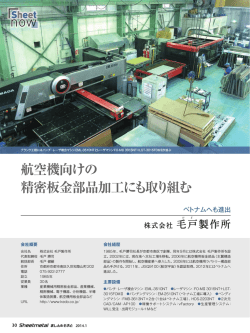
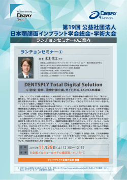
Operating principles
O’
The outer race's rotation is stopped by the torque arm.
Cams contact with the inner and outer races at points A
and B respectively. AB maintains a constant
engagement angle (strut angleθ) with the center line
O-O'. The strut angle is an integral part of the
overrunning and engagement function of the BS Cam
Clutch.
Springs give the rotational moment of F to cams
ensuring precise contact is maintained between the
inner and outer races.
When the inner race (conveyor shaft) rotates in the
direction of the black arrow , the inner race overruns
smoothly because AB does not act as a strut. At this
time, cams maintain light contact due to the spring
force.
When the conveyor stops and the inner race (conveyor
shaft) rotates in the direction of the white arrow ⇨, the
inner race is locked immediately by the cams because
AB acts as a strut, and prevents the conveyor from
rotating in reverse.
Outer race
外輪
A
Cam
F
Spring
カム
スプリング
B
Inner race
内輪
nning
Engage
Overru
かみ合
ment
い
空転
Strut angle(θ)
O
ストラットアングル(θ)
F
F
Cam
作動原理
カム
外輪はトルクアームによってその回転が止められていま
す。そしてカムは内外輪と点A・Bで接しています。ABは
内外輪の中心線O−O'と一定のかみ合い角度(ストラット
アングルθ)を保っています。
ストラットアングルは、カムクラッチに“空転”と“かみ
合い”の機能を与える重要な役目を果たしています。
スプリングはカムに対してFの回転モーメントを与えて、
カムを内外輪に軽く接触させています。
の方向に回るとABはつっ
内輪(コンベヤ軸)が黒矢印
かい棒として作用しない方向になるために、内輪はスムー
ズに空転します。この時カムはスプリング力によって軽い
接触状態を保っています。
コンベヤが停止して内輪(コンベヤ軸)が白矢印 ⇨ の方
向に回転しようとすると、つっかい棒が作用する方向にな
るために、内輪はカムによって即座にロック状態になり、
コンベヤの逆転を防止します。
Spring
スプリング
Outer race
O'
外輪
A
Spring
スプリング
F
B
Strut angle(θ)
Inner race
内輪
O
ストラットアングル(θ)
Overrunning
Engagement
空転
かみ合い
5
SELF LUBRICATION AND REDUCE THE SPEED
自己潤滑と滑り速度低減
Cam/カム
Roller/ローラ
Outer race/外輪
Overrunning/空転
Inner race/内輪
V2
Roller/ローラ
V1
Cam/カム
1. Self lubrication function
1.自己潤滑機能
When the Inner race overruns, rollers also rotate so the
cam and roller cage orbit around the inner race outer
circumference at low speed. Grease in the cam and
roller cage spreads completely throughout the insides of
the Cam Clutch due to the orbital motion, thus
maintaining good lubrication.
内輪が空転するとローラは回転させられます。その結果、
カム&ローラケージは内輪の外周を低速で公転します。カ
ム&ローラケージ内に封入されたグリースは、その公転運
動によりカムクラッチ内部全周に運ばれ、常に良好な潤滑
状態を保ちます。
2. Sliding speed diminishing function
2.滑り速度低減機能
The actual sliding speed of the cams and the inner race
is reduced due to the orbital motion of the cam and
roller cage, so the wear on the cams is diminished, and
a longer overrunning wear is possible.
カム&ローラケージの公転運動によって、カムと内輪の実
際の滑り速度は低減されます。その結果、カムの摩耗も軽
減され長い空転摩耗寿命が得られます。
V = V1 − V2
V : Sliding speed of cams and inner race
V1: Rotational speed of inner race
V2: Orbital speed of cam and roller cage
V = V1 − V2
V :カムと内輪の滑り速度
V1:内輪の回転速度
V2:カム&ローラケージの公転速度
6
DISPLACEMENT OF CONTACT POINT FUNCTION
Outer race
カム接点移動機能
TEM
外輪
Slightly narrow
わずかに狭い
TEM
Inner race
内輪
Different inclination
異なる傾き
わずかに広い
TEM
Slightly wide
TEM
Displacement of contact point function
カム接点移動機能
Rollers function as bearings and orbit while rotating on
their axis, and supporting the outer race. There is a
slight clearance between the rollers, the inner and outer
races; therefore the bottom of the cam space between
the inner and outer races is slightly wider compared
with the top. Cams always maintain contact by spring
force, and the slant of the cams is automatically different
at the top and the bottom.
Cams continuously orbit by changing the contact point
with the inner and outer races; therefore the wear on
cams due to overrunning is diminished to the minimum,
and the overrunning wear life on the Cam Clutch is at
the maximum length.
For the conveyor which is always in an overrunning
condition during the operation, as well as the self
lubrication function and the sliding speed diminishing
function, it is the one of the major features of a cam and
roller cage to realize a long operating life.
ローラはベアリングの役目をし、外輪をサポートして自転
しながら公転します。ローラと内外輪の間にはわずかなク
リアランスがあります。したがって内外輪間のカムスペー
スは、下部が上部に比べわずかに広くなっています。カム
はスプリング力によって常に軽い接触状態を保っているた
めに、上部と下部ではカムの傾きが自動的に異なります。
つまりカムは常に内外輪との接触位置を変えながら公転し
ています。その結果、空転によるカムの摩耗は軽減され、
カムクラッチの空転摩耗寿命は最大限に長くなります。
コンベヤが運転中、常に空転状態にあるクラッチにおいて
は、自己潤滑機能、滑り速度低減機能と共に長寿命を実現
するカム&ローラケージの大きな特長の一つです。
7
DIFFERENT SLIDING SPEED AND CONTACT FORCE
Cam Clutch/カムクラッチ
滑り速度と接触力
Roller Clutch/ローラクラッチ
Ps
Pc
F
Ps
V2
Do
Di
滑り速度と接触力による空転摩耗寿命の違い
Differences in an overrunning wear life by the
sliding speed and contact force
BSカムクラッチのカムは、前述の滑り速度低減機能によ
り、減速された滑り速度で内輪外周(Di )との間で摺動し
ています。このときのカムと内外輪の接触力はスプリング
力(Ps)のみにより与えられています。
ローラクラッチは、ローラが内輪と連結されたローラケー
ジに組み込まれているために、ローラは外輪の内周部(Do)
との間で滑りが発生します。
したがって、その滑り速度はカムと内輪の滑り速度に比べ
て速くなります。
そしてローラと外輪の接触力は、スプリング力(Ps)にロー
ラケージの回転により発生するローラの遠心力(Pc)も作
用するために、その接触力は非常に大きなものになります。
低い滑り速度と小さな接触力で空転しているBSカムク
ラッチはローラクラッチに比べ、非常に長い空転摩耗寿命
が得られます。
BS Cam Clutch cams slide on the outer circumference
of the inner race (Di ) at the decelerated sliding speed
due to the sliding speed diminishing function described
above. The contact force of cams and inner and outer
races are given only by spring force (Ps).
As for the Roller Clutches, rollers slide in the inner
circumference of the outer race (Do) because rollers are
built onto roller cage which is connected with the inner
race. Therefore the sliding speed of Roller Clutches is
faster when compared with that of the Cam Clutches
between the cams and inner race. In addition, the
contact force of rollers and the outer race is quite large
because the centrifugal force caused by the rotation of
the roller cage is added to the spring force (Ps).
The BS Cam Clutches overrun with low sliding speed
and low contact force, thus the BS Cam Clutches have
a long overrunning wear life when compared with the
Roller Clutches.
8
BS & BS-HS SERIES CAM CLUTCH
コンベヤの主軸に取付けられる、低速軸逆転防止専用の
カムクラッチです。
The BS series Cam Clutches are intended for
applications where reverse rotation of the slow speed
conveyor head shaft is to be prevented (backstopping).
■ MODELS BS30 TO BS135
For Reverse Rotation Prevention on Conveyors
BS30∼135
7
1
3 4
6
5
H-M
8
9
7
5
1
3 4
2
6
2
8
A
6
3
5
4
7
H-M
(both faces/両面等配)
1
A
H-M
A
C
B
E
B
E
D
E
D
B
C
C
D
2
S
S
H-M
(both faces/両面等配)
BS30 to BS50
①
②
③
④
⑤
⑥
⑦
⑧
BS65 to BS75
Inner race/内輪
Outer race/外輪
Cam/カム
Roller/ローラ
Plate/ソクバン
Spring/スプリング
Spirolox/スピロロックス
Oil seal/オイルシール
① Inner race/内輪
② Outer race/外輪
③ Cam/カム
④ Roller/ローラ
⑤ Spring/スプリング
⑥ Plate/ソクバン
⑦ Thrust metal/スラストメタル
⑧ Oil seal/オイルシール
⑨ Spirolox/スピロロックス
H-M
(both faces/両面等配)
BS85 to BS135
①
②
③
④
⑤
⑥
⑦
Inner race/内輪
Outer race/外輪
Cam cage/カムケージ
Plate/ソクバン
Thrust metal/スラストメタル
Spirolox/スピロロックス
Oil seal/オイルシール
Chamfer of the bore end faces
Chamfer
Shaft Diameter
1.5 C
Under 50 mm
2.0 C
50 to 125 mm
3.0 C
125 to 285 mm
軸穴端部の面取寸法
軸 径
50以下
50をこえ125 〃
125 〃 285 〃
面取り
C1.5
C2.0
C3.0
BS-HS SERIES CAM CLUTCH
空転回転速度および許容トルクを大幅にアップさせたHigh
Speed仕様です。
The BS-HS series offer higher torque and speed not
found in conventional models.
■ MODELS BS160HS TO BS450HS
BS160HS∼BS270HS
13
A
11
E
D
B
10
C
7 6 4 2
3 13
5
①
②
③
④
⑤
⑥
⑦
⑧
⑨
⑩
⑪
⑫
⑬
Inner race/内輪
Outer race/外輪
Cam cage/カムケージ
Seal supporter/シールサポ
Bearing/ベアリング
Oil seal/オイルシール
Grease fitting/グリスキリ
O-ring/O-リング
Snap ring/トメワ
Socket bolt/六角穴付きボルト
Seal washer/シールワッシャ
Set screw/穴付きトメネジ・クボミ
Air breather/エアブリーザ
①
②
③
④
⑤
⑥
⑦
⑧
⑨
⑩
⑪
⑫
⑬
⑭
Inner race/内輪
Outer race/外輪
Cam cage/カムケージ
Roller cage/ローラケージ
Seal supporter/シールサポ
Thrust bearing/スラスト軸受
Oil seal/オイルシール
Grease fitting/グリスキリ
O-ring/O-リング
Snap ring/トメワ
Socket bolt/六角穴付きボルト
Seal washer/シールワッシャ
Set screw/穴付きトメネジ・クボミ
Air breather/エアブリーザ
8 9 12 1
Lubricant filler/給脂プラグ
BS300HS∼BS350HS・BS425HS∼BS450HS
A
14
12
B
E
D
11
C
8
7 5 4
3 14
6 2 9 10 13 1
Lubricant filler/給脂プラグ
The double cam cage is used in BS425HS, BS450HS
BS425HS、BS450HSはダブルカムケージ構造となります。
9
BS & BS-HS SERIES CAM CLUTCH
Dimension and Capacities
伝動能力表および軸穴径
Model
BS
BS
BS
BS
BS
BS
BS
BS
BS
BS
BS
BS
BS
BS
BS
BS
BS
30
50
65
75
85
95
110
135
160HS
200HS
220HS
250HS
270HS
300HS
350HS
425HS
450HS
Dimensions in mm/単位:mm
T.C.
M.O.S. N.O.D.T.
(N・m) {kgf・m}
(r/m)
(N・m)
294 {
30}
350
0.588
784 {
80}
300
0.98
1,570 {
160}
340
3.92
2,450 {
250}
300
5.88
5,880 {
600}
300
7.84
7,840 {
800}
250
9.8
10,800 { 1,100}
250
14.7
15,700 { 1,600}
200
19.6
39,200 { 4,000}
350
34.3
61,700 { 6,300}
250
44.1
102,000 { 10,400}
200
73.5
147,000 { 15,000}
170
93.1
204,000 { 20,800}
160
98.0
294,000 { 30,000}
150
108.0
392,000 { 40,000}
110
157.0
735,000 { 75,000}
85
216.0
980,000 {100,000}
80
245.0
T.C.
M.O.S.
N.O.D.T.
T.H.S.×P−Q'ty
G.F.H.
Q. of G.
A
B
C
PCD:D
E
S
64
67
90
90
115
115
115
135
180
205
330
370
385
425
440
570
570
90
125
160
170
210
230
270
320
360
430
500
600
650
780
930
1,030
1,090
64
67
85
85
110
110
110
130
175
200
325
365
380
420
480
580
600
80
110
140
150
185
200
220
280
315
380
420
530
575
690
815
940
990
45
70
90
100
115
130
150
180
220
260
290
330
370
470
535
635
645
13
16
20
20
30
30
30
30
40
40
40
50
50
60
70
70
80
Torque Capacity
Inner Race Maximum Overrunning Speed
Nominal Overrunning Drag Torque
Tapped Hole Size×Pitch−Quantity
Grease Filler Hole
Quantity of Grease
H-M
T.H.S.×P-Q'ty
M 6×P1.0 − 4
M 8×P1.25− 4
M10×P1.5 − 6
M10×P1.5 − 6
M12×P1.75− 6
M14×P2.0 − 6
M16×P2.0 − 6
M16×P2.0 − 8
M20×P2.5 −10
M22×P2.5 − 8
M20×P2.5 −16
M24×P3.0 −16
M24×P3.0 −16
M30×P3.5 −16
M36×P4.0 −16
M36×P4.0 −18
M42×P4.5 −18
G.F.H.
(Size)
―
―
―
―
―
―
―
―
PT 1/4
PT 1/4
PT 1/4
PT 1/4
PT 1/4
PT 1/4
PT 1/4
PT 1/4
PT 1/4
Q. of G.
(kg)
―
―
―
―
―
―
―
―
0.41
0.55
1.5
3.7
4.4
6.7
7.7
10
11
許容最大トルク
最高内輪空転回転速度
空転摩擦トルク
サイズ×ピッチ−数量
グリースニップルサイズ
グリース量
Bore Keyway, Mass
標準・デザインストック軸穴径と質量
商品コード
R310963
R310974
R310975
R311101
R311102
R311103
R311104
R311105
R311106
R311111
R311112
R311113
R311114
R311121
R311122
R311123
R311124
R311131
R311132
R311133
R311134
R311141
R311142
R311143
R311144
R311145
R311146
―
―
―
―
―
―
―
―
―
S.F.B. (mm)
Keyway
JISB1301-1996
ISO R773
BS 30-30J
BS 50-45J
BS 50-50J
BS 65-40J
BS 65-45J
BS 65-50J
BS 65-55J
BS 65-60J
BS 65-65J
BS 75-60J
BS 75-65J
BS 75-70J
BS 75-75J
BS 85-70J
BS 85-75J
BS 85-80J
BS 85-85J
BS 95-80J
BS 95-85J
BS 95-90J
BS 95-95J
BS 110-85J
BS 110-95J
BS 110-100J
BS 110-105J
BS 110-110J
BS 135
BS 160HS
BS 200HS
BS 220HS
BS 250HS
BS 270HS
BS 300HS
BS 350HS
BS 425HS
BS 450HS
商品コード
R310953
R310964
R310965
R311001
R311002
R311003
R311004
R311005
R311006
R311011
R311012
R311013
R311014
R311021
R311022
R311023
R311024
R311031
R311032
R311033
R311034
R311041
R311042
R311043
R311044
R311045
R311046
―
―
―
―
―
―
―
―
―
D.S.B. (mm)
Keyway
JISB1301-1959
BS
BS
BS
BS
BS
BS
BS
BS
BS
BS
BS
BS
BS
BS
BS
BS
BS
BS
BS
BS
BS
BS
BS
BS
BS
BS
BS
BS
BS
BS
BS
BS
BS
BS
BS
BS
30-30E
50-45E
50-50E
65-40E
65-45E
65-50E
65-55E
65-60E
65-65E
75-60E
75-65E
75-70E
75-75E
85-70E
85-75E
85-80E
85-85E
95-80E
95-85E
95-90E
95-95E
110-85E
110-95E
110-100E
110-105E
110-110E
135
160HS
200HS
220HS
250HS
270HS
300HS
350HS
425HS
450HS
B.D.R.
(mm)
M. Min M. Max
(kg)
(kg)
20 to 30
2.3
2.1
30 to 50
4.7
4.0
40 to 65
13.0
11.5
50 to 75
14.7
13.1
60 to 85
27.2
24.7
70 to 95
32.2
29.4
80 to 110
38.6
34.2
76.1
120
200
390
760
850
1,400
2,300
3,300
3,700
68.0
103
163
338
689
774
1,300
2,120
2,960
3,400
90
100
100
150
175
200
230
250
325
350
to
to
to
to
to
to
to
to
to
to
135
160
200
220
250
270
300
350
425
450
10
B.D.R.
S.F.B.
D.S.B.
M.Min
M.Max
Bore Diameter Range
Stock Finished Bore
Design Stock Bore
Mass at Minimum Bore
Mass at Maximum Bore
軸穴加工範囲
標準在庫軸穴径
デザインストック軸穴径
最小軸穴時の質重
最大軸穴時の質重
Notes:
1. The tolerance of Stock Finished Bore is H7.
2. Items hilighted in Bold type are stock items, the others
are built to order.
3. BS Cam Clutch can be bored according to your
specification. Specify the bore diameter with tolerance
and keyway dimensions. Please be sure to specify.
4. As for Torque Arm and Safety Cover, please refer to
pages 20 and 21.
注)
1. 標準在庫軸穴加工済品の軸穴公差はH7です。
2. 太字品種は在庫品、細字品種はご注文生産品です。
3. 標準在庫軸穴径以外のものは軸穴径、キー溝寸法、公差を
必ずご連絡ください。
4. トルクアーム、安全カバーにつきましては20∼22ページを
ご参照ください。
BS & BS-HS SERIES CAM CLUTCH
コンベヤの主軸に取付けられる、低速軸逆転防止専用の
カムクラッチです。
The BS series Cam Clutches are intended for
applications where reverse rotation of the slow speed
conveyor head shaft is to be prevented (backstopping).
■ MODELS BS160 TO BS450
BS160 to BS220
9
5
2
7
8
4
3
1
6
A
H-M
(both faces/両面等配)
①
②
③
④
⑤
⑥
H-M
(both faces/両面等配)
S
給脂プラグ
B
E
Lubricant filler
D
C
Inner race/内輪
Outer race/外輪
Cam cage/カムケージ
Seal supporter/シールサポ
Thrust metal/スラストメタル
Oil seal/オイルシール
⑦ Grease fitting/グリスキリ
⑧ O-ring/O-リング
⑨ Snap ring/トメワ
Chamfer of the bore end faces
Chamfer
Shaft Diameter
2.0 C
50 to 125 mm
3.0 C
125 to 285 mm
軸穴端部の面取寸法
軸 径
50をこえ125以下
125 〃 285 〃
面取り
C2.0
C3.0
軸穴端部の面取寸法
軸 径
125をこえ285以下
285以上
面取り
C3.0
C5.0
BS250 to BS450
7
9
2
5
3
4
1
6
8
H-M
(both faces/両面等配)
A
Lubricant filler
給脂プラグ
①
②
③
④
⑤
⑥
Inner race/内輪
Outer race/外輪
Cam cage/カムケージ
Seal supporter/シールサポ
Thrust metal/スラストメタル
Oil seal/オイルシール
S
B
D
E
C
H-M
(both faces/両面等配)
⑦ Grease fitting/グリスキリ
⑧ O-ring/O-リング
⑨ Snap ring/トメワ
Chamfer of the bore end faces
Chamfer
Shaft Diameter
3.0 C
125 to 285 mm
5.0 C
Over 285 mm
11
BS & BS-HS SERIES CAM CLUTCH
Dimension and Capacities
伝動能力表および軸穴径
Model
BS
BS
BS
BS
BS
BS
BS
BS
BS
BS
160
200
220
250
270
300
335
350
425
450
T.C.
(N・m) {kgf・m}
24,500 { 2,500}
37,200 { 3,800}
49,000 { 5,000}
88,200 { 9,000}
123,000 {12,500}
176,000 {18,000}
265,000 {27,000}
314,000 {32,000}
510,000 {52,000}
686,000 {70,000}
T.C.
M.O.S.
N.O.D.T.
T.H.S.×P−Q'ty
G.F.H.
Q. of G.
Dimensions in mm/単位:mm
M.O.S.
(r/m)
100
100
80
50
50
50
50
50
50
50
N.O.D.T.
(N・m)
34.3
44.1
73.5
93.1
98
108
137
157
216
245
A
B
C
PCD:D
E
S
135
150
235
295
295
295
305
320
440
450
360
430
500
600
650
780
850
930
1,030
1,090
130
145
230
290
290
290
320
360
450
480
315
380
420
530
575
690
750
815
940
990
220
265
290
330
370
470
495
535
635
645
40
40
40
50
50
60
70
70
70
80
Torque Capacity
Inner Race Maximum Overrunning Speed
Nominal Overrunning Drag Torque
Tapped Hole Size×Pitch−Quantity
Grease Filler Hole
Quantity of Grease
H-M
T.H.S.×P−Q'ty
M20×P2.5−10
M22×P2.5− 8
M20×P2.5−16
M24×P3.0−16
M24×P3.0−16
M30×P3.5−16
M36×P4.0−16
M36×P4.0−16
M36×P4.0−18
M42×P4.5−18
G.F.H.
(Size)
PT 1/4
PT 1/4
PT 1/4
PT 1/4
PT 1/4
PT 1/4
PT 1/4
PT 1/4
―
―
Q. of G.
(kg)
0.3
0.4
1.1
3.2
3.6
4.5
4.8
5.2
Oil 6,000ml
Oil 7,000ml
許容最大トルク
最高内輪空転回転速度
空転摩擦トルク
サイズ×ピッチ−数量
グリースニップルサイズ
グリース量
Bore Keyway and Mass
標準・デザインストック軸穴径と質量
商品コード
R311147
R311148
R311149
R311150
R311151
R311152
―
―
―
―
B.D.R.
S.F.B.
D.S.B.
M. Min
M. Max
S.F.B. (mm)
D.S.B. (mm)
Keyway
B.D.R.
商品コード
Keyway
M. Min
JISB1301-1996
(mm)
JISB1301-1959
ISO R773
BS 160
R311047
BS 160
100 to 160
98.1
BS 200
R311048
BS 200
100 to 200
167
BS 220
R311049
BS 220
150 to 220
301
BS 250
R311050
BS 250
175 to 250
580
BS 270
R311051
BS 270
200 to 270
620
BS 300
R311052
BS 300
230 to 300
952
BS 335
―
BS 335
250 to 335 1,140
BS 350
―
BS 350
250 to 350 1,600
BS 425
―
BS 425
325 to 425 2,450
BS 450
―
BS 450
350 to 450 2,820
Bore Diameter Range
Stock Finished Bore
Design Stock Bore
Mass at Minimum Bore
Mass at Maximum Bore
M. Max
85.6
140
264
523
562
85
1,040
1,470
2,240
2,580
軸穴加工範囲
標準在庫軸穴径
デザインストック軸穴径
最小軸穴時の質量
最大軸穴時の質量
12
Format 形番表示
BS85 - 85 J
Keyway/キー溝
J=New JIS/新JIS
(JIS B1301-1996, ISO R773)
E=Old JIS/旧JIS
(JIS B1301-1959)
Bore size/軸穴径
Model Name/形番
BS=Back Stop
BS250HS - 250J
Keyway/キー溝
J=New JIS/新JIS
(JIS B1301-1996, ISO R773)
E=Old JIS/旧JIS
(JIS B1301-1959)
Model Name/形番
BS= Back Stop
HS= High Speed
BS & BS-HS SERIES CAM CLUTCH
■ INSTALLATION AND USAGE/取扱注意
Mounting procedure
Never use a
tapered key.
打込みキーの
使用は、絶対
にさけてくだ
さい。
Always use a
Parallel key.
平行キーを必ず
使用してくださ
い。
Use the end plate to fix the
cam clutch onto the cam shaft.
BS220 to BS450
BS220HS to BS450HS
エンドプレートで軸方向に固定し
てください。
BS30 to BS200
BS160HS to BS200HS
Total clearance should be
between 2 to 5 mm.
Apply pressure only to the inner race
when fitting onto the shaft.
両片側に2∼5mmのすき間を確保
してください。
内輪端面にのみ圧力をかけて軸にはめこんで
ください。
Installation and Usage
取扱注意
1. Recommended shaft tolerance is h7 or h8.
2. Refer to pages 31 and 32 for keyway dimensions.
3. Before installation, verify that the direction of the rotation
of the inner race of the BS Cam Clutch (shown by the
arrow on the end face of the inner race) is the same as
the direction of the rotation of the conveyor.
4. Securely install the torque arm to the BS Cam Clutch
using bolts with a strength class of 10.9 grade or
higher. Make sure the surface of the torque arm that
contacts the end face of the outer race is flat and free
of dust in order to get enough frictional force.
5. Apply pressure only on the end face of the inner race
when inserting the BS Cam Clutch on to the shaft. Do
not hit the inner race directly with a hammer or apply
pressure on the outer race, oil seal, or grease fitting.
6. Always use a parallel key for installation onto the
shaft and then fix the BS Cam Clutch to the shaft
with the end plate. Never use a tapered key,
otherwise the Cam Clutch will be damaged.
7. When installing models BS160HS or BS160 and
above (grease lubrication types), place one of the
four socket plugs underneath the Cam Clutch. This
will allow for easy drainage of the grease during
maintenance.
8. The end tip of the torque arm will swing to some
extent while the conveyor is operating. Support the
torque arm end tip only in the direction of rotation,
but be sure to allow it a certain amount of free
movement axially. (Refer to installation diagram.) The
Cam Clutch will sustain damage if the torque arm
end tip is fixed securely.
9. A single torque arm is sufficient for models from BS30
to BS220, BS160HS and BS200HS. One torque arm
on each side is required for models from BS220HS to
BS450HS and from BS220 to BS450, and to stop
the rotation by both torque arms so that the reverse
load operates on the torque arms evenly. It is
recommended to use the standardized torque arm
and safety cover for the BS Cam Clutch.
10. Refer to page 25 for "Lubrication and Maintenance".
1.軸径公差はh7、またはh8を推奨します。
2.キー、キー溝寸法は31∼32ページを参照ください。
3.取付け前に、BSカムクラッチの内輪回転方向(内輪
端面の矢印)が、コンベヤの回転方向と同一であるこ
とを、必ず確認してください。
4.トルクアームは、強度区分10.9以上の強度のボルトで
外輪にしっかりと取付けてください。トルクアームの
外輪端面と接する面は、取付けによって十分な摩擦力
が得られるように、ごみなどの付着がなく、且つ平面
であることを確認してください。
5.BSカムクラッチを軸へはめ込む際は、必ず内輪端面
に力をかけてください。鉄ハンマーで内輪端面をたた
いたり、外輪やオイルシール、および防塵板(グリス
キリ)に力をかけることは絶対に避けてください。
6.軸への取付けには必ず平行キーを使用し、
エンドプレー
トで固定してください。打込みキーの使用は絶対に避
けてください。カムクラッチ損傷の原因になります。
7.BS160HS、BS160以上の型番のカムクラッチを取付け
る際は、グリース交換を容易にするために、4個の給
脂プラグのうちの1個が真下になるように取付けてく
ださい。
8.トルクアームの先端は、コンベヤ軸の回転中にわずか
に揺れ動きます。トルクアームの先端は回転方向にの
み回り止めをし、軸方向には充分な自由度をとって、
トルクアームの揺れを許容してください。(取付図参
照)トルクアームの先端を完全に固定すると、カムク
ラッチ損傷の原因になります。
9.BS30∼BS200、
BS160HSとBS200HSのトルクアームは、
片側1枚で充分ですが、BS220HS∼BS450HS、BS220
∼BS450については、両側アームとし、逆転負荷が両
側アームに均一に作用するように回転止めをしてくだ
さい。
BSカムクラッチ専用トルクアームおよび安全カバー
も標準化していますのでご利用ください。
10.潤滑およびメンテナンスについては26ページを参照く
ださい。
13
BS-R SERIES CAM CLUTCH
オイルメンテナンスが容易なタイプです。
The BS-R series offer easy lubrication maintenance.
■ MODELS BS65R TO BS135R
Oil Reservoir Type
Oil Gauge/オイルゲージ
Please specify direction of shaft
rotation viewed from this end:
clockwise or counter-clockwise
矢印方向から見た軸の回転方向を決
定してください。(RH, LH)
Drain Plug
排油プラグ
①
②
③
④
⑤
⑥
⑦
⑧
⑨
Inner race/内輪
Outer race/外輪
Cam cage/カムケージ
Seal supporter/シールサポ
Spacer/スペーサ
Thrust metal/スラストメタル
Torque arm/トルクアーム
Oil reservoir/オイルリザーバ
Stop plate/トメイタ
⑩
⑪
⑫
⑬
⑭
⑮
⑯
⑰
⑱
Packing (A)/パッキン(A)
Dust seal/ダストシール
Oil seal/オイルシール
O-ring/O-リング
Spiro lox/スピロロックス
Oil gauge/オイルゲージ
Plug/プラグ
Packing (B)/パッキン(B)
Hexagon bolt/六角ボルト
⑲ Hexagon bolt/六角ボルト
⑳ Hexagon bolt/六角ボルト
Seal washer/シールワッシャ
Spring washer/バネザ
Spring washer/バネザ
Machine screw/プラスナベ小ネジ
Hexagon bolt/六角ボルト
When ordering the Oil Reservoir Type, please specify using the list below.
オイルリザーバタイプをご注文の際は、下記の仕様をご連絡下さい。
D
S
T
U
Bore Dia. (mm)
Size of Tapped Holes
W
軸穴径(mm)
Keyway Width (mm)
軸端部タップサイズ
Angle: Relation between Center of Keyway and Tapped Holes (degree)
a
キー溝巾(mm)
軸端部タップ穴とキー溝位置との角度
RH (CW.) Direction of Shaft Rotation
LH (CCW.) 軸回転方向
Keyway Height (mm)
キー溝高さ(mm)
Distance between Tapped Holes (mm)
軸端部タップ間の距離(mm)
Dimensions and Capacities
Dimensions in mm/単位:mm
伝動能力表および軸穴径
Model
BS
BS
BS
BS
BS
BS
65R
75R
85R
95R
110R
135R
Model
BS
BS
BS
BS
BS
BS
65R
75R
85R
95R
110R
135R
T.C.
(N·m) {kgf·m}
1,570 { 160}
2,450 { 250}
5,880 { 600}
7,840 { 800}
10,800 {1,100}
15,700 {1,600}
B.D.R.
40
50
60
70
80
90
to
to
to
to
to
to
65
75
85
95
110
135
M.B.S.−Q'ty
T.A.S.
O.R.S.
M10×25ℓ−6 M10×20ℓ−3
M10×25ℓ−6 M10×20ℓ−3
M12×30ℓ−6 M12×25ℓ−3
M14×35ℓ−6 M14×30ℓ−3
M16×40ℓ−6 M16×35ℓ−3
M16×35ℓ−8 M16×35ℓ−4
M.O.S.
(r/min)
200
180
180
170
170
120
A
B
C
E
F
G
H
K
L
M
N
P
Q
R
90
90
115
115
115
135
160
170
210
230
270
320
85
85
110
110
110
130
140
150
185
200
220
280
115
125
140
160
180
230
50
50
60
60
60
60
6
6
9
9
12
12
9.5
9.5
11
12.5
14
14
306
354
434
497
560
666
210
250
300
350
385
470
16
19
29
32
40
36
50
65
95
105
110
120
13.5
16.5
20.5
20.5
26
26
90
100
115
130
140
180
S.B.S.−Q'ty
Q'ty of Oil
(ml)
M.
Min
M.
Max
M 6×20ℓ−3+2
M 6×20ℓ−3+2
M 6×25ℓ−3+2
M 6×25ℓ−3+2
M 8×25ℓ−3+2
M10×30ℓ−3+2
250
300
450
600
750
1,300
15.8
18.1
33.9
40.9
51.3
94.3
14.3
16.5
31.4
38.1
46.9
86.2
Note: Please refer to notes on page 15 when ordering.
ご注文時の注意点については次ページをご参照ください。
14
T.C.
B.D.R.
M.O.S.
Torque Capacity
Bore Diameter Range
Inner Race Maximum
Overrunning Speed
M.B.S.−Q'ty Mounting Bolt Size−Quantity
T.A.S.
Torque Arm Side
O.R.S.
Oil Reserver Side
S.B.S.−Q'ty Stop Plate Bolt Size−Quantity
Q'ty of Oil Quantity of Oil
M. Min
Mass at Minimum Bore
M. Max
Mass at Maximum Bore
許容最大トルク
軸穴加工範囲
最高内輪空転速度
取付けボルトサイズ−数量
トルクアーム側
オイルリザーバ側
トメイタ ボルトサイズ−数量
オイルの量
最小軸穴時の質量
最大軸穴時の質量
BS-R SERIES CAM CLUTCH
■ MODELS BS160R AND BS200R
Oil Reservoir Type
Oil Gauge
V
T
D
U
矢印方向から
見た軸の回転
方向を決定し
てください。
(RH, LH)
2-W
120˚
LH
RH
A
I
α
オイルゲージ
F
C
S
3-Z
G
BS160R/BS200R
Shaft end view
P
X
E
B
Please specify
direction of
shaft rotation
viewed from
this end:
clockwise or
counterclockwise
Drain Plug
Q
排油プラグ
R
Y
S
L
J
①
②
③
④
⑤
⑥
⑦
BS Cam Clutch/BSカムクラッチ
Torque arm/トルクアーム
Dust preventive cover/防塵カバー
Oil reservoir/オイルリザーバ
End plate/エンドプレート
Packing/パッキン
V-ring/V-リング
When ordering the Oil Reservoir Type, please specify using the list below.
オイルリザーバタイプをご注文の際は、下記の仕様をご連絡下さい。
D
S
T
U
Bore Dia. (mm)
W
軸穴径(mm)
Keyway Width (mm)
Angle: Relation between Center of Keyway and Tapped Holes (degree)
a
キー溝巾(mm)
Keyway Height (mm)
軸端部タップ穴とキー溝位置との角度
Dia. of Shaft Shoulder (mm)
X
キー溝高さ(mm)
Size of Tapped Holes
軸端部タップサイズ
V-リング取付部軸穴
RH (CW.) Direction of Shaft Rotation
LH (CCW.) 軸回転方向
Distance between Tapped Holes (mm)
軸端部タップ間の距離(mm)
Dimensions and Capacities
Dimensions in mm/単位:mm
伝動能力表および軸穴径
T.C.
(N·m) {kgf·m}
Model
B.D.R. M.O.S.
(r/min) A B C E F G
BS 160R 24,500 {2,500} 100 to 160 100 135 360 130 315 255 60
BS 200R 37,200 {3,800} 100 to 200 100 150 430 145 380 310 60
Dimension in mm
M.B.S.−Q'ty
Q'ty of Oil M. Min M. Max
(ml)
L
I
J R P Q S V Y Z
T.A.S.
O.R.S.
19 16 120 32 792 580 31 190 65 M10 M20×55ℓ−10 M20×40ℓ−5
1,300
108
95
19 21 130 43 838 623 41 235 70 M12 M22×60ℓ− 8 M22×40ℓ−4
1,900
182 155
T.C.
B.D.R.
M.O.S.
M.B.S.−Q'ty
T.A.S.
O.R.S.
Q'ty of Oil
M. Min
M. Max
Notes:
1. BS-R Cam Clutch can be bored according to your specifications,
but please specify the bore diameter with tolerance and keyway
dimensions.
2. Torque Arms are optional. The arm shown above is only for your
reference. If necessary, please specify it on your order.
3. Please refer to "How To Order" on page 19.
注)
1)BS-Rカムクラッチはお客様の仕様に基づき軸穴加工されますので、軸
穴寸法、軸穴公差、キー溝寸法をご連絡ください。
2)トルクアームはオプションです。上記のトルクアームは参照用図面です
ので、注文書にてサイズ等詳細をご指示ください。
3)注文方法については19ページをご参照ください。
15
Torque Capacity
Bore Diameter Range
Inner Race Maximum Overrunning Speed
Mounting Bolt Size−Quantity
Torque Arm Side
Oil Reserver Side
Quantity of Oil
Mass at Minimum Bore
Mass at Maximum Bore
許容最大トルク
軸穴加工範囲
最高内輪空転速度
取付けボルトサイズ−数量
トルクアーム側
オイルリザーバ側
オイルの量
最小軸穴時の質量
最大軸穴時の質量
BS-R SERIES CAM CLUTCH
■ MODELS BS220R TO BS450R
Oil Reservoir Type
Oil Gauge
Please specify
direction of shaft
rotation viewed
from this end:
clockwise or
counter-clockwise
オイルゲージ
矢印方向から見た軸
の回転方向を決定し
てください。
(RH, LH)
Drain Plug
排油プラグ
①
②
③
④
⑤
⑥
⑦
⑧
BS Cam Clutch/BSカムクラッチ
Torque arm/トルクアーム
Dust preventive cover/防塵カバー
Oil reservoir/オイルリザーバ
Seal supporter/シールサポ
End plate/エンドプレート
Packing/パッキン
V-ring/V-リング
When ordering the Oil Reservoir Type, please specify using the list below.
オイルリザーバタイプをご注文の際は、下記の仕様をご連絡下さい。
Bore Dia. (mm)
D
Keyway Width (mm)
S
Keyway Height (mm)
Angle: Relation between Center of Keyway and Tapped Holes (degree)
軸端部タップ穴とキー溝位置との角度
Dia. of Shaft Shoulder (mm)
X
キー溝高さ(mm)
V-リング取付部軸穴
RH (CW.) Direction of Shaft Rotation
LH (CCW.) 軸回転方向
Distance between Tapped Holes (mm)
U
軸端部タップサイズ
a
キー溝巾(mm)
T
Size of Tapped Holes
W
軸穴径(mm)
軸端部タップ間の距離(mm)
Dimensions and Capacities
Dimensions in mm/単位:mm
伝動能力表および軸穴径
Model
T.C.
(N·m) {kgf·m}
B.D.R.
BS 220R
BS 250R
BS 270R
BS 300R
BS 335R
BS 350R
BS 425R
BS 450R
49,000 { 5,000}
88,200 { 9,000}
123,000 {12,500}
176,000 {18,000}
265,000 {27,000}
314,000 {32,000}
510,000 {52,000}
686,000 {70,000}
150 to 220
175 to 250
200 to 270
230 to 300
250 to 335
250 to 350
325 to 425
350 to 450
M.O.S.
(r/min) A
80
50
50
50
50
50
50
50
Dimension in mm
B
235 500
295 600
295 650
295 780
305 850
320 930
440 1,030
450 1,090
C
E
F
G
I
L
M
N
230
290
290
290
320
360
450
480
420
530
575
690
750
815
940
990
296
355
395
495
525
565
680
690
95
125
130
130
135
135
170
180
35
35
40
45
60
71
70
80
12
12
12
19
19
19
22
22
259
319
319
333
343
358
484
494
311
375
375
396
405
430
570
580
O
P
238 1,070 820
288 1,300 1,000
298 1,425 1,100
356 1,690 1,300
386 1,925 1,500
414 2,065 1,600
474 2,315 1,800
526 2,545 2,000
T.C.
B.D.R.
M.O.S.
M.B.S.−Q'ty
Q'ty of Oil
M. Min
M. Max
Note: Please refer to notes on page 15 when ordering.
ご注文時の注意点については前ページをご参照ください。
16
Q
R
V
Z
80
100
110
135
135
135
165
165
255
290
320
385
415
442
530
550
M12
M14
M14
M14
M16
M16
M20
M20
M.B.S.−Q'ty
M20 × 55ℓ − 22
M24 × 55ℓ − 22
M24 × 55ℓ − 22
M30 × 70ℓ − 22
M36 × 85ℓ − 22
M36 × 85ℓ − 22
M36 × 85ℓ − 26
M42 × 100ℓ − 26
Torque Capacity
Bore Diameter Range
Inner Race Maximum Overrunning Speed
Mounting Bolt Size−Quantity
Quantity of Oil
Mass at Minimum Bore
Mass at Maximum Bore
Q'ty of Oil M. Min M. Max
(ml)
3,400
8,200
10,000
15,000
16,000
18,000
32,000
35,000
347
637
660
1,050
1,210
1,710
1,580
2,930
310
580
602
983
1,120
1,580
2,370
2,690
許容最大トルク
軸穴加工範囲
最高内輪空転速度
取付けボルトサイズ−数量
オイルの量
最小軸穴時の質量
最大軸穴時の質量
BS-R SERIES CAM CLUTCH
■ INSTALLATION PROCEDURE OF OIL RESERVOIR TYPE BS CAM CLUTCH
5 6
Maximum Oil level
最高油面
Minimum Oil level
最低油面
4
8
1
8 2
3
7
Blue line
Red line
9
BS160R/BS200R
① BS Cam Clutch/BSカムクラッチ
② Torque arm/トルクアーム
③ Dust preventive cover/防塵カバー
④ Oil reservoir/オイルリザーバ
⑤ End plate/エンドプレート
⑥
⑦
⑧
⑨
Packing/パッキン
V-ring/V-リング
Seal supporter/シールサポ
Oil gauge/オイルゲージ
Maximum Oil level
最高油面
Minimum Oil level
最低油面
2
BS220R to BS450R
① BS Cam Clutch/BSカムクラッチ
② Torque arm/トルクアーム
③ Dust preventive cover/防塵カバー
④ Oil reservoir/オイルリザーバ
⑤ Seal supporter/シールサポ
17
⑥
⑦
⑧
⑨
⑩
End plate/エンドプレート
Packing/パッキン
V-ring/V-リング
Seal supporter/シールサポ
Oil gauge/オイルゲージ
BS-R SERIES CAM CLUTCH
■ BS-R INSTALLATION PROCEDURES
■ BS-Rシリーズの取付け手順
Pre-Installation
取付けの準備
1. The oil reservoir and the end plate are fixed to the BS
Cam Clutch temporarily when packed to prevent dust
from entering during transportation. Carefully remove
them from the clutch and prevent the dust from
penetrating into the clutch.
2. For models from BS160R to BS450R,
Apply the grease between the space where the dust
cover fits and the seal supporter.
(The grease prevents the dust from entering.)
3. Attach the dust cover to the Cam Clutch.
4. Check whether the rotational direction of the
conveyor shaft corresponds to that of the BS Cam
Clutch viewed from the oil reservoir (the overrunning
direction is shown as an arrow on the end face of the
inner race)
5. Securely install the torque arm to the BS Cam Clutch
using bolts with a strength class of 10.9 grade or
higher. Make sure the surface of the torque arm
which contacts the end face of the outer race is flat
and free of dust, to ensure enough frictional force is
achieved.
1.輸送中の防塵のために仮付けされているオイルリザー
バとエンドプレートをBSカムクラッチ本体から取外
してください。取外し後にクラッチ内に塵埃が入らな
いように注意してください。
2.BS160R∼BS450R
付属出荷されている防塵カバーが取付くスペースと
シールサポの間にグリースを入れてください。
(グリースが塵埃の浸入を防止します。)
3.防塵カバーを取付けてください。
4.コンベヤ軸の回転方向とオイルリザーバ側から見た
BSクラッチの回転方向(内輪端面の矢印方向)が合
致しているかどうか確認してください。
5.トルクアームを強度区分10.9以上の強度のボルトで外
輪にしっかりと取付けてください。トルクアームの外
輪端面と接する面は、取付けによって十分な摩擦力が
得られるように、ごみなどの付着がなく、且つ平面で
あることを確認してください。
Installation
取付け手順
1. Pre-insert the V-ring into the conveyor shaft in the
correct direction.
2. Securely install the BS Cam Clutch onto the shaft.
Apply the pressure only on the end face of the inner
race when inserting the BS Cam Clutch onto the
shaft. Do not hit the inner race directly with a hammer
or apply pressure on the outer race.
(Refer to page 13 for Installation and Usage)
3. Apply the sealant supplied, to the end face of the
inner race and packing, and fix the BS Cam Clutch
unit to the conveyor shaft with the end plate. At the
same time, use the seal washer on each bolt to
prevent oil leakage.
4. After cleaning the inside of the oil reservoir, apply the
sealant on the mating face of the oil reservoir. Place
the oil level gauge vertically (red line is bottom, and
blue is top), for models from BS65R to BS200R;
install the oil reservoir to the end face of the outer
race with the bolts, while for models BS220R and
above, install the oil reservoir to the seal supporter
using the bolts.
Carefully prevent dust from penetrating the Cam
Clutch or oil reservoir.
5. Press the pre-inserted V-ring entirely so that the face
of the dust cover contacts closely.
1.V-リングをコンベヤ軸に、その方向を間違えないよう
に仮挿入してください。
2.BSカムクラッチ本体をコンベヤ軸に取付けてくださ
い。その際は必ず内輪端面に力をかけてください。鉄
ハンマーで内輪をたたいたり、外輪に力を掛けたりす
ることは絶対に避けてください。
(13ページ取扱注意を参照ください。)
3.内輪端面とパッキンに付属のシールボンドを塗布し、
BSカムクラッチ本体をコンベヤ軸にエンドプレート
で固定してください。その際、各ボルトには油漏れを
防止するためにシールワッシャをご使用ください。
4.オイルリザーバの合せ面全面にシールボンドを延ばし
な が ら 塗 布 し た も の を、BS65R∼BS200Rは 外 輪 に、
BS220R以上のものはシールサポに、オイルレベルゲー
ジの赤色線を下にして垂直方向になるようにボルトで
しっかりと取付けてください。
カムクラッチ内部やオイルリザーバ内側に塵埃が入ら
ないように特に注意してください。
5.仮挿入されたV-リングを、防塵カバー端面に密着する
ように全周押し付けてください。
18
HOW TO ORDER BS-R
注文方法
■ BS Oil Reservoir Type/オイルリザーバ付BSカムクラッチ
When ordering the Oil reservoir type, please fill in this form in detail.
オイルリザーバタイプをご注文の際は本仕様書に詳細ご記入の上、ご連絡ください。
U
W
α
X
RH
LH
TA
Keyway width and its tolerance (mm)
キー溝巾および公差(mm)
Keyway height and its tolerance (mm)
キー溝高さ寸法および公差(mm)
Distance between tapped holes on the shaft end (mm)
軸端部タップ間の距離 (mm)
Size and quantity of tapped holes on the shaft end
軸端部タップサイズおよびタップ穴の数
Angle between the center of the keyway and tapped holes on the shaft end (degree)
軸端部タップ穴とキー溝位置との角度
Bore V-ring installed (mm)
V-リング取付部軸穴(mm)
φ
Inner Race rotational direction viewed from the oil reservoir side: RH/LH
RH
オイルリザーバ側から見た内輪の回転方向:RH/LH
Torque arm
S
Tapped Hole for Eye-Bolt/吊りボルト用タップ
1
5
7
6
4
α
3
LH
Yes / No
トルクアームの有無
8
/
(CW) (CCW)
D
Oil Gauge/オイルゲージ
T
T
φ
0°
12
U
2-W
BS220R BS250R
Shaft end view/軸端部
S
α
D
RH
LH
U
60
Drain Plug
°
2
Please let us know
the direction of the
rotation (CW or
CCW) of the
conveyor shaft; the
inner race viewing
from the direction
of the arrow.
T
S
Bore and its tolerance (mm)
軸穴径および公差(mm)
X
D
30°
排油プラグ
ご注文時には矢印方
向からみた内輪すな
わちコンベヤ軸の回
転方向を決定してく
ださい。
(CW=RH、CCW=
LH)
2-W
BS300R BS350R
Shaft end view/軸端部
①
②
③
④
⑤
⑥
⑦
⑧
19
Cam Clutch/クラッチ本体
Torque arm/トルクアーム
Dust preventive cover/防塵カバー
Oil reservoir/オイルリザーバ
Seal supporter/シールサポ
End plate/エンドプレート
Packing/パッキン
V-ring/V-リング
TORQUE ARM FOR BS SERIES
BS用トルクアーム
■ TORQUE ARM (OPTION)/トルクアーム
ER
BS30TA・BS50TA
GR
BS220TA∼BS450TA
BS65TA∼BS200TA
Dimensions/寸法表
BS30TA∼BS200TA(Single Torque Arm/片側式)
Torque Arm No.
A
B
C
D
E
F
G
I
K
L
H−M
168
230
306
354
434
497
560
666
792
838
130
180
210
250
300
350
385
470
580
580
38
50
80
85
105
115
135
160
180
215
80
110
140
150
185
200
220
280
315
380
55
80
90
100
115
130
140
180
260
310
̶
̶
16
19
29
32
40
36
32
43
75
100
50
65
95
105
110
120
120
130
̶
̶
30
35
45
55
60
65
65
70
̶
̶
13.5
16.5
20.5
20.5
26
26
31
41
6
6
6
6
9
9
12
12
19
19
4− 6.6
4− 9
6−11
6−11
6−14
6−16
6−18
8−18
10−22
8−24
トルクアーム形番
BS 30TA
BS 50TA
BS 65TA
BS 75TA
BS 85TA
BS 95TA
BS 110TA
BS
BS
BS
135TA
160TA
200TA
Dimensions in mm/単位:mm
BS220TA∼BS450TA(Double Torque Arm/両側式)
Torque Arm No.
トルクアーム形番
BS
BS
BS
BS
BS
BS
BS
BS
220TA
250TA
270TA
300TA
335TA
350TA
425TA
450TA
Mass
(kg)
0.5
0.8
1.2
1.6
3.8
4.7
8.3
11.1
20.0
23.8
Dimensions in mm/単位:mm
A
B
C
D
E
G
H
I
J
K
L
N
P
Q
R
Z−W
950
1,170
1,270
1,480
1,730
1,850
2,110
2,320
820
1,000
1,100
1,300
1,500
1,600
1,800
2,000
130
170
170
180
230
250
310
320
420
530
575
690
750
815
940
990
176
214
235
285
307
328
380
400
235
300
325
390
425
465
515
545
80
100
110
135
135
135
165
165
70
90
100
120
120
120
150
150
10
10
10
15
15
15
15
15
235
295
295
295
305
320
440
450
259
319
319
333
343
358
484
494
12
12
12
19
19
19
22
22
238
288
298
356
386
414
474
526
200
250
260
300
330
350
410
450
311
375
375
396
405
430
570
580
11−22
11−26
11−26
11−32
11−39
11−39
13−39
13−45
Notes: 1. Items highlighted in bold type are stock, the others are built to order.
太字品種は在庫品、細字品種はご注文生産品です。
2. Mounting bolts and spring washers for installation are attached.
取付用ボルトおよびばね座金は付属しています。
20
Mass
(kg)
59
96
110
240
270
330
480
560
TORQUE ARM FOR BS SERIES
BS用トルクアーム
■ TORQUE ARM for BS-HS (OPTION)/BS-HS用トルクアーム
A
C
A
C
B
H
B
I
Z-Wφ
J
R
G
H-Mφ
P
E
D
Q
E
GR
D
R
N
L
K
L
N
I
BS160HS TA∼BS200HS TA
BS220HS TA∼BS450HS TA
Dimensions/寸法表
BS160HS TA to BS200HS TA(Single Torque Arm/片側式)
Torque Arm No.
トルクアーム形番
BS 160HS TA
BS 200HS TA
Dimensions in mm/単位:mm
A
B
C
D
E
G
I
L
H-M
792
838
612
623
180
215
315
380
260
310
120
130
65
70
28
28
10-22
8-24
Mass
(kg)
29.3
34.8
BS220HS TA to BS450HS TA(Double Torque Arm/両側式)
Torque Arm No.
トルクアーム形番
BS 220HS TA
BS 250HS TA
BS 270HS TA
BS 300HS TA
BS 350HS TA
BS 425HS TA
BS 450HS TA
Dimensions in mm/単位:mm
A
B
C
D
E
G
H
I
J
K
L
N
P
Q
R
Z-W
950
1,170
1,270
1,480
1,850
2,110
2,320
820
1,000
1,100
1,300
1,600
1,800
2,000
130
170
170
180
250
310
320
420
530
575
690
815
940
990
176
214
235
285
328
380
400
235
300
325
390
465
515
545
80
100
110
135
135
165
165
70
90
100
120
120
150
150
10
10
10
15
15
15
15
330
370
385
425
440
570
570
368
408
423
481
496
634
634
19
19
19
28
28
32
32
238
288
298
356
414
474
526
200
250
260
300
350
410
450
420
464
479
543
568
720
720
11-22
11-26
11-26
11-32
11-39
13-39
13-45
Mass
(kg)
80
130
150
280
420
620
740
Note: Mounting bolts and spring washers for installation are attached.
取付用ボルトおよびばね座金は付属しています。
■ Recomended End Plate Dimension Table/エンドプレート推奨寸法
Dimensions in mm/単位:mm
t
H
d
B
BS
BS
BS
BS
BS
BS
BS
BS
BS
Model
30
50
65
75
85
95
110
135
160(HS)
H
45
70
90
100
115
125
140
175
200
t
4.5
4.5
6
6
9
9
9
10
10
d
6
7
9.5
9.5
9.5
11.5
11.5
11.5
14.5
B
10
20
25
25
25
45
45
45
60
M.B.S.
M5
M6
M8
M8
M8
M10
M10
M10
M12
BS
BS
BS
BS
BS
BS
BS
BS
BS
Model
200(HS)
220(HS)
250(HS)
270(HS)
300(HS)
335
350(HS)
425(HS)
450(HS)
H
240
280
310
330
360
380
410
460
510
t
10
14
14
14
14
14
14
18
18
d
14.5
14.5
18.5
18.5
18.5
18.5
18.5
22.5
22.5
B
60
60
100
100
100
100
100
150
150
M.B.S. Mounting Bolts Size
Note: This dimension is only for reference when manufacturing it at customer's side depending on your need.
この寸法はユーザーで必要な場合に、お客様にて製作される場合の参考値です。
21
M.B.S.
M12
M12
M16
M16
M16
M16
M16
M20
M20
SAFETY COVER FOR BS SERIES
BS用安全カバー
1. This safety cover is for the BS Cam Clutch.
BSカムクラッチ専用カバーです。
2. Safety cover for the protection of the rotating portion of the Cam
Clutch and the prevention of hands, etc. getting caught up in the
Cam Clutch.
回転体の保護、巻き込み防止用です。
H-Ⅰ
A
B
D
C
Contents delivered/出荷内容
G
F
E
Dimensions/寸法表
BS
BS
BS
BS
BS
BS
BS
BS
BS
BS
BS
BS
Model
30-SC
50-SC
65-SC
75-SC
85-SC
95-SC
110-SC
135-SC
160-SC
160HS-SC
200-SC
200HS-SC
M.B.S.−Q'ty
W
A
90
125
160
170
210
230
270
320
360
360
430
430
Dimensions in mm/単位:mm
B
60
85
110
120
145
160
175
230
260
260
320
320
C
80
110
140
150
185
200
220
280
315
315
380
380
Mounting Bolts Size-Quantity
Weight
D
48
73
96
106
131
146
159
214
244
244
304
304
E
24
27
33
33
36
38
50
50
50
50
55
55
F
18
21
26
26
29
31
42
42
42
42
47
47
G
7
7
8
8
8
8
10
10
10
10
10
10
H-I
4- 6.6
4- 9.0
6-11.0
6-11.0
6-13.5
6-15.5
6-17.5
8-17.5
10-22.0
10-22.0
8-24.0
8-24.0
M.B.S.−Q'ty
M6 ×16ℓー 4
M8 ×20ℓー 4
M10×25ℓー 6
M10×25ℓー 6
M12×30ℓー 6
M14×35ℓー 6
M16×40ℓー 6
M16×40ℓー 8
M20×45ℓー10
M20×45ℓー10
M22×50ℓー 8
M22×50ℓー 8
Mass (kg)
0.5
0.9
1.7
1.8
2.7
3.3
5.5
7.5
9.2
9.2
13.0
13.0
六角穴付きボルト・本数
質量
Notes : 1. Hexagon Socket Head Cap Screws and spring washers for installation are attached. (No painting)
取付け用六角穴付ボルトおよびばね座金は付属しています。(無塗装)
2. All models are in stock.
全機種在庫品です。
3. Safety covers for BS220 to BS450 are also standardized. Please contact TSUBAKI EMERSON for details.
BS220∼BS450機種についても、標準化していますので、当社までお問合せください。
Installation example/取付例
Handling precautions/取扱注意
1) Securely fasten the attached Hexagon Socket Head
Cap Screws and spring washers when installing the
BS Cam Clutch.
BSカムクラッチへの取付けに際して、付属の六角穴付
ボルトとばね座金にて確実に取付けてください。
2) Install the safety cover on the opposite side of the
torque arm.
Safety Cover
安全カバー
Torque Arm
トルクアーム
安全カバーはトルクアームの反対側に取付けてください。
Hexagon Socket Head
3) Refer to the manual for details.
取付け用ボルト
詳細は取扱説明書をご参照ください。
BS Cam Clutch
BSカムクラッチ
4) This cover is only a safety cover; it can not be used
as an oil reservoir.
本カバーは安全カバー専用ですので、オイルリザーバと
してはご使用できません。
22
BSEU SERIES CAM CLUTCH
BSEU series
① ⑤ ④③② ⑥⑦ ⑧
①
②
③
④
⑤
⑥
⑦
⑧
D
N
F
dH7
D2
J
Inner race/内輪
Outer race/外輪
Cam/カム
Roller/ローラ
Spring/スプリング
Plate/ソクバン
Snap ring/トメワ
V-ring/V-リング
L
L1
E
b
B
Dimensions and Capacities
Dimensions in mm/単位:mm
伝動能力表および軸穴径
Model
Stock Bore Size
Dia
Keyway
H7
Torque
Capacity
N·m {kgf・m}
Max.
Overrun.
r/min
D
D2
L1
L
B
F
b
N
E
J
M. Min M. Max
Chamfer
BSEU25-20
20
6 × 2.8
216 { 22}
500
83
42
35
12
40
90
15
35
5
1.0
BSEU25-25
25
8 × 3.3
216 { 22}
500
83
42
35
12
40
90
15
35
5
1.0
BSEU40-20
20
6 × 2.8
1,440 {147}
450
118
60
55
15
40
110
15
35
8
1.5
BSEU40-25
25
8 × 3.3
1,440 {147}
450
118
60
55
15
40
110
15
35
8
1.5
BSEU40-30
30
8 × 3.3
1,440 {147}
450
118
60
55
15
40
110
15
35
8
1.5
BSEU40-35
35
10 × 3.3
1,440 {147}
450
118
60
55
15
40
110
15
35
8
1.5
BSEU40-40
40
12 × 3.3
1,440 {147}
450
118
60
55
15
40
110
15
35
8
1.5
BSEU70-45
45
14 × 3.8
3,140 {320}
350
165
90
59
20
80
140
18
35
10
1.5
BSEU70-50
50
14 × 3.8
3,140 {320}
350
165
90
59
20
80
140
18
35
10
1.5
BSEU70-55
55
16 × 4.3
3,140 {320}
350
165
90
59
20
80
140
18
35
10
2.0
BSEU70-60
60
18 × 4.4
3,140 {320}
350
165
90
59
20
80
140
18
35
10
2.0
BSEU70-65
65
18 × 4.4
3,140 {320}
350
165
90
59
20
80
140
18
35
10
2.0
BSEU70-70
70
20 × 4.9
3,140 {320}
350
165
90
59
20
80
140
18
35
10
2.0
BSEU90-75
75
20 × 4.9
4,700 {480}
250
190
120
63
20
80
165
20
40
15
2.0
BSEU90-80
80
22 × 5.4
4,700 {480}
250
190
120
63
20
80
165
20
40
15
2.0
BSEU90-85
85
22 × 5.4
4,700 {480}
250
190
120
63
20
80
165
20
40
15
2.0
BSEU90-90
90
25 × 5.4
4,700 {480}
250
190
120
63
20
80
165
20
40
15
2.0
0.999 0.948
3.781 3.363
7.607 6.541
10.046 9.265
BSEU series Cam Clutch
BSEUシリーズカムクラッチ
BSEU series Cam Clutch was developed as European
style Backstopping Cam Clutch which has easy usage.
It has Cam & Roller construction that the roller works as
a bearing same as the small size BS series Cam Clutch.
The outer race has special shape which was combined
the torque arm, so only stopping the rotation is
required.
You can select the correct model from various bore size
from 20 mm to 90 mm in each 5 mm.
Backstopping for the country elevator or the foods
conveying conveyor which is used in the factory is the
recommendation. Tsubaki recommends BS series Cam
Clutch in the very dusty environment condition or the
inclined conveyor and the bucket elevator which are
used in outside location.
BSEUシリーズカムクラッチはヨーロピアンスタイルとし
て開発された簡易型の逆転防止用のカムクラッチです。
カムとローラを交互に配列した、小型BSシリーズと同じ
構造を採用し、ローラがベアリングの役割をして内外輪の
同心性を保つように設計されています。またトルクアーム
と一体構造の外輪により、外輪の回転止めをするだけで簡
単に使用することができます。
軸穴径φ20∼φ90まで5mm毎の豊富な軸穴範囲からお選
びいただけます。
カントリーエレベータや屋内で使用される食品搬送コンベ
ヤ等の逆転防止装置に最適です。
セメント、石炭などの屋外で使用される粉塵の多い使用条
件には、より防塵対策の優れたBSシリーズ カムクラッチ
のご使用をお奨めします。
23
BSEU SERIES CAM CLUTCH
■ Installation and usage
Installation example 1
Installation example 2
Installation and usage for BSEU series
取扱注意
1. We recommend using a shaft tolerance of h7 or h8
for Cam Clutch installation.
2. ISO R773 (DIN6885.1) keyway is standard.
3. Before installation, verify that the direction of rotation
of inner race of the Cam Clutch (shown by the arrow
on the inner race) is the same as the direction of
rotation of the conveyor.
4. When inserting the Cam Clutch on the shaft, apply
pressure only on the surface of the inner race with a
soft hammer. Never strike the Cam Clutch with a
steel hammer or apply unnecessary impact loads.
5. Always use a parallel key for installation onto the
shaft and then fix the Cam Clutch to the shaft with
the end plate. Never use tapered key which give the
damage to Cam Clutch.
6. Use the frame or pin to eliminate outer race rotation.
7. Set 0.5 mm clearance between the torque arm and
flame (torque arm stopper) or long slit in the torque
arm and the pin. If the torque arm is rigidly mounted,
it will apply a load to Cam Clutch which may
eventually damage it.
8. The Cam Clutch is pre-lubricated with low
temperature grease before shipment and is ready for
installation and operation. No lubrication maintenance
is required. The ambient operational temperature
range is −40 C to 50 C. However, the maximum
temperature should be determined depending on the
rotating speed of the inner race. Further, if the
rotating speed is low, a higher ambient operational
temperature is allowable. Please consult Tsubaki for
more detail.
1.軸径公差はh7、またはh8を推奨します。
2.キー溝は新JISキー(ISO R773)で製作されています。
3.取付け前に、BSEUカムクラッチの内輪回転方向(内
輪端面の矢印)が、コンベヤの回転方向と同じである
ことを、必ず確認してください。
4.BSカムクラッチを軸に取付ける際は必ず内輪端面に
力をかけてください。鉄ハンマーで内輪をたたいたり、
外輪に力をかけたりすることは絶対に避けてくださ
い。
5.軸への取付けには必ず平行キ−を使用し、
エンドプレー
トで固定してください。打込みキ−の使用は絶対に避
けてください。カムクラッチ損傷の原因になります。
6.外輪の回転止めにはフレーム、またはピンを使用して
ください。
7.トルクアームとフレーム、またはトルクアームの長穴
とピンの間には0.5mm程度の隙間を設けてください。
トルクアーム部を完全に固定すると、カムクラッチ損
傷の原因になります。
8.出荷時に低温グリースを封入しています。給脂は不要
です。使用可能温度範囲は−40℃から50℃です。
使用回転数が低い場合は、さらに高い周囲温度での使
用が可能です。詳細は当社までご相談ください。
24
LUBRICATION AND MAINTENANCE
Maintenance Instructions
Series
BS
The oil lubrication series are not pre-lubricated. Inject the appropriate oil before use.
Lubricant
Maintenance
30 to 135
Grease
Pre-lubricated with grease. No lubrication maintenance required unless specified.
160 to 350
Grease
Pre-lubricated with grease. Drain and clean inside of the Cam Clutch and inject new grease once or
twice a year.
425, 450
Oil
Drain and clean inside of the Cam Clutch and inject new oil every 3 months.
BS-R
65R to 450R
Oil
Periodically check the oil level on the oil gauge. Drain and clean inside of the Cam Clutch and inject
new oil once a year.
BS-HS
160HS to 450HS
Grease
Pre-lubricated with grease. Drain and clean inside of the Cam Clutch and inject new grease once or
twice a year.
BSEU
25 to 90
Grease
Pre-lubricated with low temperature grease. No lubrication maintenance required unless specified.
Recommended Oil & Grease
The clutch should receive proper care and lubrication to ensure maximumlong-life performance.
See the maintenance instruction below.
1. Recommended Oil for BS425, BS450, BS65R to BS450R
In low speed applications (below 1/3 of maximum
overrun speed) or ambient temperature of −10℃ to
30℃
In high speed applications (near maximum overrun
speed) or ambient temperature of 30℃ to 50℃
Rimulla D Oil 20W/20, 30
Shell
Turbo Oil T32
Rimulla D Oil 10W
Shell ATF
Gelco ATF
DTE Oil Light
ATF220
Delvac Hydrolic 10W
Delvac 1330
Mobil
FBK Turbine 32
Automatic D2
FBK Oil RO32
ATFⅡ(N)
FBK Oil RO68
Usage
Brand
Nippon Oil
BP
BP Energol THB32
−
Gulf
Harmony 32
−
Note: Do not use oil that contains EP additives.
2. Recommended Grease for BS30 to 350, BS160H to BS450HS
Series
BS series
(Consistency: NLGI No.1)
BS-HS series
BSEU series
Alvania Grease S1
Sunlight Grease 1
−
−
Nippon Oil
Multinoc Grease No.1
−
−
Idemitsu Kosan
Daphne Eponex No.1
−
−
Brand
Shell
Kyodo Yushi
ESSO
Cosmo Oil
Multemp PS No.1
−
Dynamax Super No.1
Emalube M
−
−
Beacon 325
−
−
Notes: 1. Do not use grease that contains EP additives.
2. In case of using grease listed above, the temperature of the range to operate properly is between −5 C and 70 C. If it is out of this range,
please consult Tsubaki.
25
潤滑とメンテナンス
潤滑形式とメンテナンス
シリーズ
潤滑形式がオイル潤滑のシリーズは、出荷時に潤滑油を封入していませんので、ご使用前に適正潤滑油
を注入してください。
潤滑形式
メンテナンス
30∼135
グリース潤滑
出荷時にグリース封入済です。特に指定がなければメンテナンスは不要です。
160∼350
グリース潤滑
出荷時にグリース封入済です。6ヶ月∼1年に一回古いグリースを排出し、内部を洗浄後、新しい
グリースを封入してください。
425、450
オイル潤滑
3ヶ月毎に補充し、6ヶ月∼1年に一度古いオイルを排出し、内部を洗浄後、新しいオイルと入替
えてください。
BS-R
65R∼450R
オイル潤滑
定期的にオイルゲージのオイルレベルを確認してください。
1年に一回新しいオイルと入替えてください。
BS-HS
160HS∼450HS
グリース潤滑
出荷時にグリース封入済です。6ヶ月∼1年に一回古いグリースを排出し、内部を洗浄後、新しい
グリースを注入してください。
BSEU
25∼90
グリース潤滑
出荷時に低温グリース封入済です。特に指定がなければメンテナンスは不要です。
BS
推奨潤滑油とグリース
適正な潤滑は、カムクラッチに長時間、充分な機能を発揮させる上で必要なメンテナンスです。
用途に適した正しい潤滑を以下の記載どおり行ってください。
1.BSカムクラッチ用オイル(BS425, 450, BS65R to BS450R)
使用法
オイル銘柄
昭和シェル
モービル
新日本石油
出光興産
ジャパンエナジー
コスモ
許容回転速度の1/3以下
周囲温度30℃以下
許容回転速度の1/3以上
または周囲温度30℃以上
ターボオイルT32
リムラDオイル 10W
シェル ATF
ゲルコATF
リムラDオイル20W/20, 30
DTEオイルライト
マルチパーパスATF
ATF220
デルバックハイドロリック10W
デルバック1330
FBKタービン32
オートマチックD2
FBKオイルRO32
ATFⅡ(N)
FBKオイルRO68
ダフニータービンオイル32
アポロイルATF-DX
アポロイルディーゼルモーティブ(S-320、S-330)
JOMO RIXタービン32
JOMO ATF K
デルスターF10W-30、30
コスモタービンスーパー32
コスモタービン32
コスモATF2
コスモディーゼルCD20W
2.BSカムクラッチ用グリース(BS30∼BS350, BS160HS∼450HS, BSEU25∼BSEU90)
シリーズ名
グリース銘柄
昭和シェル
新日本石油
BSシリーズ、BS-Rシリーズ
(Consistency: NLGI No.1)
BS-HSシリーズ
BSEUシリーズ
アルバニアグリースS1
サンライトグリース 1
−
−
マルティノックグリース No.1
−
−
出光興産
ダフニエポネックス No.1
−
−
協同油脂
マルテンプ PS No.1
エッソ
コスモ
−
ダイナマックススーパー No.1
1.極圧添加剤の入っている潤滑油(脂)の使用は避けてください。
2.上記グリース潤滑の場合、カムクラッチが正しく機能できる温
度範囲は−5℃から70℃です。これを超える温度条件の場合は当
社までご相談ください。
3.カムクラッチ用純正潤滑油(脂)を用意していますのでご利用
ください。
エマルーブM
−
−
−
ビーコン325
−
純正潤滑油(脂)/容量
カムクラッチ用純正潤滑油/1L
用途
バックストップ
(許容回転速度の1/3以下)
カムクラッチ用純正グリース/500g 使用温度−5℃∼70℃
26
TYPICAL APPLICATIONS
使 用 例
BSシリーズ カムクラッチは、マイニング業界やその他の
業界で使用される傾斜ベルトコンベヤとバケットエレベー
タのために開発された、耐荷重性と優れた防塵対策が施さ
れた、逆転防止専用のカムクラッチです。
The BS series Cam Clutch was developed for the
inclined belt conveyor and bucket elevators used for the
mining and other fields of industries.
This specialized Cam Clutch for back stopping
application features superior withstanding load and dust
protection abilities.
Inclined belt conveyor/傾斜ベルトコンベヤ
Bucket elevator/バケットエレベータ
Cam Clutch
Belt Conveyor
BS Cam Clutch
Oil
Reservoir
Chain and
Sprocket
Torque
Arm
Torque
Arm
Motor Speed Reducer
Bucket
Motor Speed Reducer
Dual drive inclined belt conveyor
Installation of Torque Arm
タンデム駆動 傾斜ベルトコンベヤ
トルクアームの取付け方法
BS Cam Clutch
BS Cam Clutch
Belt Conveyor
Motor
Torque Arm
Torque Arm
Speed Reducer
Motor
Speed Reducer
Stopper
トルクアームは水平に取付けてください。
トルクアームの受け台は、逆転負荷が作用した時の荷
重に、充分に耐えられる強度のものをご使用ください。
またトルクアーム先端の平坦部は、逆転トルクが両方
のカムクラッチに均等に分担されるように、受け台の
平坦部と全面がぴったりと接するように取付けてくだ
さい。
この使用法においては負荷分散は2でなく1.7となります。
The torque arm for both BS Cam Clutches should
be installed in the horizontal position.
Use a cradle for the torque arm that has the
strength to sufficiently withstand reverse load when
operating.
Install the whole area of the flat portion of the tip of
torque arm to the flat portion of the cradle closely
so that reverse torque is distributed evenly to the
Cam Clutch.
In this usage, load sharing factor becomes 1.7 for
two BS Clutches not 2.
Note: Please consult Tsubaki for special applications.
特別なアプリケーションについては当社にお問い合わせください。
27
SPECIAL DESIGN VERSION AVAILABLE
Double Camcage model/タンデム仕様
(BS160WHS∼BS350WHS)
(BS160W∼BS350W)
特殊仕様
BS-HS series MA model/MAタイプ
Double Camcage is standardized specification in
BS425HS and BS450HS.
If the conveyor needs higher torque capacity in each
size from BS85 to BS350 and from BS160HS to
BS350HS, it is able to increase it by additional one line
Camcage providing higher backstop holding capacity.
Please consult Tsubaki.
The MA type that has special flanges mounted to both
sides of it can be easily replaced with previous back
stop device.
To reduce costs, the Cam Clutch is designed to allow
the previous torque arm to be used as it is.
フランジとカムクラッチをユニット化することで取替えが
容易にできるようなタイプになっています。コストダウン
のために、従来使用されていたトルクアームがそのまま使
用できるようにデザインされています。
BS425HSとBS450HSはタンデム仕様で標準化されています。
BS85∼BS350、BS160HSか らBS350HSの 各 サ イ ズ で、 よ
り高いトルク容量が必要な場合は、タンデム仕様のデザイ
ンにより、そのトルク容量を高くすることが可能です。当
社までご相談ください。
28
SELECTION PROCEDURES
For Bucket Elevators
Selection Procedure:
(1)
(L+D)×Qt×D×9800
T=
×SF (N・m)
120×V
(2) Select the proper clutch which satisfies the calculated
backstop torque (T).
■ INFORMATION FOR SELECTION
Selection Procedure
1. Determine the mode of operation
2. Refer to the selection procedure corresponding to
the mode of operation
Cam Clutch
For Belt Conveyors
Selection Procedure:
(1) Calculate the power to move an empty belt and idlers: (P1)
+ 0
(kW)
P1=0.06×f×W×V×
367
(2) Calculate the power to move a loaded belt horizontally: (P2)
+ 0
(kW)
P2=f×Qt×
367
(3) Calculate the power to move the load vertically: (P3)
h×Qt
(kW)
P3=
367
(4) Calculate the back stop power: (Pr)
Pr=P3−0.7(P1+P2) (kW)
(5) Calculate the back stop torque: (T)
9550×Pr
T=
×SF (N・m)
N
(6) Select the proper clutch which satisfies the calculated
backstop torque.
Belt Conveyor
Chain and
Sprocket
Torque
Arm
Bucket
Motor Speed Reducer
Note:
L =Total lift (m)
D =Pitch circle dia. of head sprocket (m)
Qt =Possible maximum load (tons/hour)
V =Velocity of conveyor (m/min)
SF =Service factor
Use the values from the table below.
SF
1.5
2.0
BS Cam Clutch
Note:
For the conveyor types other than those in the above
examples, calculate the backstop torque accordingly.
Always allow for the maximum possible load in your
calculations, since backstopping often occurs when
the conveyor is loaded above its normal loading
capacity.
Torque
Arm
Motor
Speed Reducer
Note:
f =Friction coefficient of rollers
=0.03 (normally used)
W =Weight of moving parts of the conveyor in the unloaded
condition (kg/m)
Motor Stall Torque Method
Another method commonly used to select the proper
backstop clutch size for conveyors is to use the motor name
plate ratings plus the motor's ability to produce excess
torque. Depending on the motor size, it may develop over
300% of rated torque. After stalling an overloaded conveyor
can overload the backstop. For proper selection of the
backstop, all facets of the mechanical system should be
considered to ensure that the backstop is not the weakest
link in the conveyor drive. If the motor breakdown torque is
not known, refer to the motor manufacturer.
Selection is based on the following formula:
Transmission power of Motor kW×9550 S
≦ Tmax
Motor stall torque T=
×
Shaft speed N (r/min)
100
S =Stall torque percentage
Tmax =Torque Capacity
Note: Above selection procedures are for only BS series. As
for other series, please consult Tsubaki.
Use the values from the table below.
Width of Belt (mm)
400
Estimated Weight: W 22.4
450
28
500
30
600
35.5
750
53
900
63
Width of Belt (mm)
1,050 1,200 1,400 1,600 1,800 2,000
Estimated Weight: W
80
90
112
125
150
160
V =Velocity of conveyor (m/min)
Qt =Max. possible load (tonnes/hour)
h =Total lift (m)
=Horizontal distance between head pulley and tail pulley (m)
0 =Modification coefficient for
=49 m (normally used)
N =Shaft speed (r/min) on which the clutch is mounted.
SF =Service factor
Regarding the general use of BS Cam Clutch, we recomend
BS30 to BS135, BS160HS(BS160) to BS450HS(BS450).
(BS30 to BS350HS(BS350) is grease lubrication)
We have BS-R series for demand of oil lubrication.
Under the condition of few dust, we recomend BSEU series.
Select service factor from table below:
SF
1.5
2.0
Service condition
Several times a day
More than several times a day
Service condition
Backstopping: Several times a day
Backstopping: More than several times a day
29
選定手順
■ バックストップの場合の選定法
f =ローラの回転摩擦係数
=0.03(通常の値)
W =運搬物以外の運動部の質量{kg/m}
(ベルト幅により下表の値を使用)
カムクラッチにかかるトルク計算
(1)ベルトコンベヤの逆転防止の場合
〔手順1〕無負荷動力(P1)の算出。
ℓ+ℓ0
(kW)
P1=0.06×f×W×V×
367
〔手順2〕水平負荷動力(P2)の算出。
ℓ+ℓ0
P2=f×Qt×
(kW)
367
〔手順3〕垂直負荷動力(P3)の算出。
h×Qt
(kW)
P3=
367
〔手順4〕逆転動力(Pr)の算出。
(P1+P2)
(kW)
Pr=P3−0.7
〔手順5〕逆転トルク(T)の算出。
9550×Pr
×SF
(N・m)
T=
N
ベルトコンベヤ
ベルト幅 400
mm
質量W
500
600
750
900 1,050 1,200 1,400 1,600 1,800 2,000
28
30
35.5
53
63
80
90
112
125
150
160
V
Qt
h
ℓ
ℓ0
=コンベヤ速度m/min
=最大搬送量t/h
=揚程m
=頭部と尾部ベルト車間の水平中心距離m
=中心距離修正係数m
=49m(通常の値)
N =BSカムクラッチ取付軸の回転速度r/min
SF =使用係数
(荷重のかかる頻度により下表の値を使用)
BSカムクラッチ
1日数回程度以下
1.5
1日数回程度以上
2.0
L =揚程m
D =頭部コンベヤ鎖車のピッチ円直径m
Qt =最大搬送量t/h
V =コンベヤ速度m/min
SF =使用係数
(荷重のかかる頻度により下表の値を使用)
トルクアーム
モータ
22.4
450
減速機
(2)バケットエレベータの逆転防止の場合
〔手順1〕
逆転トルク(T)の算出。
(L+D)
×Qt×D×9800
T=
×SF
(N・m)
120×V
〔手順2〕
上記逆転トルク(T)が許容最大トルク以内にあるサ
イズを選んでください。
1日数回程度以下
1.5
1日数回程度以上
2.0
T
=原動機トリップトルク
P
=モータ容量kW
N
=カムクラッチの空転回転速度r/min
S
=モータの停動トルク%
Tmax =カタログ許容最大トルク
注)1.逆転トルク計算に際して最大搬送量(Qt)はそのコンベヤ
の能力から考えられる最大の値を採用されることをお奨め
します。コンベヤの不意の逆転は、しばしば、そのコンベ
ヤが能力一杯の荷重になった時に起ります。
2.上記以外のコンベヤの場合は、別途それぞれのコンベヤ固
有の計算式により逆転トルクを算出してください。
この場合も、そのコンベヤの能力一杯の荷重がかかること
を想定して計算してください。
注)左記選定式はBSシリーズ用ですので、他のシリーズの場合は、
当社までご相談ください。
BSカムクラッチの一般的な使用に関してはBS30∼BS135、
BS160HS
(BS160)
∼BS450HS
(BS450)を推奨します。
(BS30
∼BS350HS(BS350)はグリース潤滑仕様です。)
特にオイル潤滑が必要な場合にはBS-Rシリーズを用意し
ています。
粉塵の少ない使用条件下ではBSEUシリーズを推奨します。
カムクラッチ
チェイン&スプロケット
トルクアーム
Bucket
モータ付き減速機
(3)原動機トリップによる選定
搬送時のトラブル、または結線ミスなどで駆動モータがト
リップして停止する可能性がある時は、次式により選定し
てください。
9550×P
S
T=
×
≦Tmax
(N・m)
N
100
30
KEYWAY DIMENSION
キー溝寸法
New JIS (JIS B 1301-1996), ISO R773 (Din 6885.1)/新JIS
Parallel key and Keyway
Cross section of key
Cross section of keyway
平行キーおよびキー溝の形状寸法
(普通形)
キーの断面
キー溝の断面
6.3S
r2
b
b
6.3S
ℓ
h
c
b2
b1
c
r1
h
25S
d
H1
H2
t1
h
t2
25S
Unit/単位:mm
Key
キーの
呼び
Corresponding
shaft dimension
適応する軸径
b
b×h
d
6×6
over 17 incl. 22
6
8×7
over 22 incl. 30
8
10×8
over 30 incl. 38
10
12×8
over 38 incl. 44
12
14×9
over 44 incl. 50
14
16×10
over 50 incl. 58
16
18×11
over 58 incl. 65
18
20×12
over 65 incl. 75
20
22×14
over 75 incl. 85
22
25×14
over 85 incl. 95
25
28×16
over 95 incl. 110
28
32×18
over 110 incl. 130
32
36×20
over 130 incl. 150
36
40×22
over 150 incl. 170
40
45×25
over 170 incl. 200
45
50×28
over 200 incl. 230
50
56×32
over 230 incl. 260
56
63×32
over 260 incl. 290
63
70×36
over 290 incl. 330
70
80×40
over 330 incl. 380
80
90×45
over 380 incl.440
90
100×50
over 440 incl. 500
100
(h9)
h
0
−0.030
0
−0.036
0
−0.036
0
−0.043
0
−0.043
0
−0.043
0
−0.043
0
−0.052
0
−0.052
0
−0.052
0
−0.052
0
−0.062
0
−0.062
0
−0.062
0
−0.062
0
−0.062
0
−0.074
0
−0.074
0
−0.074
0
−0.074
0
−0.087
0
−0.087
6
7
8
8
9
10
11
12
14
14
16
18
20
22
25
28
32
32
36
40
45
50
Key size
Keyway dimension for bores
キーの寸法
穴側のキー溝の寸法
Tolerance
許容差
0
−0.030
0
−0.090
0
−0.090
0
−0.090
0
−0.090
0
−0.090
0
−0.110
0
−0.110
0
−0.110
0
−0.110
0
−0.110
0
−0.110
0
−0.130
0
−0.130
0
−0.130
0
−0.130
0
−0.160
0
−0.160
0
−0.160
0
−0.160
0
−0.160
0
−0.160
c
b2
(js9)
t2
(h9)
0.25∼0.40
6
±0.015
2.8
(h9)
0.25∼0.40
8
±0.018
3.3
(h11)
0.40∼0.60
10
±0.018
3.3
(h11)
0.40∼0.60
12
±0.021
3.3
(h11)
0.40∼0.60
14
±0.021
3.8
(h11)
0.40∼0.60
16
±0.021
4.3
(h11)
0.40∼0.60
18
±0.021
4.4
(h11)
0.60∼0.80
20
±0.026
4.9
(h11)
0.60∼0.80
22
±0.026
5.4
(h11)
0.60∼0.80
25
±0.026
5.4
(h11)
0.60∼0.80
28
±0.026
6.4
(h11)
0.60∼0.80
32
±0.031
7.4
(h11)
1.00∼1.20
36
±0.031
8.4
(h11)
1.00∼1.20
40
±0.031
9.4
(h11)
1.00∼1.20
45
±0.031
10.4
(h11)
1.00∼1.20
50
±0.031
11.4
(h11)
1.60∼2.00
56
±0.037
12.4
(h11)
1.60∼2.00
63
±0.037
12.4
(h11)
1.60∼2.00
70
±0.037
14.4
(h11)
2.50∼3.00
80
±0.037
15.4
(h11)
2.50∼3.00
90
±0.043
17.4
(h11)
2.50∼3.00
100
±0.043
19.5
H2
+0.1
0
+0.2
0
+0.2
0
+0.2
0
+0.2
0
+0.2
0
+0.2
0
+0.2
0
+0.2
0
+0.2
0
+0.2
0
+0.2
0
+0.3
0
+0.3
0
+0.3
0
+0.3
0
+0.3
0
+0.3
0
+0.3
0
+0.3
0
+0.3
0
+0.3
0
Keyway dimension for shafts
軸側のキー溝の寸法
r1
and
r2
b1
0.2
6
0.2
8
0.3
10
0.3
12
0.3
14
0.3
16
0.3
18
0.5
20
0.5
22
0.5
25
0.5
28
0.5
32
0.8
36
0.8
40
0.8
45
0.8
50
1.4
56
1.4
63
1.4
70
2.2
80
2.2
90
2.2
100
(N9)
0
−0.030
0
−0.036
0
−0.036
0
−0.043
0
−0.043
0
−0.043
0
−0.043
0
−0.052
0
−0.052
0
−0.052
0
−0.052
0
−0.062
0
−0.062
0
−0.062
0
−0.062
0
−0.062
0
−0.074
0
−0.074
0
−0.074
0
−0.074
0
−0.087
0
−0.087
Note: H1 and H2 are not JIS standard.
The fourth decimal place of Tolerance Js9 of keyway dimension for bores is rounded down. (According to notes on JIS B 0401)
H1、H2はJIS規格外。
穴側のキー溝の寸法許容差Js9は、小数点第4位を切捨て。(JIS B 0401の注記等の理由による。)
31
t1
3.5
4.0
5.0
5.0
5.5
6.0
7.0
7.5
9.0
9.0
10.0
11.0
12.0
13.0
15.0
17.0
20.0
20.0
22.0
25.0
28.0
31.0
H1
0
−0.1
0
−0.2
0
−0.2
0
−0.2
0
−0.2
0
−0.2
0
−0.2
0
−0.2
0
−0.2
0
−0.2
0
−0.2
0
−0.2
0
−0.3
0
−0.3
0
−0.3
0
−0.3
0
−0.3
0
−0.3
0
−0.3
0
−0.3
0
−0.3
0
−0.3
KEYWAY DIMENSION
キー溝寸法
OLD JIS (JIS B 1301-1959)/旧JIS
Cross section of key
Cross section of keyway
平行キー2種およびキー溝の形状および寸法
キーの断面
キー溝の断面
r2
b
r
h
Parallel key and Keyway and dimension
b2
b
ℓ
b
r1
h
h
c
b1
d
H1
H2
t1
t2
c
Unit/単位:mm
Key size
キーの寸法
Key
キーの
呼び
b×h
Corresponding shaft
dimension
適応する軸径
d
5×5
over 13 incl.20
5
7×7
over 20 incl. 30
7
10×8
over 30 incl. 40
10
12×8
over 40 incl. 50
12
15×10
over 50 incl. 60
15
18×12
over 60 incl. 70
18
20×13
over 70 incl. 80
20
24×16
over 80 incl. 95
24
28×18
over 95 incl. 110
28
32×20
over 110 incl.125
32
35×22
over 125 incl.140
35
38×24
over 140 incl.160
38
42×26
over 160 incl.180
42
45×28
over 180 incl.200
45
50×31.5
over 200 incl.224
50
56×35.5
over 224 incl.250
56
63×40
over 250 incl.280
63
71×45
over 280 incl. 315
71
80×50
over 315 incl. 355
80
90×56
over 355 incl. 400
90
100×63
over 400 incl.450
100
112×71
over 450 incl. 500
112
b
(h8)
h
(h10)
0
−0.018
0
−0.022
0
−0.022
0
−0.027
0
−0.027
0
−0.027
0
−0.033
0
−0.033
0
−0.033
0
−0.039
0
−0.039
0
−0.039
0
−0.039
0
−0.039
0
−0.039
0
−0.046
0
−0.046
0
−0.046
0
−0.046
0
−0.054
0
−0.054
0
−0.054
5
0
−0.048
0
−0.058
0
−0.058
0
−0.058
0
−0.058
0
−0.070
0
−0.070
0
−0.070
0
−0.070
0
−0.084
0
−0.084
0
−0.084
0
−0.084
0
−0.084
0
−0.100
0
−0.100
0
−0.100
0
−0.100
0
−0.100
0
−0.120
0
−0.120
0
−0.120
7
8
8
10
12
13
16
18
20
22
24
26
28
31.5
35.5
40
45
50
56
63
71
Keyway dimension for bores
穴側のキー溝の寸法
r
or
c
b2
0.5
5
0.5
7
0.8
10
0.8
12
0.8
15
1.2
18
1.2
20
1.2
24
1.2
28
2.0
32
2.0
35
2.0
38
2.0
42
2.0
45
2.0
50
2.0
56
3.0
63
3.0
71
3.0
80
3.0
90
3.0
100
3.0
112
Note: H1 and H2 is not JIS standard.
H1、H2はJIS規格外。
32
(E9)
+0.050
+0.020
+0.061
+0.025
+0.061
+0.025
+0.075
+0.032
+0.075
+0.032
+0.075
+0.032
+0.092
+0.040
+0.092
+0.040
+0.092
+0.040
+0.112
+0.050
+0.112
+0.050
+0.112
+0.050
+0.112
+0.050
+0.112
+0.050
+0.112
+0.050
+0.134
+0.060
+0.134
+0.060
+0.134
+0.060
+0.134
+0.060
+0.159
+0.072
+0.159
+0.072
+0.159
+0.072
t2
2.0
3.0
3.5
3.5
5.0
6.0
6.0
8.0
9.0
10.0
11.0
12.0
13.0
14.0
15.5
17.5
20.0
22.5
25.0
28.0
31.5
35.5
H2
+0.2
0
+0.2
0
+0.2
0
+0.2
0
+0.3
0
+0.3
0
+0.3
0
+0.3
0
+0.3
0
+0.3
0
+0.4
0
+0.4
0
+0.4
0
+0.4
0
+0.4
0
+0.4
0
+0.4
0
+0.4
0
+0.4
0
+0.4
0
+0.4
0
+0.4
0
r1
and
r2
Keyway dimension for shafts
軸側のキー溝の寸法
b1
0.4
5
0.4
7
0.6
10
0.6
12
0.6
15
1
18
1
20
1
24
1
28
1.6
32
1.6
35
1.6
38
1.6
42
1.6
45
1.6
50
1.6
56
2.5
63
2.5
71
2.5
80
2.5
90
2.5
100
2.5
112
(H9)
+0.030
0
+0.036
0
+0.036
0
+0.043
0
+0.043
0
+0.043
0
+0.052
0
+0.052
0
+0.052
0
+0.062
0
+0.062
0
+0.062
0
+0.062
0
+0.062
0
+0.062
0
+0.074
0
+0.074
0
+0.074
0
+0.074
0
+0.087
0
+0.087
0
+0.087
0
t1
3.0
4.0
4.5
4.5
5.0
6.0
7.0
8.0
9.0
10.0
11.0
12.0
13.0
14.0
16.0
18.0
20.0
22.5
25.0
28.0
31.5
35.5
H1
0
−0.2
0
−0.2
0
−0.2
0
−0.2
0
−0.2
0
−0.2
0
−0.2
0
−0.2
0
−0.2
0
−0.2
0
−0.3
0
−0.3
0
−0.3
0
−0.3
0
−0.3
0
−0.3
0
−0.3
0
−0.3
0
−0.3
0
−0.3
0
−0.3
0
−0.3
SERVICE LIFE OF CAM CLUTCH
カムクラッチの寿命
Outer race
Outer race
外輪
外輪
Cam
Cam
カム
カム
Oil film/油膜
Inner race
Inner race
内輪
内輪
Regarding Cam Clutch life there are two conditions that
must be considered:
1. Overrunning abrasion (wear) life
2. Engagement fatigue life
When assesing the expected lifetime of the cam clutch,
it is important to consider the above conditions in
relation to the actual application.
カムクラッチの寿命を考える場合、大別して2つの寿命を
考慮する必要があります。
1.空転中の摩耗寿命
2.かみ合い時の疲労寿命
カムクラッチの期待寿命は、用途に応じてそれぞれの寿命
を考慮する必要があります。
1. Overrunning abrasion (wear) life
1.摩耗寿命
*When the Cam Clutch overruns:
On the contact surfaces of cams and races, skids occur
in direct proportion to the overrunning rotational speed.
Therefore it is important to pay particular attention to
abrasions at the contact points.
As the contact pressure by the weak spring force F is
low, with sufficient lubrication, these parts will not wear
or abrade in a short time.
Though it may vary depending on the lubricating
condition, the right graph shows the calculated abrasion
life, which has been properly lubricated based on the
instructions provided in the catalog.
Abrasion life must be verified especially for applications
involving high speed and long overrunning periods.
• カムクラッチ空転時には・・・
カムと内外輪との接触位置において、空転回転速度に比例
した速度のすべりが発生します。
このため、接触位置における、摩耗に留意せねばなりません。
接触圧は、スプリングによるわずかな力Fにより発生する
極めて小さいものですから、充分に潤滑されておれば、短
時間で摩耗することはありません。
潤滑条件により変化しますが、普通の状態(カタログ記載
通り)に潤滑された場合の、摩耗寿命を示したものが摩耗
寿命曲線です。
比較的高速で、空転時間の長いものについては、このグラ
フを参考にして、期待寿命をチェックしてください。
2. Engagement fatigue life
2.疲労寿命
*When the Cam Clutch engages:
At the contact surfaces of cams and races, the
compression stress occurs in direct proportion to
engagement torque.
Contact surface of inner/outer races move infinitely with
respect to each engagement, while that of the cams are
almost stable.
Therefore, the fatigue caused by this stress will then
result in the surface pitting of cams.
Refer to the fatigue life curve, and check the expected
life.
• カムクラッチのかみ合い時には・・・
カムと内外輪との接触位置に、かみ合いトルクの大きさに
比例して、圧縮応力が働きます。
内外輪の圧縮応力の働く位置は、かみ合う毎に無限に移動
しますが、カムの圧縮応力の働く位置はほぼ不変です。
したがって、ある大きさのトルクが繰返し作用しますと、
カムのかみ合い面には疲労によるピッチングが発生します。
疲労寿命曲線を参考にして期待寿命をチェックしてください。
33
SERVICE LIFE OF CAM CLUTCH
カムクラッチの寿命
BS
series
BS35
0
200000
300
BS 30
BS 50
BS 65
BS 75
BS 85
BS 95
BS110
BS135
250
200
150
100
50
0
1
2
3
4
5
6
7
8
9
10
BS30
0
50
BS22
0
BS20
0
50000
40000
30000
BS160
BS200
BS220
BS250
BS270
BS300
BS335
BS350
BS425
BS450
BS16
0
20000
BS13
5
BS11
0
BS95
BS85
10000
7000
5000
4000
3000
BS75
2000
BS65
1000
BS50
700
500
400
300
0
1
2
3
4
5
6
7
8
9
10
BS30 to BS135
BS30
200
Wear life (×104 hrs.)
Wear life (×104 hrs.)
35
0
BS25
0
70000
100
BS3
BS27
100000
Torque (N·m)
350
Inner race overrunning speed (r/min)
400
Inner race overrunning speed (r/min)
BS45
0
BS42
5
700000
500000
400000
300000
100
70
BS160 to BS450
50
0.1
0.2 0.3
0.5
1
2
3
5
Fatigue life (×106)
BS-HS
series
300
BS160HS
BS200HS
BS220HS
BS250HS
BS270HS
BS300HS
BS350HS
BS425HS
BS450HS
250
200
150
100
50
0
1
2
3
4
5
6
7
8
9
10
100000
1000000
70000
700000
BS45
0HS
BS42
5HS
50000
40000
500000
400000
BS35
30000
300000
20000
200000
10000
7000
5000
4000
Torque (N・m)
350
Torque (kgf-m)
Inner race of overruning speed (r/min)
400
0HS
BS30
0HS
BS27
0HS
BS25
0HS
100000
BS22
70000
BS20
0HS
0HS
50000
40000
3000
30000
2000
20000
1000
10000
BS16
0HS
0.1
0.2
Wear life (×104h)
BSEU
series
0.3 0.4 0.5 0.7
1
2
3
4 5
Fatigue life (×106)
10000
8000
6000
5000
4000
3000
BSEU
90
BSEU
500
70
2000
BSEU
Inner race overrunning (r/min)
Torque (N·m)
40
1000
800
600
500
400
300
200
BSEU
25
100
80
60
50
40
400
BSEU25
BSEU40
300
BSEU70
BSEU90
200
100
30
20
10
0.1
0.2 0.3 0.4 0.6 0.8 1
2
3 4
6 8 10
0
Fatigue life (×106)
1
2
3
4
5
6
Wear life (×104 h)
34
7
8
9
10
7
10
10
SELECTION BS SERIES
BSシリーズ選定
■ Application Data for Selection
アプリケーション仕様書
This form is for the selection of BS Series.
Please fill in this form for your selecion.
BSシリーズ選定時、本用紙にて詳細ご連絡ください。
Date : /
/
Name of contact :
Company name :
TEL :
Address :
FAX :
E-mail :
For Belt Conveyor/ベルトコンベヤ用
1. Velocity of Conveyor :
2. Max. possible load :
最大搬送量
Motor :
m/min
コンベヤ速度
Horsepower :
tonnes/hour
3. Total lift :
Shaft bore :
軸径
m
クラッチ最大トルク(SF除く)
頭部と尾部プーリー間の水平中心距離
Clutch oparating time :
Ambient Temp. :
中心距離修正係数
Exposed to :
r/m
クラッチ取付軸の回転速度
使用環境
7. Service factor :
□ Dirt
□ Other ( )
使用係数
Key size :
For Bucket Elevator/バケットエレベータ用
キーサイズ
1.Total lift :
Quantity required :
揚程
必要数量
2. Pitch circle dia. of head sprocket :
Power Source :
m
頭部コンベヤ スプロケットのピッチ円直径
コンベヤ速度
℃
雰囲気温度
6. Shaft speed on which the clutch is mounted :
4. Velocity of conveyor :
hours/day
クラッチ使用時間
5. Modification coefficient for l = 49m
(normally used) :
最大搬送量
φ
Maximum torque at clutch (Excluding SF) :
4. Horizontal distance between head pulley and tail
pulley :
3. Possible max load :
HP, at r/m
馬力
m
揚程
kW
モーター
原動機
□ Electric motor
電気モーター
□ Diesel engine
ディーゼルエンジン
tonnes/hour
□ Petrol engine
ガソリンエンジン
m/min
5. Service factor :
□ Other ( )
その他
使用係数
For Motor Stall Torque Method/原動機トリップ用
1. Motor name plate :
Please provide layout if possible.
kW
モーター容量
可能であればレイアウトをご連絡ください。
2. Shaft speed :
r/min
カムクラッチの空転回転速度
3. Stall torque percentage :
%
モータの停止トルク
−Service factor−
Several times a day
一日数回程度以下
More than several times a day
一日数回程度以上
1.5
2.0
35
TSUBAKI EMERSON CAM CLUTCHES
Tsubaki offers various series of cam clutches to meet any industrial demands. Except for the series mentioned in this
brochure you may need additional technical solutions to comply with your specific application. Please do not hesitate
to contact us for advice or further information. Our well trained professional engineers and sales staff are ready for
further assistance.
ツバキは限りない産業界の進歩とお客様のニーズに対応する為、BSシリーズ以外にも多様なシリーズのクラッチを取り揃え
ております。お客様独自のアプリケーションについてもテクニカルソリューションを提案させていただきます。どうぞお気
軽にご相談ください。洗練されたエンジニアとセールススタッフがお客様をお待ちしております。
36
WARNING
USE CARE TO PREVENT INJURY.
COMPLY WITH THE FOLLOWING TO AVOID SERIOUS PERSONAL INJURY.
1. Guards must be provided on all power transmission and conveyor applications in accordance with
provisions of ANSI/ASME B 15.1 1992 and ANSI/ASME B 20.1 1993 or other applicable standards. When
revisions of these standards are published, the updated edition shall apply.
2. Always lock out power switch before installing, removing, lubricating or servicing a system that uses
Cam Clutch products.
3. If the Cam Clutch is used for repeated starting and stopping, make sure the strength of the supports for
the Cam Clutch are sufficient.
4. The capacity of your Cam Clutch may be effected by the accuracy of its set up, the amount of pressure
exerted on it, wear on other parts in your system, or wear life of the Cam Clutch itself. Check the Cam
Clutch at regular intervals and take any necessary safety precautions.
5. When connecting or disconnecting Cam Clutch products, eye protection is required. Wear safety
glasses, protective clothing, gloves and safety shoes.
安全にご使用いただくために
警 告
注 意
危険防止のため、下記の事項にしたがってください。
事故防止のため、下記の事項を守ってください。
●本体あるいは装置側回転軸に回転力が作用してないことを確認のうえ、
保守点検を行ってください。逆転防止用にクラッチをご使用のときは、
特に注意ください。
●取付け精度、負荷の状況、使用部品の摩耗、寿命等により機能、性能が
低下することがあります。定期的に保守点検を行うとともに、あらかじ
め装置側にも安全対策を講じてください。
●労働安全衛生規則第2編第1章第1節一般基準を遵守してください。
●製品の取付け、取り外し、保守、点検などの際には、
・取扱説明書にしたがって作業してください。
・事前に必ず元電源を切り、また不慮にスイッチが入らないようにして
ください。
・作業に適した服装、適切な保護具(安全眼鏡、手袋、安全靴など)を
着用してください。
●起動、停止の繰り返しを目的とする使用方法では、架台に大きな力が作
用します。架台の強度は充分におとりください。
●製品の取付けに使用するボルトは、指定の強度・サイズのものを使用し、
所定の締め付けトルクで締め付けてください。
●製品には取扱説明書を添付しています。ご使用前に必ずお読みいただき、
正しくお使いください。取扱説明書がお手元にないときは、お求めの販
売店もしくは弊社営業所へ商品名、シリーズ名、形番をご連絡の上、ご
請求ください。
●取扱説明書は、必ず最終ご使用になるお客様のお手元まで届くようにし
てください。
保 証
1.無償保証期間
工場出荷後18ヶ月間または使用開始後(お客様の装置への当社製品の組込
み完了時から起算します)12ヶ月間のいずれか短い方をもって、当社の無
償による保証期間と致します。
⑴お客様が、取扱説明書通りに当社製品を正しく据付けられなかった場合。
⑵お客様の保守管理が不充分であり、正しい取扱が行われていない場合。
⑶当社製品と他の装置との連結に不具合があり故障した場合。
⑷お客様側で改造を加えるなど、当社製品の構造を変更された場合。
⑸当社または当社指定工場以外で修理された場合。
⑹取扱説明書による正しい運転環境以外で当社製品をご使用になった場合。
⑺災害などの不可抗力や第三者の不法行為によって故障した場合。
⑻お客様の装置の不具合が原因で、当社製品に二次的に故障が発生した
2.保証範囲
無償保証期間中に、お客様側にて取扱説明書に準拠する正しい据付・使用
方法・保守管理が行われていた場合において、当社製品に生じました故障
は、当社製品を当社に返却いただくことにより、その故障部分の交換また
場合。
は修理を無償で行います。
但し、無償保証の対象は、あくまでお客様にお納めした当社製品単体につ
いてのみであり、以下の費用は保証範囲外とさせて頂きます。
⑼お客様から支給を受けて組み込んだ部品や、お客様のご指定により使
用した部品などが原因で故障した場合。
⑽お客様側での配線不具合やパラメータの設定間違いにより故障した場合。
⑾使用条件によって正常な製品寿命に達した場合。
⑿その他当社の責任以外で損害が発生した場合。
⑴お客様の装置から当社製品を交換又は修理のために、取り外したり取
り付けたりするために要する費用及びこれらに付帯する工事費用。
⑵お客様の装置をお客様の修理工場などへ輸送するために要する費用。
⑶故障や修理に伴うお客様の逸失利益ならびにその他の拡大損害額。
4.当社技術者の派遣
当社製品の調査、調整、試運転時等の技術者派遣などのサービス費用は別
途申し受けます。
3.有償保証
無償保証期間にもかかわらず、以下の項目が原因で当社製品に故障が発生
しました場合は、有償にて調査・修理を承ります。
37
MEMO・メモ
38
京都府長岡京市神足暮角1−1
カタログ全般に関するお問合せは、お客様サービスセンター(CSセンター)をご利用ください。
カムクラッチCSセンター
東 京 (03) 5435-0023
大 阪 (06) 6441-0440
TEL(0120)98-1224
FAX(0120)98-1232
仙 台 (022) 267-0165
北 陸 (076) 232-0115
大 宮 (048) 648-1700
四 国 (087) 837-6301
横 浜 (045) 311-7321
広 島 (082) 568-0812
ホームページアドレス
静 岡 (054) 272-6200
九 州 (092) 451-8881
http://www.tsubaki-emerson.co.jp
1-1, Kotari-Kuresumi, Nagaokakyo,
Kyoto 617-0833, Japan
Internet:
http://www.tsubaki-emerson.co.jp
Global Associated Partners:
名古屋 (052) 571-8187
北海道 (011) 261-6501
Phone : +81-75-957-3131
Facsimile : +81-75-957-3122
NORTH and SOUTH AMERICA
U.S. TSUBAKI, INC.
301 E. Marquardt Drive
Wheeling, IL 60090-6497
U.S.A.
Phone
: +1-847-459-9500
Facsimile : +1-847-459-9515
TSUBAKI of CANADA LIMITED
1630 Drew Road
Mississauga, Ontario, L5S 1J6
Canada
Phone
: +1-905-676-0400
Facsimile : +1-905-676-0904
TSUBAKI BRASIL
REPRESENTAÇÃO COMERCIAL LTDA.
R. Pamplona, 1018 - CJ. 73/74
Jd. Paulista - 01405-001
São Paulo - S.P. Brazil
Phone
: +55-11-3253-5656
Facsimile : +55-11-3253-3384
EUROPE
TSUBAKIMOTO EUROPE B.V.
Aventurijn 1200, 3316 LB Dordrecht
The Netherlands
Phone
: +31-78-6204000
Facsimile : +31-78-6204001
TSUBAKIMOTO U.K. LTD.
Osier Drive, Sherwood Park
Annesley, Nottingham
NG15 0DX U.K.
Phone
: +44-1623-688-700
Facsimile : +44-1623-688-789
ASIA and OCEANIA
TSUBAKI AUSTRALIA PTY. LTD.
Unit E, 95-101 Silverwater Road
Silverwater. N.S.W. 2128
Australia
Phone
: +61-2-9648-5269
Facsimile : +61-2-9648-3115
TSUBAKIMOTO SINGAPORE PTE. LTD.
25 Gul Lane
Jurong
Singapore 629419
Phone
: +65-6861-0422/3/4
Facsimile : +65-6861-7035
TSUBAKIMOTO SINGAPORE PTE. LTD.
INDIA LIAISON OFFICE
Suite No. 312, 39/12, Haddows Road
Nungambakkam
Chennai - 600006, India
Phone
: +91-44-28303112
Facsimile : +91-44-28303102
TSUBAKIMOTO (THAILAND) CO., LTD.
999/9 The Offices at Centralworld
10th Floor, No. 1001, Rama 1 Road
Pathumwan, Bangkok 10330 Thailand
Phone
: +66-2-264-5354/5/6
Facsimile : +66-2-251-3912
TAIWAN TSUBAKIMOTO CO.
No. 33, Lane 17, Zihciang North Road
Gueishan Township, Taoyuan County
Taiwan
Phone
: +886-33-293827/8/9
Facsimile : +886-33-293065
KOREA CONVEYOR IND. CO., LTD
72-5 Onsoo-Dong
Kuro-Ku, Seoul
Korea
Phone
: +82-2-2619-4711
Facsimile : +82-2-2619-0819
TSUBAKI EMERSON MACHINERY (SHANGHAI) CO., LTD.
The 4th Building, No. 1588 Gao Tai Rd.
Jiading Industry Zone, Shanghai, China 201821
Phone
: +86-21-6916-9305/021-6916-9306
Facsimile : +86-21-6916-9308
■お願い
このカタログに記載の仕様・寸法等は改良のため変更する場合がありますので、設計される前に念のためお問い合わせください。
©本書に集録したものはすべて当社に著作権があります。無断の複製は固くお断りします。
Note: In accordance with the policy of TSUBAKI EMERSON CO., to constantly improve its products, the specifications in this catalog are subject to change without notice.
TSUBAKI EMERSON CO. holds copyright on this catalog. All rights reserved.
Distributed by:
このカタログはSI単位
{重力単位}
で記載しています。
{ }値は参考値です。
This catalog shows in SI unit. Figure in { }
shows Gravitational unit and for reference only.
2008年4月1日発行 ©株式会社 ツバキエマソン Bulletin No.08005
©2008/4 TSUBAKI EMERSON CO. Printed in Japan
© Copyright 2026 Paperzz