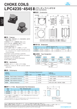
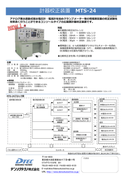
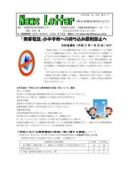
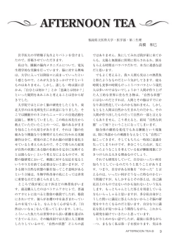
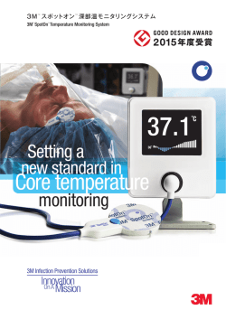
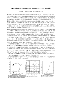
CHOKE COILS
LKS
EU
RoHS
パワーチップインダクタ 磁気シールドタイプ
Power Chip Inductors Shielded Type
■構造図及び外形寸法 Construction and Dimensions
B
E
F100
J4D
① フェライトコア
② 電極
A
インダクタ
Inductor
C
D
①
Ferite core
Electrode
②
■特長 Features
●
●
●
●
●
●
●
●
●
●
洩磁束が少ない閉磁タイプのパワーチップイン
漏
ダクタ。
小型、薄型。
直流抵抗値が小さく、定格電流が大きい。
リフローはんだ付けに対応します。
欧州RoHS対応品です。
Magnetic shielded power chip inductors with a
little leakage magnetic flux.
Small size and Low-profile.
Low DC Resistance and larger Rated Current.
Suitable for reflow soldering.
Products meet EU-RoHS requirements.
形 名
Type
LKS0745
LKS1045
LKS1260
●
種電子機器のDC-DCコンバータ
各
DC-DC converter for various electric equipments.
LKS
0745
T
TEG
100
M
品 種
Product
Code
形 状
Style
(mm)
端子表面材質
Termination
Surface Material
二次加工
Taping
公称インダクタンス
Nominal
Inductance
許容差
Tolerance
0745
1045
1260
T:Sn
TEG:Plastic
embossed
BK:Bulk
3 digits
M:±20%
N:±30%
環境負荷物質含有についてEU-RoHS以外の物質に対するご要求がある場合にはお問合せください。
テーピングの詳細については巻末のAPPENDIX Cを参照してください。
Contact us when you have control request for environmental hazardous material other than the substance specified
by EU-RoHS.
For further information on taping, please refer to APPENDIX C on the back pages.
■定格 Ratings
LKS0745 包装数/リール Q’
ty/Reel:1000pcs
形 名
Type
インダクタンス
直流抵抗
公称インダクタンス
許容差
DC
Nominal
Inductance
Resistance
Inductance(μH)
Tolerance
(Ω)Max.
E±0.2
2.0
3.0
5.0
■品名構成 Type Designation
例 Examples
■用途 Applications
●
寸 法 Dimensions (mm)
A
B
C Max.
D±0.3
7.5±0.5 7.5±0.5
4.5
1.0
10.1±0.3 10.1±0.3
4.5
2.0
12.5±0.3 12.5±0.3
6.0
1.5
LKS1045 包装数/リール Q’
ty/Reel:1000pcs
許容直流電流
Allowable
DC Current
(A)Max.※1
SRF
(MHz)
Typ.
形 名
Type
インダクタンス
直流抵抗
公称インダクタンス
許容差
DC
Nominal
Inductance
Resistance
Inductance(μH)
Tolerance
(Ω)Max.
許容直流電流
Allowable
DC Current
(A)Max.※1
SRF
(MHz)
Typ.
LKS0745 TTEG 3R3N
3.3
0.022
4.5
41
LKS1045 TTEG 3R3N
3.3
0.017
5.8
37
LKS0745 TTEG 4R7N
4.7
0.031
3.8
34
LKS1045 TTEG 4R7N
4.7
0.022
5.1
31
LKS0745 TTEG 5R6N
5.6
0.035
3.6
31
LKS1045 TTEG 5R6N
5.6
0.024
4.9
28
LKS0745 TTEG 6R8N
6.8
0.038
3.4
28
LKS1045 TTEG 6R8N
6.8
0.027
4.6
25
LKS0745 TTEG 8R2N
8.2
0.050
2.8
25
LKS1045 TTEG 8R2N
8.2
0.032
4.0
23
N:±30%
N:±30%
LKS0745 TTEG 100M
10
0.057
2.6
24
LKS1045 TTEG 100M
10
0.042
3.6
21
LKS0745 TTEG 120M
12
0.067
2.4
22
LKS1045 TTEG 120M
12
0.043
3.4
19
LKS0745 TTEG 150M
15
0.100
2.1
19
LKS1045 TTEG 150M
15
0.065
3.0
17
LKS0745 TTEG 180M
18
0.113
2.0
17
LKS1045 TTEG 180M
18
0.066
2.9
15
LKS0745 TTEG 220M
22
0.127
1.9
16
LKS1045 TTEG 220M
22
0.089
2.5
14
LKS0745 TTEG 330M
33
0.199
1.5
13
LKS1045 TTEG 330M
33
0.159
1.9
11
LKS0745 TTEG 470M
47
0.253
1.3
11
LKS1045 TTEG 470M
47
0.196
1.7
9
LKS0745 TTEG 560M
56
0.288
1.3
10
LKS1045 TTEG 560M
56
0.215
1.5
8
LKS0745 TTEG 680M
68
0.437
1.0
9
LKS1045 TTEG 680M
68
0.242
1.4
8
LKS0745 TTEG 820M
82
0.483
1.0
8
LKS1045 TTEG 820M
82
0.265
1.3
7
LKS0745 TTEG 101M
100
0.598
0.9
7
LKS1045 TTEG 101M
100
0.414
1.2
6
LKS0745 TTEG 121M
120
0.644
0.8
6
LKS1045 TTEG 121M
120
0.472
1.0
6
LKS0745 TTEG 151M
150
0.817
0.7
6
LKS1045 TTEG 151M
150
0.575
0.9
5
LKS0745 TTEG 181M
180
0.897
0.7
5
LKS1045 TTEG 181M
180
0.633
0.8
4
LKS0745 TTEG 221M
220
1.104
0.6
5
LKS1045 TTEG 221M
220
0.874
0.7
4
LKS0745 TTEG 331M
330
2.093
0.5
4
LKS1045 TTEG 331M
330
1.300
0.6
3
LKS0745 TTEG 471M
470
2.576
0.4
3
LKS1045 TTEG 471M
470
1.716
0.5
3
LKS0745 TTEG 561M
560
4.200
0.31
3
LKS0745 TTEG 681M
680
4.680
0.27
3
LKS0745 TTEG 821M
820
6.360
0.24
2
LKS0745 TTEG 102M
1000
6.600
0.23
2
M:±20%
M:±20%
本カタログに掲載の仕様は予告なく変更する場合があります。ご注文およびご使用前に納入仕様書で内容をご確認ください。
Oct. 2016
車載機器、医療機器、航空機器など人命に関わったり、あるいは甚大な損害を引き起こす可能性のある機器へのご使用を検討される場合には、必ず事前にご相談ください。
Specifications given herein may be changed at any time without prior notice. Please confirm technical specifications before you order and/or use.
Contact our sales representatives before you use our products for applications including automotives, medical equipment and aerospace equipment.
www.koaglobal.com
Malfunction or failure of the products in such applications may cause loss of human life or serious damage.
■性能 Performance
LKS1260 包装数/リール Q’
ty/Reel:700pcs
形 名
Type
TTEG
TTEG
TTEG
TTEG
TTEG
TTEG
TTEG
TTEG
TTEG
TTEG
TTEG
TTEG
TTEG
TTEG
TTEG
TTEG
TTEG
TTEG
TTEG
TTEG
TTEG
TTEG
TTEG
TTEG
TTEG
TTEG
TTEG
TTEG
TTEG
TTEG
TTEG
TTEG
3R3N
4R7N
5R6N
6R8N
8R2N
100M
120M
150M
180M
220M
330M
470M
560M
680M
820M
101M
121M
151M
181M
221M
331M
471M
561M
681M
821M
102M
152M
222M
332M
472M
682M
103M
試験項目
Test Items
試験方法
Test Methods
規格値
Limit
熱衝撃
Heat shock
−40℃(30min.)/+120℃(30min.)
100 cycles
⊿L/L:±10%
低温放置Low temperature
exposure
−40℃, 1,000h
⊿L/L:±10%
高温放置High temperature
exposure
+120℃, 1,000h
⊿L/L:±10%
耐湿性
Moisture endurance
+85℃, 85%RH, 1,000h
⊿L/L:±10%
■推奨ランド寸法 Recommended Pad Dimensions
B
D
:はんだランド Solder pad
A
:チップ部品 Chip componment
C
形名
Type
A
5.5
5.5
9.5
LKS0745
LKS1045
LKS1260
●許容直流電流:コイルの温度上昇が⊿T=35℃以内の直流電流値、
または、イン
ダクタンス変化率が⊿L/L=−30%以内の直流電流値のいずれか小さい値。
●使用温度範囲:−40℃~+120℃(※自己発熱含む)
※コイル上面部分の温度(周囲温度+自己発熱)が使用温度上限(+120℃)以下
であること。
●Allowable DC Current: DC Current value when coil temperature rise is within
⊿T=35℃ or when inductance change ratio is within ⊿L/L=−30%,
whichever is lower.
●Operating Temperature Range:−40℃~+120℃
(※Self-heating is included.)
※That the operating temperature upper limit temperature of the coil top surface
portions.
(ambient temperature+self-heating) is (+120℃) or less.
推奨ランド寸法 Pad Dimensions(mm)
B
C
D
8.7
2.3
1.6
10.7
3.6
2.6
13.9
5.3
2.2
※これらの推奨ランド寸法は標準パターンであり、特性を保証するものではありません。
事前にご確認の上御使用ください。
※These pad dimensions are only for standard pattern and the characteristics are not
guaranteed, which you are suggested to confirm before use.
■特性 Characteristics
直流重畳特性 DC Bias Characteristics
インダクタンス
インダクタンス
Inductance(μH)
Inductance(μH)
インダクタンス
インダクタンス
Inductance(μH)
Inductance(μH)
470μH
470μH
100
100
10μH
10μH
3.3μH
3.3μH
10
10
1
10.1
0.1
LKS1045
LKS1045
1000
1000
1.0
直流電流 1.0
DC Bias (A)
470μH
470μH
100
100
10μH
10μH
10
10
1
10.1
0.1
10.0
10.0
3.3μH
3.3μH
1.0
直流電流1.0
DC Bias (A)
直流電流 DC Bias (A)
LKS1260
LKS1260
1000
1000
インダクタンス
インダクタンス
Inductance(μH)
Inductance(μH)
LKS0745
LKS0745
1000
1000
470μH
470μH
100
100
10μH
10μH
3.3μH
3.3μH
10
10
1
10.1
0.1
10.0
10.0
1.0
10.0
10.0
直流電流1.0
DC Bias (A)
直流電流 DC Bias (A)
直流電流 DC Bias (A)
表面温度上昇 Surface Temperature Rise
50
50
30
30
10μH
10μH
20
20
3.3μH
3.3μH
10
10
0
0.0
0
0.0
1.0
1.0
2.0
2.0
3.0
3.0
4.0
4.0
5.0
5.0
直流電流 DC Bias (A)
直流電流 DC Bias (A)
6.0
6.0
7.0
7.0
40
40
LKS1045
LKS1045
470μH
470μH
30
30
10μH
10μH
20
20
3.3μH
3.3μH
10
10
0
00.0
0.0
1.0
1.0
2.0
2.0
3.0
3.0
4.0
4.0
LKS1260
LKS1260
50
50
温度上昇ΔT(℃)
温度上昇ΔT(℃)
Temperature
Temperature
Rise
Rise
40
40
LKS0745
LKS0745
470μH
470μH
温度上昇ΔT(℃)
温度上昇ΔT(℃)
Temperature
Temperature
Rise
Rise
温度上昇ΔT(℃)
温度上昇ΔT(℃)
Temperature
Temperature
Rise
Rise
50
50
5.0
5.0
直流電流 DC Bias (A)
直流電流 DC Bias (A)
6.0
6.0
7.0
7.0
470μH
470μH
40
40
30
30
10μH
10μH
20
20
10
10
0
00.0
0.0
3.3μH
3.3μH
1.0
1.0
2.0
2.0
3.0
3.0
4.0
4.0
5.0
5.0
直流電流 DC Bias (A)
直流電流 DC Bias (A)
6.0
6.0
7.0
7.0
■使用上の注意 Precautions for Use
●
●
●
●
●
インダクタに強い力、過度の衝撃を加えると電気、磁性特性が変化することがありますので、搭載時及び搭載後に過度の衝撃が加わらないようにしてください。
完全磁気シールド品でないため、コイル同士の間隔が狭いと磁気結合をおこす事があります。コイルの部品配置に考慮のうえ回路設計してください。
フェライトを使用した製品のため、スイッチング周波数により、発熱量が異なるので製品の温度は、使用温度範囲内で使用してください。
Avoid strong pressure or excessive shock at mounting or after mounting because electric/magnetic characteristics may change if it is applied to the inductors.
The narrow space between inductors may cause magnetic coupling because they are not magnetic shielded perfectly . Make designing of a circuit by talking into
consideration the parts layout for inductors.
●
Due to the product used the ferrite, use them within each operating temperature range, because calorific power differs from switching frequency.
本カタログに掲載の仕様は予告なく変更する場合があります。ご注文およびご使用前に納入仕様書で内容をご確認ください。
Oct. 2016
車載機器、医療機器、航空機器など人命に関わったり、あるいは甚大な損害を引き起こす可能性のある機器へのご使用を検討される場合には、必ず事前にご相談ください。
Specifications given herein may be changed at any time without prior notice. Please confirm technical specifications before you order and/or use.
Contact our sales representatives before you use our products for applications including automotives, medical equipment and aerospace equipment.
www.koaglobal.com
Malfunction or failure of the products in such applications may cause loss of human life or serious damage.
インダクタ
Inductor
LKS1260
LKS1260
LKS1260
LKS1260
LKS1260
LKS1260
LKS1260
LKS1260
LKS1260
LKS1260
LKS1260
LKS1260
LKS1260
LKS1260
LKS1260
LKS1260
LKS1260
LKS1260
LKS1260
LKS1260
LKS1260
LKS1260
LKS1260
LKS1260
LKS1260
LKS1260
LKS1260
LKS1260
LKS1260
LKS1260
LKS1260
LKS1260
インダクタンス 直流抵抗 許容直流電流
公称インダクタンス
SRF
許容差
DC
Allowable
Nominal
(MHz)
Inductance Resistance DC Current
Inductance(μH)
Typ.
Tolerance (Ω)Max. (A)Max.※1
3.3
0.011
6.6
34
4.7
0.012
6.3
28
N:±30%
5.6
0.014
5.8
25
6.8
0.015
5.6
23
8.2
0.019
5.0
21
10
0.021
4.8
19
12
0.023
4.6
18
15
0.026
4.3
16
18
0.034
3.8
14
22
0.040
3.5
13
33
0.058
2.9
10
47
0.083
2.4
8
56
0.093
2.3
8
68
0.127
1.9
7
82
0.140
1.8
6
100
0.157
1.7
6
120
0.181
1.5
5
150
0.247
1.2
5
180
0.301
1.1
4
M:±20%
220
0.355
1.0
4
330
0.566
0.8
3
470
0.853
0.7
2
560
1.210
0.68
1.9
680
1.370
0.66
1.8
820
1.810
0.57
1.7
1000
1.950
0.55
1.5
1500
2.950
0.45
1.2
2200
4.270
0.37
0.9
3300
5.900
0.31
0.8
4700
9.560
0.25
0.6
6800
16.400
0.19
0.5
10000
26.000
0.15
0.4
© Copyright 2026 Paperzz