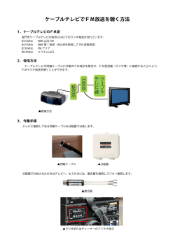
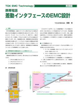
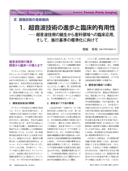
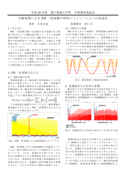
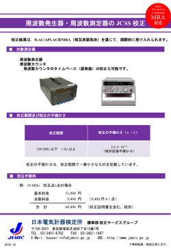
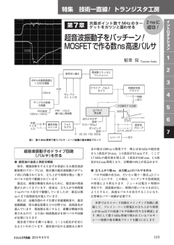
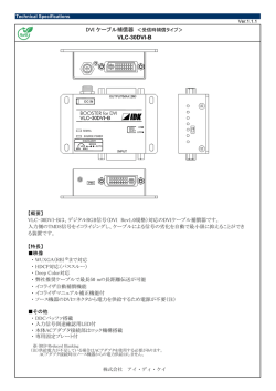
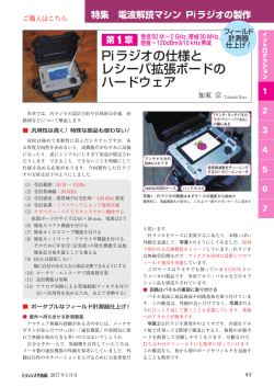
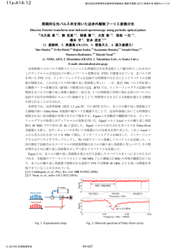
NCS2553 フィルタき3チャ ネル・ビデオ・アンプ NCS2553は、6バターワース フィルタき3 チャネルビデオ・アンプです。 3チャネルすべてが、コンポーネント・ビデオおよび RGBビデオ、またはコンポジットおよびSビデオ のいずれかに !できます。チャネルがDCまたはAC"# を$け%れることができます。AC"#の&#、'(クラン プが*+されます。,-は、ACおよびDC"#150 W./をド ライブできます。 ほとんどのビデオ・プロセッサに4み5まれている、6( 7のデジタル−アナログ・コンバータ(DAC)と9:;があるよ うに<=されています。 3>の6 8MHzフィルタ '(?@ゲイン = 6dB ACまたはDC"#%ACまたはDC"#,ABCレベル・シフタ FGHI +5V SOIC−8パッケージでKL Mフリー・デバイス 8 1 SOIC−8 NB D SUFFIX CASE 751 N2553 ALYW G 1 = Assembly Location = Wafer Lot = Year = Work Week = Pb−Free Package PINOUT 8 SD OUT1 SD IN1 1 SD IN2 2 アプリケーション • • • • • MARKING DIAGRAM 8 A L Y W G • • • • • • • • http://onsemi.com デジタル・セットトップ・ボックス DVD/ビデオ・プレーヤおよびQRST SD−TV ビデオ・オン・デマンド(VOD) ビデオ・レコーダ NCS2553 SOIC−8 SD IN3 3 7 SD OUT2 6 SD OUT3 VCC 4 5 GND ORDERING INFORMATION Package Shipping† NCS2553DG SOIC−8 (Pb−Free) 98 Units / Rail NCS2553DR2G SOIC−8 (Pb−Free) 2500 / Tape & Reel Device †For information on tape and reel specifications, including part orientation and tape sizes, please refer to our Tape and Reel Packaging Specifications Brochure, BRD8011/D. © Semiconductor Components Industries, LLC, 2008 December, 2008 − Rev. 4 1 Publication Order Number: NCS2553JP/D NCS2553 SD IN1 Transparent Clamp 6dB SD OUT1 6dB SD OUT2 6dB SD OUT3 8 MHz, 6th Order Transparent Clamp SD IN2 8 MHz, 6th Order Transparent Clamp SD IN3 8 MHz, 6th Order Figure 1. Block Diagram PIN FUNCTION AND DESCRIPTION Pin Name Type Description 1 IN1 Input Video Input 1 for Video Signal featuring a frequency bandwidth compatible with Standard Definition Video (8 MHz) − Channel 1 2 IN2 Input Video Input 2 for Video Signal featuring a frequency bandwidth compatible with Standard Definition Video (8 MHz) − Channel 2 3 IN3 Input Video Input 3 for Video Signal featuring a frequency bandwidth compatible with Standard Definition Video (8 MHz) − Channel 3 4 VCC Power Device Power Supply Voltage: +5 V 5 GND GND Connected to Ground 6 OUT3 Output SD Video Output 3 − Channel 3 7 OUT2 Output SD Video Output 2 − Channel 2 8 OUT1 Output SD Video Output 1 − Channel 1 ATTRIBUTES Characteristics ESD Human Body Model Machine Model Value All Pins (Note 1) Pins 1 to 5 (Note 2) All Output Pins (Note 2) 8 kV 400 V 800 V Moisture Sensitivity (Note 3) Level 1 Flammability Rating − Oxygen Index: 28 to 34 UL 94 V−0 @ 0.125 in 1. Human Body Model (HBM): R = 1500 W, C = 100 pF 2. Machine Model (MM) 3. For additional information, see Application Note AND8003/D. http://onsemi.com 2 NCS2553 MAXIMUM RATINGS Parameter Symbol Rating Unit VCC −0.35 v VCC v 5.5 Vdc Input Voltage Range VI −0.3 v VI v VCC Vdc Input Differential Voltage Range VID VI v VCC Vdc Output Current IO 50 mA Maximum Junction Temperature (Note 4) TJ 150 °C Operating Ambient Temperature TA −40 to +85 °C Storage Temperature Range Tstg −60 to +150 °C Power Dissipation PD (See Graph) mW RqJA 112.7 °C/W Power Supply Voltages Thermal Resistance, Junction−to−Air Stresses exceeding Maximum Ratings may damage the device. Maximum Ratings are stress ratings only. Functional operation above the Recommended Operating Conditions is not implied. Extended exposure to stresses above the Recommended Operating Conditions may affect device reliability. 4. Power dissipation must be considered to ensure maximum junction temperature (TJ) is not exceeded. 1800 !"#$%& WにXYZ[な\6H-は、QRする]#(^ _の`aによってbcされます。 プラスチック・パッケージの&#、\6W]# (^_は150°Cです。defに\6gをhえた&#、 ダイ^_がijするとすぐにklなmnFGがmo します。デバイスをpqr「st」uvにwくと、 デバイス・バーンアウトがxするZ[;がありま す。klなFGをyzするには、ディレーティング |}を~することが6lです。 POWER DISSIPATION (mW) 1600 1400 1200 1000 800 600 400 200 0 −40 −30−20−10 0 10 20 30 40 50 60 70 80 90100 TEMPERATURE (°C) Figure 2. Power Dissipation vs Temperature http://onsemi.com 3 NCS2553 DC ELECTRICAL CHARACTERISTICS (VCC = +5.0 V, TA = 25°C, 0.1 mF AC coupled inputs, Rsource = 37.5 W, 220 mF AC coupled outputs into 150 W load, referenced to 400 kHz, unless otherwise specified) Symbol Characteristics VCC Supply Voltage Range ICC Power Supply Current VIN Input Common Mode Voltage Range PSRR Power Supply Rejection Conditions Min Typ Max Unit 4.75 5.0 5.25 V 23 30 mA No Load Referenced to GND if DC−Coupled GND DC (All Channels) 1.4 −50 dB NOTE: Device will meet the specifications after thermal equilibrium has been established when mounted in a test socket or printed circuit board with maintained transverse airflow greater than 500 lfpm. Electrical parameters are guaranteed only over the declared operating temperature range. Functional operation of the device exceeding these conditions is not implied. Device specification limit values are applied individually under normal operating conditions and not valid simultaneously. AC ELECTRICAL CHARACTERISTICS (VCC = +5.0 V, TA = 25°C, 0.1 mF AC coupled inputs, Rsource = 37.5 W,220 mF AC coupled outputs into 150 W load, referenced to 400 kHz, unless otherwise specified) Symbol Characteristics AVOL Voltage Gain (Note 5) BW Low Pass Filter Bandwidth Conditions Min Typ Max Unit VIN = 1 V (All Channels) 5.8 6.0 6.2 dB −1 dB (Note 6) 5.5 7.2 MHz −3 dB 9.0 MHz at 27 MHz 45 dB 0.3 % AR Stop−Band Attenuation (Rejection) dG Differential Gain dq Differential Phase 0.6 _ THD Total Harmonic Distortion VOUT = 1.8 VPP @ 1 MHz 0.4 % Xtalk Channel−to−Channel Crosstalk VOUT = 1.8 VPP @ 1 MHz −60 dB SNR Signal−to−Noise Ratio NTSC−7, 100 kHz to 4.2 MHz (Note 7) 75 dB Tpd Propagation Delay Input−to−Output, 4.5 MHz 60 nsec DGD Group Delay Variation from 100 kHz to 8 MHz 27 ns NOTE: Device will meet the specifications after thermal equilibrium has been established when mounted in a test socket or printed circuit board with maintained transverse airflow greater than 500 lfpm. Electrical parameters are guaranteed only over the declared operating temperature range. Functional operation of the device exceeding these conditions is not implied. Device specification limit values are applied individually under normal operating conditions and not valid simultaneously. 5. 100% of tested IC fit to the bandwidth tolerance. 6. Guaranteed by design and characterization. 7. SNR = 20 x log (714 mV/RMS Noise) http://onsemi.com 4 NCS2553 TYPICAL CHARACTERISTICS VCC = +5.0 V, Rsource = 37.5 W, TA = 25°C, 0.1 mF AC−coupled inputs, 220 mF AC−coupled outputs into 150 W referenced to 400 kHz, all channels, unless otherwise specified −35 6.7 MHz, −0.5 dB 6 dB 9.0 MHz, −3 dB 0 GAIN (dB) −10 −45 7.2 MHz, −1 dB −20 −30 −40 −50 27 MHz Stop−band Rejection = 46 dB (6 dB − (−40 dB)) −60 −70 Vin = 4 dBm Zout = 150 W −80 0.01 0.1 1 10 6.7 MHz, −43 dB −40 −50 CROSSTALK (dB) 20 10 −55 −60 1 MHz, −60 dB −65 −70 −75 −80 −85 100k 100 Vin = 4 dBm Zout = 150 W 8M 1M FREQUENCY (MHz) FREQUENCY (Hz) Figure 3. Frequency Response Figure 4. Channel−to−Channel Crosstalk 110 70 60 50 40 20 10 100k 3.0 1.5 2.6 1.25 0.75 1.2 79 ns 0.5 0.8 Output 0.25 0.4 0 −0.75 1M 10M 30M 0 −0.4 50 100 150 200 250 300 350 400 450 500 FREQUENCY (Hz) TIME (ns) Figure 5. Group Delay Figure 6. Propagation Delay −45 −45 −50 −50 −55 −55 −60 −60 −65 −65 −70 −75 −80 −70 −75 −80 −85 −95 100k 1.6 0 Vin = 4 dBm Zout = 150 W −90 2.0 Input 1.0 OUTPUT VOLTAGE (V) 80 30 PSRR (dB) INPUT VOLTAGE (V) 90 1.75 PSRR (dB) GROUP DELAY (ns) 100 −85 Vin = −22 dBm Zout = 150 W −90 1M 10M −95 100k 50M FREQUENCY (Hz) Vin = −22 dBm Zout = 150 W 1M FREQUENCY (Hz) 10M Figure 8. PSRR vs. Frequency (Bypass Capacitor) Figure 7. PSRR vs Frequency (No Bypass Capacitor) http://onsemi.com 5 50M NCS2553 TYPICAL CHARACTERISTICS VCC = +5.0 V, Rsource = 37.5 W, TA = 25°C, 0.1 mF AC−coupled inputs, 220 mF AC−coupled outputs into 150 W referenced to 400 kHz, all channels, unless otherwise specified 6.4 6.2 GAIN (dB) 3.8 MHz, 6.19 dB 400 kHz, 6.04 dB 6 5.5 MHz, 6.00 dB 5.8 5.6 5.4 0.01 6.7 MHz, 5.5 dB Vin = 4 dBm Zout = 150 W 0.1 1 FREQUENCY (Hz) 10 Figure 9. Gain Flatness 0.5 1.2 0.46 0.35 0.35 0.3 0.3 0.25 0.18 0.2 0.15 0.1 0.04 0.05 0.81 0.8 0.61 0.6 0.6 0.44 0.4 0.2 0 0 1 0.96 1 2 3 4 5 0 6 1 2 3 4 5 6 HARMONIC NUMBERS HARMONIC NUMBERS Figure 10. Differential Gain (NTSC 5 Steps Input Signal) Figure 11. Differential Phase (NTSC 5 Steps Input Signal 120 20 Gain 105 10 90 0 75 −10 60 −20 45 −30 Group Delay 30 −40 15 −50 0 −60 −15 −70 −30 20k 100k 1M FREQUENCY (Hz) 10M GAIN (dB) 0 DIFFERENTIAL PHASE (°) 0.4 GROUP DELAY (ns) DIFFERENTIAL GAIN (%) 0.45 −80 40M Figure 12. Normalized Frequency Response and Group Delay vs. Frequency http://onsemi.com 6 NCS2553 アプリケーション'( NCS2553トリプル・ビデオ・ドライバは、CVBS、 Sビデオ、480i/525i & 576i/625iのに !するビデオ・ア プリケーションけに\kCされています。いチ ャネルrクロストークのによって、3チャネル すべてがで、なFGをすることがyz されます。チャネルは%-から,-に'(HI− HIゲイン2をKし、ディスクリート・アプロー チ(したオペアンプを+)の&#に なけ(をします。'(レベル・シフ タを*+し、280mVのオフセットを して、, -HIをくしています。これによって、qパル スのクリップを¡¢し、150Wのビデオ./に する DC"#,-をZ[にします。また、NCS2553は、チ ャネルごとに8MHzの3dB£¤¥¦§を¨つ6バ ターワース・フィルタを'©しています。これによ って、ビデオDACによりxするエイリアスやªま しくないオーバサンプリングの«¬をり®くこと ができます。に、ADCを+したDVDレコーダ のケースでは、このアンチエリアシング・フィルタ (フィルタ)は の¯°をm±し、EMI²³ に´µする¶を®·するのに¸ちます。 チップ'でチャネルに して'©ダイオードの ようなクランプが+され、AC"#FGモードをサ ポートします。%-が0Vºjになると、クラン プが»¼になります。 2.28V 1V Y, R’, G’, B’ 1VPP 0V 0.1mF IN1 Clamp 0.28V 220mF LS 8MHz 75W OUT1 0.1mF IN2 DAC Clamp 800k RS 0.1mF IN3 Clamp 800k RS 6db 220mF LS 8MHz 6db 280mV LS 8MHz 220mF 280mV 6db ZO = 75W 75W ZO = 75W 75W ZO = 75W 75W 75W OUT2 OUT3 800k RS 280mV 75W 1.68V 0.7V Pb, Pr 0V 0.28V 0.7VPP Figure 13. AC−Coupled Inputs and Outputs ¿えば、%-̧が0〜1.4VのÍÎをhえた り、ビデオ・ソースでになる&#、%-はAC "#されます。uÏによっては、プルアップÐÑと プルダウンÐÑまたはプルアップÐÑのみ( 7.5MWと'(800kWプルダウン)を して、クラ ンプをÇアクティブすることによって、をÒF バイアスしなければならない&#があります。 ,-のAC"#ÅÆには、,-カップリング・コン デンサのÓÔがiすぎる&#に、デバイスがビデオ ・ラインやフィールドÕき¯°に してよりÖ×に なるというØはありますが、DCグランド・ループ をなくすËがあります。&#によっては、ÙÚ 220 mFのコンデンサgをÛやすがあります。 Figure 13に、DACから½る(ビデオ・ソースが %-および,-でAC"#される¿をÀします。しか し、'©トランスペアレント・クランプおよびレベ ル・シフタのために、デバイスはÁÂfにDAC,レベルのハイおよびローに!じて、またビデオ ・ドライバの%-コモン・モードHIにどのように k#するかに!じて、ÄなるÅÆモードでFGする ことができます。ÅÆが%-および,-でのDC"# の&#、0.1mFおよび220 mFのカップリング・コンデ ンサは+されず、クランプはÇアクティブになり ます。このÅÆにはけ(がÈなく、ÉÊ fiコストであるという6きなËがあります。 http://onsemi.com 7 NCS2553 DVD Player or STB +5 V 0.1 mF 1 R/Pr 10 mF IN1 OUT1 8 Video SOC 2 IN2 OUT2 NCS2553 RS 3 B/Pd RS R/Pr 75 W RS G/Y 75 W 220 mF 75 W Video Cables IN3 OUT3 7 75 W 220 mF 75 W Video Cables G/Y 75 W 6 75 W 220 mF 75 W Video Cables B/Pd 75 W 4 VCC GND 5 DAC Load Resistors AC−Coupling Caps are Optional Figure 14. Typical Application Circuit http://onsemi.com 8 NCS2553 PACKAGE DIMENSIONS SOIC−8 NB CASE 751−07 ISSUE AJ NOTES: 1. DIMENSIONING AND TOLERANCING PER ANSI Y14.5M, 1982. 2. CONTROLLING DIMENSION: MILLIMETER. 3. DIMENSION A AND B DO NOT INCLUDE MOLD PROTRUSION. 4. MAXIMUM MOLD PROTRUSION 0.15 (0.006) PER SIDE. 5. DIMENSION D DOES NOT INCLUDE DAMBAR PROTRUSION. ALLOWABLE DAMBAR PROTRUSION SHALL BE 0.127 (0.005) TOTAL IN EXCESS OF THE D DIMENSION AT MAXIMUM MATERIAL CONDITION. 6. 751−01 THRU 751−06 ARE OBSOLETE. NEW STANDARD IS 751−07. −X− A 8 5 S B 0.25 (0.010) M Y M 1 4 −Y− K G C N DIM A B C D G H J K M N S X 45 _ SEATING PLANE −Z− 0.10 (0.004) H D 0.25 (0.010) M Z Y S X M J S MILLIMETERS MIN MAX 4.80 5.00 3.80 4.00 1.35 1.75 0.33 0.51 1.27 BSC 0.10 0.25 0.19 0.25 0.40 1.27 0_ 8_ 0.25 0.50 5.80 6.20 INCHES MIN MAX 0.189 0.197 0.150 0.157 0.053 0.069 0.013 0.020 0.050 BSC 0.004 0.010 0.007 0.010 0.016 0.050 0 _ 8 _ 0.010 0.020 0.228 0.244 SOLDERING FOOTPRINT* 1.52 0.060 7.0 0.275 4.0 0.155 0.6 0.024 1.270 0.050 SCALE 6:1 mm Ǔ ǒinches *For additional information on our Pb−Free strategy and soldering details, please download the ON Semiconductor Soldering and Mounting Techniques Reference Manual, SOLDERRM/D. ON Semiconductor and are registered trademarks of Semiconductor Components Industries, LLC (SCILLC). SCILLC reserves the right to make changes without further notice to any products herein. SCILLC makes no warranty, representation or guarantee regarding the suitability of its products for any particular purpose, nor does SCILLC assume any liability arising out of the application or use of any product or circuit, and specifically disclaims any and all liability, including without limitation special, consequential or incidental damages. ”Typical” parameters which may be provided in SCILLC data sheets and/or specifications can and do vary in different applications and actual performance may vary over time. All operating parameters, including ”Typicals” must be validated for each customer application by customer’s technical experts. SCILLC does not convey any license under its patent rights nor the rights of others. SCILLC products are not designed, intended, or authorized for use as components in systems intended for surgical implant into the body, or other applications intended to support or sustain life, or for any other application in which the failure of the SCILLC product could create a situation where personal injury or death may occur. Should Buyer purchase or use SCILLC products for any such unintended or unauthorized application, Buyer shall indemnify and hold SCILLC and its officers, employees, subsidiaries, affiliates, and distributors harmless against all claims, costs, damages, and expenses, and reasonable attorney fees arising out of, directly or indirectly, any claim of personal injury or death associated with such unintended or unauthorized use, even if such claim alleges that SCILLC was negligent regarding the design or manufacture of the part. SCILLC is an Equal Opportunity/Affirmative Action Employer. This literature is subject to all applicable copyright laws and is not for resale in any manner. PUBLICATION ORDERING INFORMATION LITERATURE FULFILLMENT: Literature Distribution Center for ON Semiconductor P.O. Box 5163, Denver, Colorado 80217 USA Phone: 303−675−2175 or 800−344−3860 Toll Free USA/Canada Fax: 303−675−2176 or 800−344−3867 Toll Free USA/Canada Email: [email protected] N. American Technical Support: 800−282−9855 Toll Free USA/Canada Europe, Middle East and Africa Technical Support: Phone: 421 33 790 2910 Japan Customer Focus Center Phone: 81−3−5773−3850 http://onsemi.com 9 ON Semiconductor Website: www.onsemi.com Order Literature: http://www.onsemi.com/orderlit For additional information, please contact your local Sales Representative NCS2553JP/D
© Copyright 2026 Paperzz