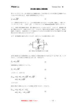
AC SERVO SYSTEMS
R
R AMPLIFIERS / Q MOTORS
400V AC 0.5kW to 20kW
3
Ver.
サーボシステム サンモーションR
Input voltage 電源電圧
Servo amplifier
Amp. capacity
アンプ容量
フランジサイズ
Rated output
定格出力
サーボアンプ
25A・50A・100A・150A・300A
Servo motor
Flange size
AC400V
サーボモータ
86mm・100mm・130mm・180mm・220mm
0.5kW・1.0kW・1.5kW・2.0kW・3.5kW・4.5kW・5.5kW
7.0kW・7.5kW・11kW・15kW・20kW
Index 目次
Features and Functions ・・・・・・・・・・・・ P. 3
特長
Standard Model Number List ・・・・・ P. 7
標準型番リスト
Model Number Nomenclature ・・・・・・ P. 9
型番の見方
System Configuration ・・・・・・・・・・・・・ P. 11
システム構成図
Standard Specifications ・・・・・・・・・・ P. 13
一般仕様
External Wiring Diagram ・・・・・・・・・・ P. 19
外部接続図
Encoder Wiring Diagram ・・・・・・・・・ P. 23
エンコーダ接続図
Dimensions ・・・・・・・・・・・・・・・・・・・・・・ P. 25
外形図
Setup Software ・・・・・・・・・・・・・・・・・・ P. 28
セットアップソフトウェア
Optional Equipment・・・・・・・・・・・・・・ P. 30
オプション
Easy Set-up for Optimal Operation
最適運転のセットアップが簡単にできます。
Auto-Tuning
Protection code IP67
オートチューニング
保護等級 IP67
A new auto-tuning algorithm improves
system response by providing functions
such as inertia identification, 5 autotuning modes, 30 levels of response, and
parameter setting auto-save.
Protection code is IP67 for all models.
全機種,保護等級はIP67です。
IP67
新アルゴリズムを用いたイナーシャ同定機能と 5 種類のオート
チューニング特性の選択,30 段階の応答性の設定やパラメータ
の自動保存機能により,応答性を高めたオートチューニングが実
現できます。
water
水
dust
ほこり
Velocity command value
速度指令値
Tuning start
Detected velocity value
チューニング開始
速度検出値
*Shaft feedthrough and cable end are excluded.
※軸貫通部,ケーブル端を除きます。
All-in-One Control
Setup Software
オールインワン制御
セットアップソフトウェア
Configurable parameters allow you
to switch between control modes for
torque, position or velocity.
The setup software allows you to set
parameters, view graphical displays
of monitored position, velocity or
torque waveforms, and perform system
analysis.
トルク・位置・速度制御を,パラメータを切り換えることにより
使い分けることができます。
セットアップソフトウェアにより,パラメータの設定や位置,
速度,トルクなどのモニタ波形のグラフィック表示,さらに
システムアナリシスなどがおこなえます。
Position
位置
or
Torque
control
Velocity
トルク制御
ng
上 en
り d
坂 i
sc
3
A
RT
Flat
平坦路
AL
Parameters setting
Monitoring waveforms
of position, speed, and torque
パラメータの設定
速度
STA
GO
位置,速度,トルクモニタ波形
Features and
Functions
ダイナミックブレーキ内蔵
On-board JOG operation function is
available for testing servo motor and
servo amplifier connection without the
need to connect to host device.
A built-in dynamic brake provides
emergency stop capability. The six kinds
of motion sequences for the dynamic
brake can be selected by parameter setting.
サーボモータ・サーボアンプ間の接続を確認できるジョグ機能を
搭載しており,上位コントローラと接続することなく試運転がで
きます。
Capable of JOG operation without
非常停止用にダイナミックブレーキを内蔵しています。
パラメータにより6種類のダイナミックブレーキの動作から選択
できます。
connecting to host device
上位コントローラと接続せずに試運転ができます。
回転速度
Rotation speed
Controlled state
制御状態
Dynamic-braking state
ダイナミックブレーキ状態
Time 時間 (s)
External Wiring
Diagram
Standard
Specifications
(min−1)
Model Number
Nomencalture
Built-in Dynamic Brake
試運転機能(ジョグ機能)
System
Configuration
Test Function (JOG)
* Without dynamic brake circuit for model no. RS1DA30A*.
Please prepare in a user.
※ 型番:RS1D30A* のサーボアンプはダイナミックブレーキ回路は内蔵していません。
お客様にて準備をお願いします。
Multiaxial Monitor Function
Dimensions
複数軸モニタ機能
The setup software allows up to 15
amplifiers to be monitored.
Setup Software
セットアップソフトウェアは,サーボアンプを最大 15 軸までモ
ニタリングできます。
Daisy chain up to 15 units
RS232C
Optional
Equipment
最大15軸までをデイジーチェーンで
接続できます。
Maximum
15 units
最大15台
*PC connection cable is optional
※オプション
パソコン接続ケーブル
4
Improved Precision and Reduced Cycle Time
システムの精度が向上し,サイクルタイムを短縮できます。
High Response
Shorter Position Settling Time
高応答
位置決め整定時間の短縮
A 4th-order notch filter reduces phase delay
to suppress mechanical resonance and
improve velocity response of equipment.
A new algorithm drastically shortens
positioning settling time for equipment.
位相遅れを低減させる4段ノッチフィルタにより,機械系の共振
を抑制し,装置の速度応答性を向上させることができます。
新アルゴリズムの採用により,装置の位置決め整定時間を大幅に
短縮できます。
Gain (dB) ゲイン(dB)
10
0
Position deviation
-10
位置偏差
-20
-30
-40
1
5
10
50
100
Position complete signal
Settling time (0ms)
位置決め完了信号
整定時間
(0ms)
500 1000 1800
Frequency (Hz)
周波数 (Hz)
Example of positioning settling time
in highly rigid machinery
5ms/div
高剛性機械における位置決め整定例
Vibration Suppression Control
Disturbance Suppression
制振制御
外乱抑制
With feed-forward vibration suppression
control, vibrations at the processing
point and base of a machine can be
suppressed through simple tuning
procedures. Up to 4 types of vibration
control frequencies can be selected.
A new disturbance observer with
expanded applicable frequencies
suppresses disturbance from other axes
in a multi-axis configuration.
フィードフォワード制振制御により,簡単な調整で機械先端の
振動や機台振動を抑制できます。また,振動を抑制する周波数を
4種類設定し,選択して使用することができます。
適用周波数を広げた新外乱オブザーバにより,多軸構成での他の
軸の影響を抑制することができます。
Disturbance observer function ON
Oscillation waveform
of direct drive section
Disturbance
Position deviation during stop
停止時
位置偏差
With vibration suppression control
振動抑制制御あり
Without vibration suppression control
振動抑制制御なし
Disturbance observer function OFF
100ms/div
With vibration
suppression control
制振制御 あり
Without vibration
suppression control
Oscillation waveform
of direct drive section
制振制御 なし
Disturbance
5
Features and
Functions
Full Closed-Loop Control
指令追従制御
フルクローズド制御
Performance of the positioning doubled
in comparison with current models by
adoption of new positioning control
algorithm and new speed control algorithm.
And position deviation ≒ 0 is achieved.
Optional support for full closed-loop control
using linear scale and other high resolution
encoders mounted on device side.
装置側に取り付けたリニアスケールや,高分解能エンコーダの
情報を用いたフルクローズド制御ができます。
System
Configuration
新位置制御・速度制御アルゴリズムの採用により,位置制御の
追従性を当社従来比2倍向上させました。また位置偏差≒0を
実現しました。
Position command
位置指令
Standard
Specifications
Highly accurate
positioning is possible
高精度位置決めを実現できます。
Loa
d
負荷
Position deviation
External Wiring
Diagram
位置偏差
20ms/div
High Resolution
Dimensions
高分解能
Support for encoders up to 17 bit
(131,072 divisions) is available for high
resolution control.
Setup Software
17 bit (131,072 分割)のエンコーダを搭載しています。
分
17
解
ブソ
ア
能
Optional
Equipment
高
n
d i v i s io n s) A bs o l ut e
E nc
,072 7bi(
31,072分割
1
3
od
)
1 t 1
(1
ート
er
t
i
ュ
b
リ
Hi g
hR
es
ol
u
高分解能エンコーダに適した制御ができます。
ti o
Model Number
Nomencalture
Command Follow-up Control
6
Servo Motor Standard Model Number List サーボモータ 標準型番リスト
400V System 400V系
Power Voltage
電源電圧
Encoder models
エンコーダの種類
Rated Output
定格出力
0.5kW
1kW
1.5kW
2kW
Wire-saving
incremental encoder
(PP062)
省配線インクリメンタル
エンコーダ
(PP062)
Motor Flange Size
モータフランジサイズ
3.39 inch
□ 86mm
3.94 inch
□ 100mm
5.12 inch
□ 130mm
3.5kW
4.5kW
7.09 inch
□ 180mm
7.5kW
5.5kW
7kW
11kW
8.66 inch
□ 220mm
15kW
20kW
400V
0.5kW
1kW
1.5kW
2kW
Battery backup method
absolute encoder
(PA035C)
バッテリバックアップ方式
アブソリュートエンコーダ
(PA035C)
3.39 inch
□ 86mm
3.94 inch
□ 100mm
5.12 inch
□ 130mm
3.5kW
4.5kW
7.09 inch
□ 180mm
7.5kW
5.5kW
7kW
11kW
15kW
20kW
8.66 inch
□ 220mm
Holding Brake
保持ブレーキ
−
yes あり(24V)
−
yes あり(24V)
−
yes あり(24V)
−
yes あり(24V)
−
yes あり(24V)
−
yes あり(24V)
−
yes あり(24V)
−
yes あり(24V)
−
yes あり(24V)
−
yes あり(24V)
−
yes あり(24V)
−
yes あり(24V)
−
yes あり(24V)
−
yes あり(24V)
−
yes あり(24V)
−
yes あり(24V)
−
yes あり(24V)
−
yes あり(24V)
−
yes あり(24V)
−
yes あり(24V)
−
yes あり(24V)
−
yes あり(24V)
−
yes あり(24V)
−
yes あり(24V)
Model No.
型番
Q2CA08050HXS00
Q2CA08050HCS00
Q2CA10100HXS00
Q2CA10100HCS00
Q2CA13150HXS00
Q2CA13150HCS00
Q2CA13200HXS00
Q2CA13200HCS00
Q2CA18350HXS00
Q2CA18350HCS00
Q2CA18450HXS00
Q2CA18450HCS00
Q2CA18750LXS00
Q2CA18750LCS00
Q2CA22550HXS00
Q2CA22550HCS00
Q2CA22700HXS00
Q2CA22700HCS00
Q2CA2211KVXS00
Q2CA2211KVCS00
Q2CA2215KVXS00
Q2CA2215KVCS00
Q2CA2220KRXS00
Q2CA2220KRCS00
Q2CA08050HXP00
Q2CA08050HCP00
Q2CA10100HXP00
Q2CA10100HCP00
Q2CA13150HXP00
Q2CA13150HCP00
Q2CA13200HXP00
Q2CA13200HCP00
Q2CA18350HXP00
Q2CA18350HCP00
Q2CA18450HXP00
Q2CA18450HCP00
Q2CA18750LXP00
Q2CA18750LCP00
Q2CA22550HXP00
Q2CA22550HCP00
Q2CA22700HXP00
Q2CA22700HCP00
Q2CA2211KVXP00
Q2CA2211KVCP00
Q2CA2215KVXP00
Q2CA2215KVCP00
Q2CA2220KRXP00
Q2CA2220KRCP00
For specifications on other model, please contact us.
掲載型番以外の仕様についてはお問い合わせください。
7
Servo Amplifier Standard Model Number List サーボアンプ 標準型番リスト
25A
50A
100A
150A
300A
25A
50A
100A
150A
300A
RS1C02AL
RS1C05AL
RS1C10AL
RS1C15AL
RS1D30AL
RS1C02AU
RS1C05AU
RS1C10AU
RS1C15AU
RS1D30AU
For specifications on other model, please contact us.
掲載型番以外の仕様についてはお問い合わせください。
Model Number
Nomencalture
PNP
Model No.
型番
System
Configuration
NPN
Amplifi er Capacity
アンプ容量
Standard
Specifications
※回生抵抗器は外付けとなります。
Wire-saving incremental encoder,
Battery backup method absolute
encoder
省配線インクリメンタルエンコーダ,
バッテリバックアップ方式アブソリュート
エンコーダ
Selectable Output
汎用出力
External Wiring
Diagram
* The regenerative resistor is external.
DC24V
Encoder Type
エンコーダ種別
Dimensions
AC400V System
AC400V 系
Control Power
制御電源
Setup Software
CANopen
Interface
specifications
CANopen
インタフェース
仕様
Main Power
主回路電源
Optional
Equipment
Type
タイプ
Features and
Functions
400V System 400V系
8
Servo Motor Model Number Nomenclature サーボモータ型番の見方
Servo Motor
サーボモータ
Example: The following model number defines a "Q2" servomotor with 86mm flange size, 0.5kW
rated output, 3000min -1 maximum rotation speed, 24V brake, and an absolute encoder
(131,072 divisions/rotation),CE approval.
例)
「Q2 」
(中慣性)のサーボモータで,フランジ角 86mm,定格出力 0.5kW,最高回転速度 3000min-1,ブレーキ(24V),
アブソリュートエンコーダ(131072 分割/回転)
,CE マーク準拠を選定される場合の型番です。
2
Q
CA
08
050
H
C
P
00
E
Specification
仕様識別
‥‥Standard
Q series
標準
Motor Type
モータ種別
‥‥Middle inertia
Holding Brake
保持ブレーキの有無
Standard
Identification
中慣性
X‥‥Without brake
付加仕様識別
ブレーキなし
B‥‥With brake (90V)
E ‥CE Marking
C‥‥With brake (24V)
U ‥ UL
CEマーク準拠
ブレーキ付き
Supply Voltage
UL準拠
ブレーキ付き
M‥CE and UL
電源電圧
‥‥400V Motor
400V モータ
CEマーク+UL準拠
Maximum Rotation
Speed
最高回転速度
H・L‥‥ 3000min-1
V‥‥‥ 2500・2000min-1
R‥‥‥ 2000min-1
Flange Size
Rated Output
Encoder Type
フランジサイズ
定格出力
エンコーダの種類
08 ‥
10 ‥
13 ‥
18 ‥
22 ‥
050 ‥‥‥
100 ‥‥‥
150 ‥‥‥
200 ‥‥‥
350 ‥‥‥
450 ‥‥‥
86mm (3.39 inch)
100mm (3.94 inch)
130mm (5.12 inch)
180mm (7.09 inch)
220mm (8.66 inch)
0.5kW
1.0kW
1.5kW
2.0kW
3.5kW
4.5kW
550 ‥‥‥
700 ‥‥‥
750 ‥‥‥
11K ‥‥‥
15K ‥‥‥
20K ‥‥‥
S‥Wire-saving incremental encoder [PP062]
5.5kW
7.0kW
7.5kW
11kW
15kW
20kW
省配線インクリメンタルエンコーダ
[PP062]
P‥Battery backup method absolute encoder [PA035C]
バッテリバックアップ方式アブソリュートエンコーダ
[PA035C]
W‥Absolute encoder without battery [RA035C]
バッテリレスアブソリュートエンコーダ
[RA035C]
Combined Motor/Encoder Specification モータ・エンコーダの組合せ仕様
・Wire-saving Incremental Encoder
省配線インクリメンタルエンコーダ
・Absolute Encoder
アブソリュートエンコーダ
Standard
Encoder Pulse Count
機 種
RA035C
Resolver Optical Detection
System
System
2000P/R
アブソリュート型
PA035C
光学検出方式 レゾルバ方式
インクリメンタル型
エンコーダ−パルス数
分解能
Absolute Type
機 種
Incremental Type
Model
Optical Detection
System
標 準
光学検出方式
PP062
Resolution
Model
備 考
Multiple Rotations
1回転内
多回転
131072(17bit)
65536(16bit)
Battery backup method
absolute encoder
65536(16bit)
Absolute encoder without
battery
バッテリバックアップ方式
131072(17bit)
Please contact our Sales Division for assistance.
分解能については当社営業部門へお問い合わせください 。
9
Remarks
Single rotation
バッテリレス
Servo Amplifier Model Number Nomenclature サーボアンプ型番の見方
Features and
Functions
Servo Amplifier Standard I/F + CANopen I/F サーボアンプ 標準 I/F + CANopen I/F
(3-Phase 400V Input)
Example: The model number shown below is "R" Series Servo Amplifier with AC400V input voltage
and 25A amplifier capacity.
02
C
L
Servo Amplifier
サーボアンプ
アンプ容量
02‥‥‥ 25A
05‥‥‥ 50A
10‥‥‥ 100A
15‥‥‥ 150A
30‥‥‥ 300A
Motor Type
モータ種別
‥‥‥ Rotary Motor
ロータリモータ
Power Input, Input Voltage
Control Hardware Type
入力電源仕様, 電源電圧
ド種別
制御部のハー制御部のハー
ド種別
Main Power : AC400V,
Control Power : DC24V
Interface Specification:Standard I/F + CANopen I/F
Encoder Specification:Absolute encoder,
Wire-saving incremental encoder
L‥‥‥ NPN output
U‥‥‥ PNP output
主回路電源:AC400V,
制御電源:DC24V
C‥‥‥ Built – In DB Circuit
DB回路内蔵
D‥‥‥ Without DB Circuit
DB回路外付け
Note: Built – In Regenerative Circuit (External Regenerative Resistor)
注)回生回路内蔵(回生抵抗は外付け)
System
Configuration
Amp.Capacity
Rシリーズ
Standard
Specifications
R Series
A
External Wiring
Diagram
RS1
Model Number
Nomencalture
例)
「R」シリーズのサーボアンプで,入力電源 AC400V,アンプ容量25A の型番です。
インタフェース仕様:標準 I/F + CANopen I/F
エンコーダ仕様:アブソリュートエンコーダ,
省配線インクリメンタルエンコーダ
L‥‥‥ NPN出力仕様
Dimensions
U‥‥‥ PNP出力仕様
*The motor parameters need to be set for the amplifier for use. Use the setup software.
Optional
Equipment
Setup Software
※ご使用の際はアンプに,モータのパラメータ設定が必要です。セットアップソフトウェアをご使用ください。
10
System Configuration システム構成図
Servo Amplifier Model No. : RS1C02/05/10A* サーボアンプ型番:RS1C02/05/10A*
Electromagnetic Contactor
Lithium battery
電磁接触器
リチウム電池
Model No. 型番 :
AL-00494635-01
When using the unit with an
absolute system, mount the
optional battery inside the
digital operator cover.
Switches servo power on and
off. Installation of a surge
protector is required.
Create the protective circuit.
CN3
サーボ電源をオン・オフします。
サージプロテクタを付けて
使用してください。
保守回路を構成してください。
アブソリュートシステムでご使用の
場合は,オプションのバッテリを 5
桁表示部にあるデジタルオペレータ
カバー内に装着してください。
External Regenerative Resistor
外付け回生抵抗器
CANopen
Host Devices
Use as necessary, for example
when operating loads with
large inertia.
Model No. 型番 :
AL-00490833-01
イナーシャの大きな負荷を運転する
場合など,必要に応じて使用してくだ
さい。
Noise Filter
上位コントローラ
PC
ノイズフィルタ
SANMOTION C
CN1
*Communication Profile : DS-301 Device
Profile : DSP-402 compliance
Control power supply:
DC24V output
Attached to prevent external
noise from the power source
line.
Dedicated controller PC and
PLC are available as the host
device.
コントローラ,PC,PLCなどを
接続します。
※DS301のプロトコルを使用し,DSP402のプロ
ファイルに準拠した装置。
制御電源
DC24V 出力
電源ラインからの外来ノイズを防ぐ
ために取り付けます。
Setup Software
セットアップソフトウェア
CN2
Parameter
configuration
and monitoring
is possible via
communication
with a PC.
Circuit Breaker(MCCB)
配線用遮断器(MCCB)
パソコンとの通信により,パラメータの
設定やモニタリングができます。
Host Devices
上位コントローラ
Brake Power
Cuts off power in the case of
an overload, to protect the
power line.
ブレーキ電源
電源ラインの保護のために使用します。
過電流が流れると,電源をオフします。
Wiring required
for brake.
Required for use when the
servo motor is equipped with
a brake.
ブレーキ付き
の配線です
PLC
PLC and controllers are
available as the host device.
ブレーキ付きのサーボモータの場合
に使用します。
当社の上位コントローラはもちろん,
他社製品も接続することができます。
TSR
Connectors for Amplifier with CANopen Connections
Contents
Single
Connectors
内容
型番
CN1(Plug, Housing)
AL - 00385594
CN1(プラグ,ハウジング)
AL - 00385594
CN2(Plug, Housing)
AL - 00385596
CN2(プラグ,ハウジング)
AL - 00385596
CNA(Plug)
AL - Y0003760
CNA(プラグ)
AL - Y0003760
CNB(Plug)
AL - 00329460-01
CNB(プラグ)
AL - 00329460-01
CNC(Plug)
AL - Y0003761
CNC(プラグ)
AL - Y0003761
AL - 00661738
CN1,CN2(プラグ,ハウジング)
CNA,CNB,CNC(プラグ)
AL - 00661738
CN1,CN2(プラグ,ハウジング)
AL - 00292309
CN1,CN2(Plug, Housing)
Connector Sets CNA,CNB,CNC(Plug)
CN1,CN2(Plug, Housing)
11
アンプ接続用コネクタ
Model No.
コネクタ単体
コネクタセット
AL - 00292309
Lithium battery
リチウム電池
Control power supply:
DC24V output
制御電源
DC24V 出力
CN3
Model No. 型番 :
AL-00490833-01
PC
When using the unit with an
absolute system, mount the
optional battery inside the
digital operator cover.
アブソリュートシステムでご使用の
場合は,オプションのバッテリを 5
桁表示部にあるデジタルオペレータ
カバー内に装着してください。
CANopen
Host Devices
上位コントローラ
System
Configuration
CN1
Electromagnetic Contactor
電磁接触器
CN2
SANMOTION C
Dedicated controller PC and
PLC are available as the host
device.
Switches servo power on and
off. Installation of a surge
protector is required.
Create the protective circuit.
*Communication Profile : DS-301 Device
Profile : DSP-402 compliance
コントローラ,PC,PLCなどを
接続します。
※DS301のプロトコルを使用し,DSP402のプロ
ファイルに準拠した装置。
サーボ電源をオン・オフします。
サージプロテクタを付けて
使用してください。
保守回路を構成してください。
Setup Software
Parameter
configuration
and monitoring
is possible via
communication
with a PC.
ノイズフィルタ
パソコンとの通信により,パラメータの
設定やモニタリングができます。
外付け回生抵抗器
Attached to prevent external
noise from the power source
line.
Use as necessary, for example
when operating loads with
large inertia.
電源ラインからの外来ノイズを防ぐ
ために取り付けます。
イナーシャの大きな負荷を運転する
場合など,必要に応じて使用してくだ
さい。
Host Devices
上位コントローラ
Dimensions
Regenerative Resistor
External Wiring
Diagram
セットアップソフトウェア
Noise Filter
PLC and controllers are
available as the host device.
配線用遮断器(MCCB)
当社の上位コントローラはもちろん,
他社製品も接続することができます。
Brake Power
ブレーキ電源
Cuts off power in the case of
an overload, to protect the
power line.
Optional
Equipment
Required for use when the
servo motor is equipped with
a brake.
Setup Software
PLC
Circuit Breaker(MCCB)
電源ラインの保護のために使用します。
過電流が流れると,電源をオフします。
Standard
Specifications
Model No. 型番 :
AL-00494635-01
Model Number
Nomencalture
Features and
Functions
Servo Amplifier Model No. : RS1C15A*, RS1D30A* サーボアンプ型番:RS1C15A*, RS1D30A*
ブレーキ付きのサーボモータの場合
に使用します。
RST
12
Standard Specifications 一般仕様
Motor model No. and square flange dimension in《 》
Condition Symbol
Unit
Q2
Servo Motor
■ Capacity 容量
0.5kW to 20kW(12 types)
0.5kW ∼ 20kW(12 種類)
■ Feature 特長
High-efficiency and Low Ripple
(Medium inertia)
高効率・低リップル(中慣性)
Q2CA08050H
《86》
Q2CA10100H
《100》
Rated Output
定格出力
★
PR
kW
0.5
1
Rated Speed
定格回転速度
★
NR
min
2000
2000
Maximum Speed
最高回転速度
★
Nmax
-1
min
3000
3000
N・m
(lb・in)
N・m
(lb・in)
N・m
(lb・in)
2.4
(21)
2.9
(26)
9
(80)
5
(44)
6
(53)
18.5
(164)
IR
Arms
2.4
3
★
IS
Arms
2.9
3.5
★
IP
Arms
9.6
12
☆
KT
N・m/Arms
1.13
1.90
☆
KEφ
mv/min
39.4
66.3
☆
Rφ
Ω
2.2
2.4
★
QR
kW/s
31
46
☆
te
ms
3.5
4.8
☆
0.97
Rated Torque
定格トルク
★
TR
Continuous Torque at Stall
連続ストールトルク
★
TS
Peak Torque at Stall
瞬時最大ストールトルク
★
TP
Rated Armature Current
定格電機子電流
★
Armature Current at Stall
連続ストール電機子電流
Peak Armature Current at Stall
瞬時最大ストール電機子電流
Torque Constant
トルク定数
Voltage Constant Per Phase
誘起電圧定数
Phase Resistance
相抵抗
Rated Power Rate
定格パワーレイト
Electrical Time Constant
電気的時定数
Mechanical Time Constant (Not including Encoder)
機械的時定数(エンコーダ含まない)
-1
-1
tm
ms
Rotor Moment of Inertia (INC)
ロータイナーシャ(INC)
JM
kg・m (GD2 / 4)
(lb・in2 )
Mass including wire-saving INC
省配線 INC 含む質量
WE
kg (lbs)
Brake Static Friction Torque
ブレーキ保持トルク
TB
N・m
(lb・in)
Brake Rated Voltage
ブレーキ定格電圧
VB
V
Brake Rated Current
ブレーキ消費電流
2
IB
A
Brake Inertia
ブレーキイナーシャ
JB
kg・m2 (GD2 / 4)
(lb・in2 )
Brake Mass
ブレーキ質量
W
kg (lbs)
Motor Operating Temp, Rel. Humidity
モータ使用温度・湿度
1.1
1.84×10
5.4×10⁻⁴
(6290×10-4)
(18500×10-4)
3
5.4
(6.6)
(12)
1.96
3.92
(17)
(35)
90
90
(24)
(24)
0.08
0.20
(0.33)
(0.75)
0.343×10⁻⁴
0.45×10⁻⁴
(1200×10-4)
(1540×10-4)
0.8
1.3
(1.76)
(2.9)
Temperature: 0 to 40˚C, Humidity: Maximum 90% (no condensation)
-4
温度:0∼40℃ 湿度:90%以下
(結露なき事)
Cooling Fan Voltage
冷却ファン電圧
−
PF
Applicable Amplifier Model No.
適用アンプ型番
RS1C02A*
RS1C02A*
25A
25A
Amplifier Capacity
アンプ容量
Main Power(主回路電源)
Servo Amplifier Input Power
アンプ入力電源
V
3ø AC380V∼480V+10, -15%, 50 / 60Hz ±3 Hz
Control Power(制御電源)
DC24V ±15%
Temperature: 0 to 55˚C, Humidity: Maximum 90% (no condensation) Amp. Operating Temp. and RH
アンプ使用温度・湿度
温度:0∼55℃ 湿度:90%以下
(結露なき事)
Power Capacity (Rated)
電源容量(定格時)
kVA
Amplifier Mass
アンプ質量
1.2
2.1
3.5
(7.7)
kg (lbs)
★ mark indicates a typical value after temperature increased and saturated in the combination with the standard amplifier.
☆ mark indicates a typical value when the winding temperature is at 20˚C.
Note) Power capacity varies depending on the power impedance.
★印は アンプとの組合せで温度上昇飽和後です。各値は TYP. 値です。 ☆印は巻線温度 20℃の時の値です。各値は TYP. 値です。
注)電源容量は,電源インピーダンスにより異なります。
■ Torque and rotation speed characteristics 標準仕様 10
25
80
200
20
0
50
2
0
0
500 1000 1500 2000 2500 3000 3500
Speed [min-1]
Q2CA08050H(0.5kW)
13
0
15
10
100
50
5
0
0
150
500 1000 1500 2000 2500 3000 3500
Speed [min-1]
Q2CA10100H(1kW)
0
Torque [N-m]
4
100
20
Torque [lb-in]
6
150
Torque [N-m]
20
Torque [lb-in]
40
Torque [N-m]
Torque [lb-in]
8
60
25
200
15
10
5
0
0
500 1000 1500 2000 2500 3000 3500
Speed [min-1]
Q2CA13150H(1.5kW)
Q2CA18450H
《180》
Q2CA18750L
《180》
Unit
1.5
2
3.5
4.5
7.5
kW
2000
2000
2000
2000
1500
min-1
3000
3000
3000
3000
3000
min-1
7.5
(66.4)
9
(79.7)
20
(177)
9.55
(84.5)
12
(106)
30
(266)
16.7
(148)
22
(195)
45.5
(398)
21.5
(190)
32
(283)
70
(620)
48
(425)
54.9
(486)
139
(1230)
N・m
(lb・in)
N・m
(lb・in)
N・m
(lb・in)
4.3
5.7
10
13
26
Arms
5.2
7.1
13
19.1
27
Arms
12.9
21
29.2
48
80
Arms
1.93
1.87
1.86
1.89
2.13
N・m/Arms
67.5
65.2
65
65.8
74.2
mv/min-1
0.95
0.70
0.26
0.18
0.082
Ω
64
77
74
99
243
kW/s
12
12
13
16
18
ms
8.8×10
(30000×10-4)
7.8
(17)
9
(80)
90
(24)
0.25
(0.86)
0.5×10⁻⁴
(1700×10-4)
1.5
(3.3)
0.85
0.69
0.52
11.8×10
37.9×10
46.5×10
(40300×10-4)
(130000×10-4)
(159000×10-4)
9.8
17.7
21.7
(22)
(39)
(48)
12
32
32
(106)
(283)
(283)
90
90
90
(24)
(24)
(24)
0.28
0.37
0.37
(1.0)
(1.4)
(1.4)
0.5×10⁻⁴
3.4×10⁻⁴
3.4×10⁻⁴
(1700×10-4)
(12000×10-4)
(12000×10-4)
1.7
5
5
(3.8)
(11)
(11)
Temperature: 0 to 40˚C, Humidity: Maximum 90% (no condensation)
-4
-4
-4
ms
Standard
Specifications
0.71
-4
kg・m (GD2 / 4)
(lb・in2 )
95×10
(325000×10-4)
40
(88)
54.9
(486)
90
(24)
0.37
(1.4)
5.5×10⁻⁴
(19000×10-4)
6
(13)
-4
2
kg (lbs)
N・m
(lb・in)
V
A
External Wiring
Diagram
0.67
Features and
Functions
Q2CA18350H
《180》
Model Number
Nomencalture
Q2CA13200H
《130》
System
Configuration
Q2CA13150H
《130》
kg・m2 (GD2 / 4)
(lb・in2 )
kg (lbs)
温度:0∼40℃ 湿度:90%以下
(結露なき事)
RS1C02A*
RS1C05A*
25A
50A
RS1C05A*
RS1C10A*
RS1C15A*
50A
100A
150A
Dimensions
−
Main Power(主回路電源)
3ø AC380V∼480V+10, -15%, 50 / 60Hz ±3 Hz
V
Control Power(制御電源)
DC24V ±15%
Temperature: 0 to 55˚C, Humidity: Maximum 90% (no condensation) 7.1
3.5
(7.7)
4.2
(9.3)
15.3
kVA
8.5
(19)
11
(24)
kg (lbs)
100
50
35
1200
80
40
100
50
0
20
600
400
Torque [lb-in]
200
30
Torque [N-m]
15
Torque [lb-in]
20
300
Torque [N-m]
150
1000
Torque [lb-in]
200
25
Torque [N-m]
Torque [lb-in]
250
150
800
400
30
60
40
600
400
10
100
200
10
20
500 1000 1500 2000 2500 3000 3500 4000
Speed [min-1]
Q2CA13200H(2kW)
0
0
0
500 1000 1500 2000 2500 3000 3500 4000
Speed [min-1]
Q2CA18350H(3.5kW)
0
0
0
100
50
200
5
0
0
800
Torque [N-m]
300
9.2
Optional
Equipment
4.1
Setup Software
温度:0∼55℃ 湿度:90%以下
(結露なき事)
3.1
500 1000 1500 2000 2500 3000 3500 4000
Speed [min-1]
Q2CA18450H(4.5kW)
0
0
0
500 1000 1500 2000 2500 3000 3500 4000
Speed [min-1]
Q2CA18750L(7.5kW)
14
Standard Specifications 一般仕様
Motor model No. and square flange dimension in《 》
Condition Symbol
Unit
Q2CA22550H
《220》
Q2CA22700H
《220》
Q2CA2211KV
《220》
Rated Output
定格出力
★
PR
kW
5.5
7
11
Rated Speed
定格回転速度
★
NR
min
-1
2000
2000
1500
Maximum Speed
最高回転速度
★
Nmax
min
-1
3000
3000
2500
N・m
(lb・in)
N・m
(lb・in)
N・m
(lb・in)
26.3
(233)
40
(354)
72
(637)
33.4
(296)
50.1
(443)
86
(761)
70
(619)
80
(708)
176
(1558)
IR
Arms
16.3
19.9
32
★
IS
Arms
24
29
34
★
IP
Arms
48
52.9
83
☆
KT
N・m/Arms
2.04
1.99
2.40
☆
KEφ
mv/min
71.3
69.6
83.8
☆
Rφ
Ω
0.10
0.048
0.062
★
QR
kW/s
61
60
516
☆
te
ms
25
26
31
☆
0.82
Rated Torque
定格トルク
★
TR
Continuous Torque at Stall
連続ストールトルク
★
TS
Peak Torque at Stall
瞬時最大ストールトルク
★
TP
Rated Armature Current
定格電機子電流
★
Armature Current at Stall
連続ストール電機子電流
Peak Armature Current at Stall
瞬時最大ストール電機子電流
Torque Constant
トルク定数
Voltage Constant Per Phase
誘起電圧定数
Phase Resistance
相抵抗
Rated Power Rate
定格パワーレイト
Electrical Time Constant
電気的時定数
Mechanical Time Constant (Not including Encoder)
機械的時定数(エンコーダ含まない)
-1
tm
ms
Rotor Moment of Inertia (INC)
ロータイナーシャ(INC)
JM
kg・m (GD2 / 4)
(lb・in2 )
Mass including wire-saving INC
省配線 INC 含む質量
WE
kg (lbs)
Brake Static Friction Torque
ブレーキ保持トルク
TB
N・m
(lb・in)
Brake Rated Voltage
ブレーキ定格電圧
VB
V
Brake Rated Current
ブレーキ消費電流
2
IB
A
Brake Inertia
ブレーキイナーシャ
JB
kg・m2 (GD2 / 4)
(lb・in2 )
Brake Mass
ブレーキ質量
W
kg (lbs)
Motor Operating Temp, Rel. Humidity
モータ使用温度・湿度
0.67
0.3
113.5×10
185×10
186×10-4
(388000×10-4)
(632000×10-4)
(636000×10-4)
34.8
52.8
58
(77)
(116)
(128)
90
90
90
(797)
(797)
(797)
90
90
90
(24)
(24)
(24)
0.44
0.44
0.44
(1.7)
(1.7)
(1.7)
24×10-4
24×10-4
24×10-4
(82000×10-4)
(82000×10-4)
(82000×10-4)
10.4
10.4
11
(23)
(23)
(24)
Temperature: 0 to 40˚C, Humidity: Maximum 90% (no condensation)
-4
-4
温度:0∼40℃ 湿度:90%以下
(結露なき事)
Cooling Fan Voltage
冷却ファン電圧
−
PF
Applicable Amplifier Model No.
適用アンプ型番
RS1C10A*
Amplifier Capacity
アンプ容量
RS1C10A*
RS1C15A*
100A
150A
100A
Main Power(主回路電源)
Servo Amplifier Input Power
アンプ入力電源
3ø AC380V∼480V+10, -15%, 50 / 60Hz ±3 Hz
V
Control Power(制御電源)
DC24V ±15%
Temperature: 0 to 55˚C, Humidity: Maximum 90% (no condensation) Amp. Operating Temp. and RH
アンプ使用温度・湿度
温度:0∼55℃ 湿度:90%以下
(結露なき事)
Power Capacity (Rated)
電源容量(定格時)
kVA
Amplifier Mass
アンプ質量
11.2
14.3
8.5
(19)
kg (lbs)
11
(24)
★ mark indicates a typical value after temperature increased and saturated in the combination with the standard amplifier.
☆ mark indicates a typical value when the winding temperature is at 20˚C.
Note) Power capacity varies depending on the power impedance.
★印は アンプとの組合せで温度上昇飽和後です。各値は TYP. 値です。 ☆印は巻線温度 20℃の時の値です。各値は TYP. 値です。
注)電源容量は,電源インピーダンスにより異なります。
■ Torque and rotation speed characteristics 標準仕様 100
100
1600
80
200
400
200
20
1200
60
1000
40
800
600
400
20
150
Torque [N-m]
40
1400
Torque [lb-in]
60
600
Torque [N-m]
Torque [lb-in]
400
Torque [N-m]
Torque [lb-in]
80
600
200
1800
800
800
100
50
200
0
0
0
500 1000 1500 2000 2500 3000 3500 4000
Speed [min-1]
Q2CA22550H(5.5kW)
15
0
0
0
500 1000 1500 2000 2500 3000 3500 4000
Speed [min-1]
Q2CA22700H(7kW)
0
0
0
500
1000 1500
2000 2500
Speed [min-1]
Q2CA2211KV(11kW)
20.2
3000
Q2CA2220KR
《220》
Unit
15
20
kW
2000
2000
min-1
95.5
(845)
95.5
(845)
230
(2035)
125
(1106)
125.0
(1106)
280
(2478)
N・m
(lb・in)
N・m
(lb・in)
N・m
(lb・in)
33
64
Arms
32
62
Arms
83
155
Arms
3.21
2.16
N・m/Arms
112
75.4
mv/min-1
0.080
0.030
Ω
358
613
kW/s
31
35
ms
0.49
255×10
(872000×10-4)
70
(154)
90 以上
(797以上)
ms
kg・m (GD2 / 4)
(lb・in2 )
255×10
(872000×10-4)
75
(165)
191.1 以上
(1691以上)
-4
Standard
Specifications
0.59
Model Number
Nomencalture
min-1
System
Configuration
1500
Features and
Functions
Q2CA2215KV
《220》
-4
2
kg (lbs)
N・m
(lb・in)
90
(24)
V
A
External Wiring
Diagram
0.44
0.75
(1.7)
(2.46)
24×10-4
11.8×10⁻⁴
(82000×10-4)
(40300×10-4)
11
19
(24)
(42)
Temperature: 0 to 40˚C, Humidity: Maximum 90% (no condensation)
kg・m2 (GD2 / 4)
(lb・in2 )
kg (lbs)
−
AC200V±10% 1φ
50/60Hz ±3 Hz 39/33W
RS1C15A*
RS1D30A*
150A
Dimensions
温度:0∼40℃ 湿度:90%以下
(結露なき事)
300A
Main Power(主回路電源)
3ø AC380V∼480V+10, -15%, 50 / 60Hz ±3 Hz
V
Control Power(制御電源)
DC24V ±15%
Temperature: 0 to 55˚C, Humidity: Maximum 90% (no condensation) 30.5
kVA
11
(24)
17.7
(39)
kg (lbs)
250
Optional
Equipment
22.9
Setup Software
温度:0∼55℃ 湿度:90%以下(結露なき事)
300
2500
2000
250
200
400
0
Torque [lb-in]
800
Torque [N-m]
Torque [lb-in]
1200
150
1500
100
1000
50
0
0
500
500
1000 1500
2000 2500
Speed [min-1]
Q2CA2215KV(15kW)
3000
0
Torque [N-m]
2000
1600
200
150
100
50
0
0
500
1000 1500
2000 2500
3000
Speed [min-1]
Q2CA2220KR(20kW)
16
Standard Specifications 一般仕様
CANopen Interface specifications
Fieldbus specifications
Bus Connection, Medium
Fieldbus
CANopen specificaiton
Device Profile
Bit Rate
Max. nodes per segment
Connector
Transceiver
Max. Bus Length
Communication Objects
PDO Transfer Modes
Mode of Operation
CAN-Standard ISO-11898 (High-speed CAN)
CANopen
CiA DS301 Version 4.02
CiA DSP402 (CANopen device profile for drive and motion control) Version 2.0 applies
1Mbps, 800kbps, 500kbps(default setting), 250kbps, 125kbps, 50kbps, 20kbps, 10kbps (Selected by R-Setup Software )
1 to 127 (Selected by Double 16-position Rotary Switch or R-Setup Software )
RJ-45 type Modular connector (2 ports)
- Pin 1“CAN_H”high bus line
- Pin 2“CAN_L”low bus line
- Pin 3,7“CAN_GND”Ground
- Pin 6“CAN_SHIELD”Cable Shield
- Pin 5“Terminator”(120 ohm; if necessary, attach a jumper between Pin1 and Pin5)
ISO-11898 compliant high-speed transceiver
25m ( for 1Mbps)
PDO (Process Data Object)
SDO (Service Data Object)
NMT (Network Management)
EMCY (Emergency)
SYNC (Synchronization Object)
Heartbeat
Synchronous transmission
Asynchronous transmission
Homing Mode (h.m)
Profile Position Mode (p.p)
Profile Velocity Mode (p.v)
Interpolated Position Mode (i.p)
Profile Torque Mode (t.q)
CANopen インタフェース仕様
バス接続,媒体
フィールドバス
通信プロファイル
デバイスプロファイル
ビットレート
フィールドバス仕様
セグメントあたりの最大ノード数
コネクタ
トランシーバ
最大バス長
通信オブジェクト
CAN 標準 ISO-11898 (高速 CAN)
CANopen
CiA DS301 Version 4.02
CiA DSP402 (ドライブ,モーションコントロール用途向けCANopen デバイスプロファイル) Version 2.0
1Mbps, 800kbps, 500kbps(工場出荷設定), 250kbps, 125kbps, 50kbps, 20kbps, 10kbps
(R-セットアップソフトウェアを使用して選択 )
1から127 (2つの16ポジション・ロータリスイッチ,もしくはR-セットアップソフトを使用して選択 )
RJ-45 タイプ モジュラコネクタ (2 ポート)
- 1ピン“CAN_H”バスライン H側
- 2ピン“CAN_L”バスライン L側
- 3,7ピン“CAN_GND”グランド
- 6ピン“CAN_SHIELD”ケーブルシールド
- 5ピン“Terminator”(120 Ω; 終端処理が必要な場合には,1ピンと5ピン間にジャンパ線を施してください)
ISO-11898 準拠 高速トランシーバ
25m ( 1Mbpsにおける最大バス長)
SDO (サービス・データ・オブジェクト : 1 SDO)
PDO (プロセス・データ・オブジェクト : 4 送信側 PDO, 4 受信側 PDO)
EMCY (緊急メッセージ)
NMT (ネットワーク・マネジメント)
SYNC (同期メッセージ)
ハードビート
17
PDO 転送モード
同期転送
非同期転送
オペレーションモード
原点復帰モード (h.m)
プロファイル・速度モード (p.v)
プロファイル・トルクモード (t.q)
プロファイル・位置モード (p.p)
補間位置モード (i.p)
Servo amplifier
Host unit
サーボアンプ
上位装置
Out Power
出力用電源
Servo amplifier
Host unit
サーボアンプ
上位装置
Features and
Functions
NPN出力
Out Power
DC24V
出力用電源
50mA max
50mA 以下
Model Number
Nomencalture
PNP出力
Out 1~8
出力 1~8
Out 1~8
出力 1~8
Standard
Specifications
External Wiring
Diagram
出力点数は,仕様により異なります。
Dimensions
The output port counts are different depending on the specification.
出力点数は,仕様により異なります。
Setup Software
The output port counts are different depending on the specification.
System
Configuration
Maximum current
最大電流 DC5V …………10mA
DC12∼15V……30mA
DC24V…………50mA
Optional
Equipment
Out Common
出力コモン 18
External Wiring Diagram
T
S
R
AC Power supply 3Ø
380 to 480V
50/60Hz
Start
ready
ON
Emergency
stop
Note 11)
DC24V
2
CN3
CAN_H
1
2
5
3
7
CAN_L
Terminator
GND
GND
25A,
50A:CNC
100A: Terminal Block
Note 15)
CAN
TRANCEIVER
SERVO
MOTOR
Note 5)
W
90V
(24V)
U
39
OUT2
40
OUT3
41
OUT4
42
OUT5
43
OUT6
44
OUT7
45
OUT8
46
Holding brake
(for the type witha brake only)
Encoder connector
CN2
1/4W 120Ω
Encoder
Note 6)
1
2
5
3
7
SH
Combination of
Plug:TM21P-88P
Line driver
CN1
HD26C31
Corresponding
Forward
revolution
pulse
SG
SH
Note 4)
SG
Line receiver
HD26C32
Corresponding
+5 +5
26
F-PC
27
47
F-PC
SG
28
R-PC
29
48
R-PC
SG
21
SG
V-REF
/ T-REF
20
SG
Line driver
HD26C31
Corresponding
+5 +5
SG
Backward
revolution
pulse
SG
Velocity command
/ Torque command input
SH
Combination of
Plug : 10120-3000PE,
Shell : 10320-52A0-008
SH
Note 4)
SG
AO
SG
AO
4
Note 1)
BO
5
Note 2) Connect regenerative resistor between RB1 and RB2
terminals.
BO
6
ZO
7
ZO
8
PS
9
PS
10
ZOP
11
SG
12
+
SG
Note 7)
3
Encoder division signal output
CN4
CAN_L
Terminator
GND
GND
Position command
pulse input
49
OUT1
RY1
V
SH
Combination of
Plug:TM21P-88P
CAN_H
OUT-PWR
CNB
24G
SG
22
T-COMP
23
SG
Note 7)
+
NPN output
SG
SG
Forward
revolution
pulse
Backward
revolution
pulse
18
F-TLA
17
SG
19
R-TLA
SG
SG
BTP-I
MON1
30
SG
31
SG
2
BTN-I
SG
OUT-PWR
OUT1
Note 11)
50
DC5V
to 24V
37
36
CONT2
35
CONT3
34
CONT4
33
Note 11)
DC5V,
DC12V
to 24V
49
Position command
pulse input
Velocity command/Torque
command input
Torque compensation input
Position command
pulse input
Depending on the parameter settings,
it becomes velocity adding input
Depending on the parameter settings,
it becomes torque compensation input
Velocity control mode
Velocity command input
Depending on the parameter settings,
it becomes torque compensation input
Torque control mode
Torque command input
Control mode
Position control mode
Velocity-Torque
switching mode
39
No
switching
Velocity command input
During
switching
Torque command input
No
switching
OUT2
40
Position-Torque
switching mode
OUT3
41
No
Position-Velocity switching
switching mode
During
switching
Position command
pulse input
Depending on the parameter settings,
it becomes velocity adding input
During
switching
Depending on the parameter settings,
it becomes torque compensation input
Depending on the parameter settings,
it becomes torque compensation input
Torque command input
Position command
pulse input
Depending on the parameter settings,
it becomes velocity adding input
Depending on the parameter settings,
it becomes torque compensation input
Velocity command input
Depending on the parameter settings,
it becomes torque compensation input
For the details of the setting, refer to the user's manual.
The polarity of the command inputs can be reversed.
OUT4
42
OUT5
43
CONT5
General-purpose input
32
Note 5) The motor-side connection depends on the motor specification.
Refer to the motor specifications for cannon plug type connections.
Command input
connector
CONT-COM
CONT1
Note 4) Refer to the Instruction Manual for instructions on the sheilding process.
Note 7) The function of the command input depends on the control mode.
General-purpose output
Battery input
1
ー terminal and the P terminal are for maintenance
Note 3) The ○
(high-voltage circuit). So, do not wire these terminals.
SG
SG
Lithium battery
DC3.6V
Use a twisted pair cable with external shield.
Note 6) Refer to the encoder connection diagram regarding
the encoder connector wiring.
Monitor
output
Torque compensation input
Note 10)
31
SG
1
Torque limit input
30
SG
SERVO AMPLIFIER
24V
Note 7)
Note 8)
Note 14)
MON1
MC
System
error
DC24V
12
General-purpose output
MC
11
SG
SG
+
Start
ready
OFF
ZOP
Monitor
output
MC
Regenerative
resistor
-
25A,
50A: CNA
100A: Terminal Block
PNP output
P
RB1
RB2
Note 2)
Note 3)
User unit
Note 13)
25A,
50A: CNA
100A: Terminal Block
Main power : AC400V Input Type
25A, 50A, 100A
OUT6
44
OUT7
45
Note 8) To connect the command pulse input to an open collector output,
refer to the following diagram:
Forward
pulse
Backward
pulse
26
47
28
48
CONT6
Line
receiver
HD26C32
Corresponding
+5 +5
13
CONT7
14
CONT7
Note 9) Generic input 7 and 8 are connected to a signal receiving circuit (line receiver).
These can be connected to an open collector output.
13
IN7+
38
SG
OUT8
15
46
IN8+
+5 +5
SG
Note 9)
Note 14)
SH
15
CONT8
16
38
CONT8
SG
Note 10) Depending on the forward and reverse current limit input settings, the forward current limit can be used as a limit for both by a positive voltage.
The internal setting value can forward and reverse,
or the reverse current limit can be controlledalso be used as a limit.
OUT-COM 24
SG
25
SG
OUT-COM
SG
Combination of
Plug : 10150-3000PE,
Shell : 10350-52A0-008
SH
Note 4)
Note 11) Power should be supplied by the user. Either of the inputs can be selected.
ー ,P,RB1,RB2,U,V,W are high-voltage circuits,
Note 12) R,S,T,○
all other lines are low-voltage. Ensure sufficient
distance between the high- and low-voltage circuits.。
Note 13) It is recommended to use a ground fault interrupter
conforming to the UL, IEC and EN standards.
Note 14) For differential input signals, the SG line should always be
connected in order to prevent abnormal operation and damage.
Note 15) Insert RJ45 connector to which 1pin(CAN_H) and
5pin(Terminator) are short-circuited in CN3 or CN4
when the terminator is necessary.
19
外部接続図
MC
Features and
Functions
PNP出力
-
回生抵抗
RB2
注2)
注3)
25A,
50A: CNA
100A: 端子台
P
RB1
ユーザ装置
25A,
50A: CNA
100A: 端子台
主電源 : AC400V 入力
25A,50A,100A
ZOP
11
SG
12
MON1
30
SG
31
OUT-PWR
49
OUT1
39
OUT2
40
OUT3
41
OUT4
42
OUT5
43
OUT6
44
OUT7
45
OUT8
46
+
S
380∼480V
R
50/60Hz
SG
注13)
運転準備
入
運転準備
切
MC
サーボアンプ
モ
ニ
タ
出
力
注11)
DC24V
SG
MC
システム異常
非常停止
CNB
24V
1
24G
2
25A,
50A:CNC
100A: 端子台
サーボモータ
注5)
W
注15)
1
CAN
2
CAN_L
5
終端抵抗
RY1
90V
(24V)
V
トランシーバ
U
保持ブレーキ
(ブレーキ付のみ取り付け)
3
GND
System
Configuration
CN3
CAN_H
7
GND
エンコーダ接続コネクタ
CN2
SH
エンコーダ
注6)
組み合わせ
プラグ:TM21P-88P相当
1/4W 120Ω
汎
CN4
1
CAN_H
注4)
2
CAN_L
5
終端抵抗
SH
SH
組み合わせ
プラグ:10120-3000PE,
シェル:10320-52A0-008
出
力
3
GND
用
7
GND
+5 +5
逆転パルス
SG
F-PC
27
F-PC
47
SG
R-PC
29
R-PC
48
SG
21
V-REF
/T-REF
20
SG
+5 +5
SG
ラインドライバ
HD26C31相当
SG
SG
SG
トルク指令入力
/速度指令
+
AO
3
AO
4
BO
5
BO
6
ZO
7
ZO
8
PS
9
PS
10
SH
注4)
エンコーダ分周信号出力
28
ラインレシーバ
HD26C32相当
SG
SG
注7)
トルク補償入力
22
T-COMP
23
SG
+
注5) モータ側の接続はモータの仕様により異なります。
モータ仕様に従って接続してください。
SG
SG
19
R-TLA
注6) エンコーダ接続用コネクタの配線は,
エンコーダ接続図を
ご参照ください。
12
SG
注7) 指令入力は制御モードにより機能が異なります。
SG
モニタ出力
トルク制限入力
逆転側
17
ー端子,
P端子は,
メンテナンス用の端子(高電圧回路)
です。
注3) ○
この端子には配線をしないでください。
注4) シールド処理は,
取扱説明書をご参照ください。
NPN出力
SG
正転側
注2) 回生抵抗は「RB1-RB2端子間」に接続してください。
ZOP 11
注7)
F-TLA
ツイストペアーで外被シールドケーブルを使用して
ください。
-
SG
18
注1)
MON1 30
SG
SG
SG
31
指令入力端子
位置指令パルス入力
速度指令/トルク指令入力
トルク補償入力
位置指令パルス入力
パラメータの設定により
速度加算入力となります
パラメータの設定により
トルク補償入力となります
速度制御形
速度指令入力
パラメータの設定により
トルク補償入力となります
トルク制御形
トルク指令入力
制御モード
位置制御形
注10)
注11)
DC5V,
DC12V
∼24V
SG
バッテリ入力
SG
リチウム電池DC3.6V
1
BTP-I
2
BTN-I
OUT-PWR 49
速度−トルク
切替形
OUT1 39
注11)
50
位置−トルク
切替形
CONT-COM
DC5V∼24V
OUT2 40
37
CONT1
位置−速度
切替形
36
CONT2
35
CONT3
34
CONT4
External Wiring
Diagram
SG
26
OUT3 41
切替なし
速度指令入力
切替中
トルク指令入力
切替なし
パラメータの設定により
速度加算入力となります
位置指令パルス入力
切替中
切替なし
Dimensions
位置指令パルス入力
正転パルス
注7)
注8)
注14)
SG
CN1
パラメータの設定により
トルク補償入力となります
パラメータの設定により
トルク補償入力となります
トルク指令入力
位置指令パルス入力
パラメータの設定により
速度加算入力となります
パラメータの設定により
トルク補償入力となります
速度指令入力
パラメータの設定により
トルク補償入力となります
切替中
Setup Software
ラインドライバ
HD26C31相当
Standard
Specifications
SH
組み合わせ
プラグ:TM21P-88P相当
設定詳細は取扱説明書にてご確認ください。
指令入力の極性を反転することが可能です。
注8) 指令パルス入力をオープンコレクタ出力と接続する場合は,
下図の様にしてください。
OUT4 42
26
汎
正転パルス
用 出 力
OUT5 43
47
28
逆転パルス
汎
48
用 入 力
33
CONT5
注9) 汎用入力7,
8は,
ラインレシーバによる信号受信回路となって
います。オープンコレクタ出力と接続することも可能です。
OUT6 44
13
32
CONT6
IN7+
38
Optional
Equipment
DC24V
Model Number
Nomencalture
T
AC電源三相
SG
15
13
CONT7
14
CONT7
ラインレシーバ
HD26C32相当
注10) 正転側,
逆転側,
電流制限入力
正逆両方制限することや,
設定により,
正転側電流制限で,
逆転側電流制限を正電圧で行うことができます。内部設定値で
制限することも可能です。
OUT8 46
+5 +5
SG
注9)
注14)
SH
15
CONT8
16
CONT8
38
SG
SG
IN8+
OUT7 45
+5 +5
注11) 電源はお客さまでご準備願います。
SG
OUT-COM
24
OUT-COM
25
ー,P,RB1,RB2
注12) R,S,T,○
U,V,Wは高電圧回路,
これ以外の信号線は低電圧回路です。
配線上,
高電圧回路と低電圧回路間は充分な距離を確保して
ください。
SG
SH
注4)
組み合わせ
プラグ:10150-3000PE,
シェル:10350-52A0-008
注13) UL規格準拠および,
IECまたはEN規格準拠の漏電遮断器の
設置を推奨します。
注14) 差動入力信号のSGは必ず接続してください。
未接続の場合,
ノイズによる誤動作や破損につながる原因と
なることがあります。
注15) 終端抵抗が必要な場合は,
1ピン
(CAN_H)
と
5ピン
(Terminator)
がショートされた
RJ45コネクタをCN3又は,
CN4に挿入して下さい。
20
External Wiring Diagram
Main power : AC400V Input Type
150A, 300A
PNP output
Note 2)
MC
RB2
L1/R
L2/S
L3/T
MC
Start
ready
OFF
+
Note 6)
U
RY1
Note 3)
W
SERVO AMPLIFIER
2
1
2
5
3
7
CAN_L
Terminator
GND
GND
CN4
CAN_L
Terminator
GND
GND
CAN
TRANCEIVER
1/4W 120Ω
Note 16)
EXT.TH1
EXT.TH1
EXT.TH2
EXT.TH2
OUT4
42
OUT5
43
OUT6
44
OUT7
45
OUT8
46
SG
Velocity command
/
Torque command input
-12V
SG
F-PC
27
47
SG
SG
+5 +5
R-PC
29
48
R-PC
SG
21
SG
V-REF
/ T-REF
20
SG
AO
T-COMP
23
SG
SG
-
4
BO
5
BO
6
ZO
7
ZO
8
PS
9
PS
10
NPN output
ZOP
SG
18
Backward
revolution
pulse
SG
F-TLA
17
SG
19
R-TLA
SG
12
SG
MON1
SG
11
30
Monitor
SG
SG
31
output
Note 12)
SG
Lithium battery
DC3.6V
Battery input
SG
1
BTP-I
2
BTN-I
OUT-PWR
DC5V,
49
DC12V
to 24V
OUT1
39
Use a twisted pair cable with external shield.
Connect regenerative resistor between RB1 and RB2
terminals.
Note 3)
Ground the wire of 5.5mm2 or more in diameter (yellow/green).
Note 4)
The - terminal and the P terminal are for maintenance
(high-voltage circuit). So, do not wire these terminals.
Refer to the Instruction Manual for instructions on the sheilding process.
The motor-side connection depends on the motor specification.
Refer to the motor specifications for cannon plug type connections.
Refer to the encoder connection diagram regarding
the encoder connector wiring.
The function of the command input depends on the control mode.
Note 8)
+
SG
Forward
revolution
pulse
Note 2)
Note 7)
AO
-
Note 8)
Note 1)
3
SG
22
SH
Note 5)
Note 5)
Note 6)
SG
SG
Torque compensation input
Dynamic Brake
Power for operation
Note 19)
+
Note 8)
MC
Line driver
HD26C31
Corresponding
F-PC
28
Dynamic Brake Resistor
Thermostat
DB1
DB2
Line
receiver
HD26C32
Corresponding
+5 +5
26
Note 15)
External Regenerative Resistor Thermostat
or
Motor Thermostat
External Regenerative Resistor Thermostat
or
Motor Thermostat
EXT.TH3
EXT.TH3
SG
Backward
revolution
pulse
(RS1C15AL:4pin,RS1D30AL:8pin) Note 18)
+12V
CN1
SG
Shell : 10320-52A0-008
-12V
1
2
5
3
7
SH
Combination of
Plug:TM21P-88P
Forward
revolution
pulse
Note 11)
41
Terminal Block
RY
Torque limit input
OUT3
Plug : 10120-3000PE,
Note 5)
Note 20)
SH
Combination of
Plug:TM21P-88P
Note 9)
40
Combination of
Note 17)
Note 8)
OUT2
SH
SH
+12V
CN3
CAN_H
Position command
pulse input
39
Encoder
Encoder division signal output
1
Line driver
HD26C31
Corresponding
OUT1
CNB
0V
CAN_H
49
Encoder connector
CN2
Emergency
stop
OUT-PWR
Holding brake
(for the type with
a brake only)
Note 7)
24V
Note 12)
DC24V
24V
(90V)
MC
System
error
31
SERVO
MOTOR
General-purpose output
Start
ready
ON
30
SG
SG
V
Note 14)
DC24V
P
RB1
MC
12
MON1
Connecto to EXT.TH3.
Terminal Block
AC Power supply 3φ
380 to 480V
50/60Hz
11
SG
SG
Note 4)
User unit
ZOP
Note 19)
Dynamic Brake Resistor
Connect to EXT.TH1
or EXT.TH2.
Terminal Block
Monitor
output
External
Regenerative
Resistor
Command input connector
Control mode
Position control mode
Position command
pulse input
Position command
pulse input
Velocity command/Torque
command input
Depending on the parameter
settings, it becomes
velocity adding input
Velocity command input
Velocity control mode
Torque control mode
Torque compensation input
Depending on the parameter
settings, it becomes
torque compensation input
Depending on the parameter
settings, it becomes
torque compensation input
Torque command input
VelocityTorque
switching
mode
No
switching
Velocity command input
During
switching
Torque command input
PositionTorque
switching
mode
No
switching
PositionVelocity
switching
mode
No
switching
Position command
pulse input
During
switching
Depending on the parameter
settings, it becomes
torque compensation input
Depending on the parameter
settings, it becomes
velocity adding input
Depending on the parameter
settings, it becomes
torque compensation input
Torque command input
Position command
pulse input
During
switching
Depending on the parameter
settings, it becomes
velocity adding input
Velocity command input
Depending on the parameter
settings, it becomes
torque compensation input
Depending on the parameter
settings, it becomes
torque compensation input
For the details of the setting, refer to the user's manual.
The polarity of the command inputs can be reversed.
Note 9)
To connect the command pulse input to an open collector output,
refer to the following diagram:
26
Forward
pulse
47
28
Note 12)
50
DC5V
to 24V
Backward
pulse
CONT-COM
37
CONT1
36
CONT2
OUT2
40
OUT3
41
48
Note 10) Generic input 7 and 8 are connected to a signal receiving circuit
(line receiver).
These can be connected to an open collector output.
General-purpose input
13
IN7+
38
35
CONT3
34
CONT4
33
CONT5
32
CONT6
13
CONT7
14
CONT7
+5 +5
SG
Line
receiver
HD26C32
Corresponding
OUT4
42
OUT5
43
OUT6
44
OUT7
45
OUT8
46
OUT-COM
24
General-purpose output
15
+5 +5
SG
Note 10)
SH
15
CONT8
16
38
CONT8
SG
SG
25
SG
OUT-COM
SG
Note 15)
SH
Note 5)
Combination of
Plug : 10150-3000PE,
Shell : 10350-52A0-008
21
IN8+
SG
Note 11) Depending on the forward and reverse current limit input settings,
the forward current limit can be used as a limit for both
forward and reverse, or the reverse current limit can be controlled
by a positive voltage.The internal setting value can
also be used as a limit.
Note 12) Power should be supplied by the user.
Either of the inputs can be selected.
Note 13) L1/R, L2/S, L3/T, - , P, RB1, RB2, U, V, W are high-voltage circuits,
all other lines are low-voltage. Ensure sufficient
distance between the high- and low-voltage circuits.
Note 14) It is recommended to use a ground fault interrupter
conforming to the UL, IEC and EN standards.
Note 15) For differential input signals, the SG line should always be
connected in order to prevent abnormal operation and damage.
Note 16) In case the thermostat isn't used, short EXT.TH1 or
EXT.TH2 respectively.
Note 17) The distinction of "Regenerative resistor overheating" and
"Motor heating" is not possible. "Regenerative resistor overheating"
and "Motor heating" become "External overheating(AL-55)"
Note 18) The number of the pins
RS1C15AL:4pin, RS1D30AL:8pin
Note 19) EXT.TH3 are the dynamic brake thermostat input.
DB1 and DB2 are the dynamic brake thermostat output.
In case of RS1D30AL use DB1 and DB2.
In case the thermostat isn't used, short EXT.TH3.
You are required to prepare the magnetic contactor and
dynamic brake resistor.
Contact rating AC250V 2A
Inductive load
DC 30V 2A (COSφ=0.4,L/R=7ms)
Note 20) Insert RJ45 connector to which 1pin(CAN_H) and
5pin(Terminator) are short-circuited in CN3 or CN4
when the terminator is necessary.
外部接続図
150A, 300A
ダイナミックブレーキ抵抗 注19)
外付回生抵抗
ZOP
11
SG
12
MON1
30
SG
31
OUT-PWR
49
OUT1
39
OUT2
40
OUT3
41
OUT4
42
OUT5
43
OUT6
44
OUT7
45
OUT8
46
MC
RB2
SERVO MOTOR
L1/R
AC電源3φ
380∼480V
50/60Hz
SG
+
L2/S
注6)
U
RY1
モ
ニ
タ
出
力
注12)
DC24V
L3/T
24V
(90V)
V
W
SERVO AMPLIFIER
24V
1
0V
2
SH
注5)
1
CAN_L
2
Terminator
5
GND
3
EXT.TH1
GND
7
EXT.TH1
CAN
注16)
注17)
1/4W 120Ω
CN4
EXT.TH2
2
Terminator
5
GND
3
7
-12V
SG
DB1
注8)
注9)
注15)
+5 +5
CN1
SG
26
F-PC
27
F-PC
47
SG
28
R-PC
29
R-PC
48
SG
21
V-REF
/T-REF
20
SG
ラインレシーバ
HD26C32相当
+5 +5
SG
ダイナミックブレーキ
操作用電源
注19)
SG
SH
注5)
ラインドライバ
HD26C31相当
SG
SG
速ト
度ル
指ク
令指
/令
入
力
MC
DB2
組み合わせ
プラグ:TM21P-88P相当
逆転パルス
AO
3
AO
4
BO
5
BO
6
注1) ツイストペアーで外被シールドケーブルを使用
SG
+
ZO
7
ZO
8
PS
9
PS
10
ZOP
11
SG
12
エ
ン
コ
|
ダ
分
周
信
号
出
力
SG
SG
注8)
ト
ル
ク
補
償
入
力
22
T-COMP
23
SG
+
注8)
F-TLA
17
SG
19
R-TLA
SG
SG
MON1
30
SG
31
モ
ニ
タ
出
力
SG
注12)
SG
1
BTP-I
2
BTN-I
OUT-PWR
速度制御形
速度指令入力
トルク制御形
トルク指令入力
49
速度−トルク
切替形
位置−速度
切替形
OUT1
注12)
注6) モータ側の接続はモータの仕様により異なります。
モータ仕様に従って接続してください。
注7) エンコーダ接続用コネクタの配線は、エンコーダ接続図をご参照
ください。
位置−トルク
切替形
DC5V,
DC12V
∼24V
SG
リチウム電池DC3.6V
注4) ー 端子、P端子は、メンテナンス用の端子(高電圧回路)です。
この端子には配線をしないでください。
注5) シールド処理は、取扱説明書をご参照ください。
パラメータの設定により
トルク補償入力となります
SG
注11)
バ
ッ
テ
リ
入
力
注3) 5.5mm2 以上の電線(黄/緑)にて、アースへの接地をしてください。
指令入力端子
トルク補償入力
位置指令パルス入力 速度指令/トルク指令入力
制御モード
パラメータの設定により
位置制御形 位置指令パルス入力 パラメータの設定により
速度加算入力となります トルク補償入力となります
SG
18
してください。
注2) 回生抵抗は「RB1-RB2端子間」に接続してください。
注8) 指令入力は制御モードにより機能が異なります。
NPN出力
SG
ト
ル
ク 正転側
制
限 逆転側
入
力
力
ダイナミックブレーキ抵抗
サーマル
EXT.TH3
RY
SG
用
出
-12V
+12V
EXT.TH3
SH
正転パルス
汎
1
CAN_L
GND
位
置
指
令
パ
ル
ス
入
力
外付回生抵抗サーマル
又は
モータサーマル
外付回生抵抗サーマル
又は
モータサーマル
EXT.TH2
組み合わせ
プラグ:TM21P-88P相当
ラインドライバ
HD26C31相当
TB
(RS1C15AL:4pin,RS1D30AL:8pin) 注18)
TRANCEIVER
SH
SH
組み合わせ
プラグ:10120-3000PE,
シェル:10320-52A0-008
注20)
CAN_H
CAN_H
エンコーダ
注7)
+12V
CN3
エンコーダ接続用コネクタ
CN2
CNB
50
CONT-COM
37
CONT1
Standard
Specifications
MC
システム異常 非常停止
SG
保持ブレーキ
(ブレーキ付のみ
取り付け)
Model Number
Nomencalture
注3)
External Wiring
Diagram
MC
運転準備
切
39
切替なし
速度指令入力
切替中
トルク指令入力
Dimensions
運転準備
入
パラメータの設定により
トルク補償入力となります
パラメータの設定により
切替なし 位置指令パルス入力 パラメータの設定により
速度加算入力となります トルク補償入力となります
切替中
トルク指令入力
パラメータの設定により
切替なし 位置指令パルス入力 パラメータの設定により
速度加算入力となります トルク補償入力となります
切替中
パラメータの設定により
トルク補償入力となります
速度指令入力
設定詳細は取扱説明書にてご確認ください。
指令入力の極性を反転することが可能です。
注9) 指令パルス入力をオープンコレクタ出力と接続する場合は、下図
の様にしてください。
DC5V∼24V
OUT2
Setup Software
注14)
System
Configuration
MC
P
RB1
TB
PNP出力
EXT.TH3へ
接続してください
TB
注2)
注4)
ユーザ装置
40
26
正転パルス
47
28
逆転パルス
36
CONT2
35
CONT3
OUT3
41
OUT4
42
48
注10) 汎用入力7, 8は、ラインレシーバによる信号受信回路となって
います。オープンコレクタ出力と接続することも可能です。
13
IN7+
38
SG
汎
汎
34
用
CONT4
OUT5
43
出
入
力
33
CONT5
32
CONT6
13
CONT7
14
CONT7
力
+5 +5
SG
OUT6
44
OUT7
45
OUT8
46
OUT-COM
24
OUT-COM
25
ラインレシーバ
HD26C32相当
SG
注10)
注15)
SH
CONT8
16
CONT8
38
SG
IN8+
SG
SG
SG
注18) ピン数は、
RS1C15AL:4pin
RS1D30AL:8pin
となります。
SH
注5)
組み合わせ
プラグ:10150-3000PE,
シェル:10350-52A0-008
注11) 正転側、逆転側、電流制限入力
設定により、正転側電流制限で、正逆両方制限することや、
逆転側電流制限を正電圧で行うことができます。内部設定値で
制限することも可能です。
注12) 電源はお客様でご準備願います。
注13) L1/R, L2/S, L3/T, ー , P, RB1, RB2
U, V, Wは高電圧回路、これ以外の信号線は
低電圧回路です。
配線上、高電圧回路と低電圧回路間は充分な距離を確保して
ください。
注14) UL規格準拠および、
IECまたはEN規格準拠の漏電遮断器
の設置を推奨します。
注15) 差動入力信号のSGは必ず接続してください。
未接続の場合、ノイズによる誤動作や破損につながる
原因となることがあります。
注16) サーマルを使用しない場合は、EXT.TH1,
EXT.TH2をそれぞれショートしてください。
注17) 外付回生抵抗過熱とモータ加熱の区別はできません。
両過熱とも外部過熱(AL-55)となります。
+5 +5
15
15
用
Optional
Equipment
DC24V
EXT.TH1またはEXT.TH2へ
接続してください
Features and
Functions
主電源 : AC400V 入力
注19) EXT.TH3は、ダイナミックブレーキ抵抗サーマル入力、
DB1,DB2は、ダイナミックブレーキタイミング出力です。
RS1D30ALの場合に使用します。
サーマルを使用しない場合は、EXT.TH3をショートしてください。
電磁接触器,
抵抗器はお客様にてご用意ください。
接点定格 AC250V 2A 誘電負荷
DC 30V 2A (COSφ=0.4,L/R=7ms)
注20) 終端抵抗が必要な場合は、1ピン(CAN_H)と
5ピン(Terminator)がショートされた
RJ45コネクタをCN3又は、CN4に挿入して下さい。
22
Encoder Wiring Diagram
Wire-saving incremental encoder
Cannon plug
SERVO AMPLIFIER
SERVO MOTOR
CN2
A or U channel input
−
A or U channel input
B or V channel input
−
−
B or V channel input
C or W channel input
−
−
C or W channel input
−
Note 2)+5V
Note 2) 0V
3
4
5
6
7
8
9
10
11
12
16
17
18
19
20
Incremental encoder
A or U channel output
−
−
A or U channel output
B or V channel output
−
−
B or V channel output
C or W channel output
−
−
C or W channel output
+5V
0V
A
D
B
E
F
G
J
N
Note 2)
H(Shield Wire)
FG (shielded)
Note 1)
Note 2)
JA06A-20-29S-J1-R
JA06A-20-29S-J1-EB-R
JA08A-20-29S-J1-EB-R
N/MS3106B20-29S
N/MS3108B20-29S
Plug : 10120-3000PE,
Shell : 10320-52A0-008
(With Cannon plug)
Use a twisted-pair shielded cable.
Note 1)
Note 2) Encoder power connections depend on encoder cable length.
See the following table:
Encoder cable length
+5V DC Wiring
5m MAX.
Connect pin 19
(Do not connect pins 9, 12, 17)
0V DC Wiring
Connect pin 20
(Do not connect pins 10, 11, 16, 18)
10m MAX.
Connect pin 17,19
(Do not connect pins 9, 12)
20m MAX.
30m MAX.
Connect pin 12, 17, 19
Connect pin 9,12,17,19
(Do not connect pins 9)
Connect pin 18, 20
Connect pin 11, 18, 20
(Do not connect pins10, 11, 16) (Do not connect pins 10, 16) Connect pin 10,11,16,18,20
Note 3) Use a AWG24 0.2mm2 encoder cable
Battery backup method absolute encoder [ PA035C ]
Absolte encoder without battery [ RA035C ]
Cannon plug
SERVO AMPLIFIER
SERVO MOTOR
Absolute encoder
CN2
ES+
ES−
EBAT+
EBAT−
Note 3) +5V
Note 3) 0V
13
14
1
2
9
10
11
12
17
18
19
20
E
F
T
S
ES+
ES−
EBAT+
EBAT−
Note 2)
H
G
+5V
J
FG(shielded)
0V
Note 1)
Note 2)
JA06A-20-29S-J1-R
JA06A-20-29S-J1-EB-R
JA08A-20-29S-J1-EB-R
N/MS3106B20-29S
N/MS3108B20-29S
Plug : 10120-3000PE,
Shell : 10320-52A0-008
※EBAT+, EBAT-wiring is not required when using the battery-free RA035C
(Asynchronous Resolver System).
Note 1)
(With Cannon plug)
Use a twisted-pair shielded cable.
Note 2) Encoder power connections depend on encoder cable length.
See the following table:
+5V DC Wiring
10m MAX.
Connect pin 19
25m MAX.
Connect pin 17, 19
(Do not connect pins12,17)
(Do not connect pins 12)
0V DC Wiring
Connect pin 20
Connect pin 18, 20
(Do not connect pins11,18)
(Do not connect pins 11)
Encoder cable length
Note 3) Use a AWG24 0.2mm2 encoder cable
23
40m MAX.
Connect pin 12,17,19
Connect pin 11,16,18,20
エンコーダ接続図
サーボアンプ
3
4
5
6
7
8
9
10
11
12
16
17
18
19
20
インクリメンタルエンコーダ
A or Uチャンネル出力
−
A or Uチャンネル出力
B or Vチャンネル出力
−
−
B or Vチャンネル出力
C or Wチャンネル出力
−
−
C or Wチャンネル出力
+5V
0V
A
D
B
E
F
G
J
N
注2)
H(シールド線)
−
Model Number
Nomencalture
注2)+5V
注2)0V
サーボモータ
FG
(シールド)
注1)
注2)
System
Configuration
CN2
A or Uチャンネル入力
−
A or Uチャンネル入力
B or Vチャンネル入力
−
−
B or Vチャンネル入力
C or Wチャンネル入力
−
−
C or Wチャンネル入力
−
Features and
Functions
省配線インクリメンタルエンコーダ
キャノンプラグタイプ
JA06A-20-29S-J1-R
JA06A-20-29S-J1-EB-R
JA08A-20-29S-J1-EB-R
N/MS3106B20-29S
N/MS3108B20-29S
プラグ:10120-3000PE,
シェル:10320-52A0-008
注1)
Standard
Specifications
(キャノンプラグの場合)
ツイストペアーで外被シールドケーブルを使用してください。
注2) エンコーダ電源の接続はエンコーダケーブル長により異なります。
下の表に従ってください。
5m以下
19ピン接続
10m以下
17,19ピン接続
20m以下
12,17,19ピン接続
(9,12,17ピンは接続不要)
(9,12ピンは接続不要)
(9ピンは接続不要)
20ピン接続
18,20ピン接続
エンコーダケーブル長
+5V配線
0V 配線
(10,11,16,18ピンは接続不要) (10,11,16,ピンは接続不要)
11,18,20ピン接続
(10,16ピンは接続不要)
30m以下
9,12,17,19ピン接続
10,11,16,18,20ピン接続
External Wiring
Diagram
注3) エンコーダケーブルは AWG24 0.2mm2を使用。
バッテリバックアップ方式アブソリュートエンコーダ [ PA035C ]
バッテリレスアブソリュートエンコーダ [ RA035C ]
キャノンプラグタイプ
サーボモータ
Dimensions
サーボアンプ
アブソリュートエンコーダ
注3)+5V
注3) 0V
13
14
1
2
9
10
11
12
17
18
19
20
E
F
T
S
ES+
ES−
EBAT+
EBAT−
注2)
H
G
+5V
J
FG(シールド)
Setup Software
CN2
ES+
ES−
EBAT+
EBAT−
0V
プラグ:10120-3000PE,
シェル:10320-52A0-008
※RA035C(レゾルバ方式、調歩同期)の場合、バッテリレスのためEBAT+、
EBAT−の配線は不要です。
注1)
Optional
Equipment
注1)
注2)
JA06A-20-29S-J1-R
JA06A-20-29S-J1-EB-R
JA08A-20-29S-J1-EB-R
N/MS3106B20-29S
N/MS3108B20-29S
(キャノンプラグの場合)
ツイストペアーで外被シールドケーブルを使用してください。
注2) エンコーダ電源の接続はエンコーダケーブル長により異なります。
下の表に従ってください。
+5V配線
10m以下
19ピン接続
25m以下
17,19ピン接続
(12,17ピンは接続不要)
(12ピンは接続不要)
0V 配線
20ピン接続
18,20ピン接続
(11,18ピンは接続不要)
(11ピンは接続不要)
エンコーダケーブル長
40m以下
12,17,19ピン接続
11,16,18,20ピン接続
注3) エンコーダケーブルは AWG24 0.2mm を使用。
2
24
Servo Motor Dimensions サーボモータ外形図
□
86mm ~ □ 220 mm
0.5kW ~ 15kW
γM
□LC
LR
α
4-φLZ1
(IF)
(IL2)
2-M8
Q
A
φL
QK
H
(IE)
(KL1)
W
(19 )
H
M
(KL3)
φS
QA
φLB
(φ
LH)
LL
(LG)
LE
βM
( KL2)
QE Tap
QEタップ
オイルシール
Depth LT
Oil Seal
(S-type)
(IL1)
U
深さLT
(IL2)
(KB3)
MS3102A20-29P(or comparable)
(KB2)
(KB1)
T
(S型)
Eye bolt
(IF)
アイボルト
(For Encoder)
2-M8
(エンコーダ用)
2-LZ2
(Tap for removing motor)
Section H-H
(モータ抜きタップ)
断面H-H
JL04V-2E□□-□□□□-B
JL04V-2E10SL-3PE-B
(For Brake)
(For Motor,Ground)
(ブレーキ用)
(モータ,アース用)
(Unit:mm)
Incremental
Connectopr
LL
KB2
Note.1
注1
Motor, Ground
ブレーキ付き
モータ ,
アース
LL KB2 KB3 JL04V-2E
LG
KL1
Q2CA08050 193
59
228
95
47
18-10PE
8
74
19
66
100
Q2CA10100 196
77
231
113
51
18-10PE
10
78
19
67
115
Q2CA13150 169
67
205
104
44
22-22PE
12
98
19
80
145
Q2CA13200 187
67
227
107
48
22-22PE
12
98
19
80
145
Q2CA18350 203
67
253
117
49
22-22PE
16
123
19
80
200
Q2CA18450 218
67
268
117
49
22-22PE
16
123
19
80
200
Q2CA18750 332
72
382
122
54
32-17PE
19
144
22
80
200
Q2CA22550 252
83
309
141
83
32-17PE
19
162
22
80
235
Q2CA22700 310
83
368
141
83
32-17PE
19
162
22
80
235
Q2CA2211K 335
73
393
61
131
32-17PE
19
162
22
80
235
Q2CA2215K 394
73
452
61
131
32-17PE
19
162
22
80
235
Note.1
注1
Motor, Ground
モータ ,
アース
JL04V-2E
LG
KL1
KL2
KL3
LA
Q2CA08050 7.60 2.32 8.98 3.74 1.85
18-10PE
.31
2.91
.75
2.60 3.94
Q2CA10100 7.72 3.03 9.09 4.45 2.01
18-10PE
.39
3.07
.75
2.64 4.53
Q2CA13150 6.65 2.64 8.07 4.09 1.73
22-22PE
.47
3.86
.75
3.15 5.71
Q2CA13200 7.36 2.64 8.94 4.21 1.89
22-22PE
.47
3.86
.75
3.15 5.71
Q2CA18350 7.99 2.64 9.96 4.61 1.93
22-22PE
.63
4.84
.75
3.15 7.87
Q2CA18450 8.58 2.64 10.55 4.61 1.93
22-22PE
.63
4.84
.75
3.15 7.87
Q2CA18750 13.07 2.83 15.04 4.80 2.13
32-17PE
0.75
5.67 0.87 3.15 7.87
インクリメンタル
Without Brake
ブレーキなし
MODEL
Note1:Waterproof specification IP67 requires that the connector to be attached; for IP67 compliance,
use a waterproof connector for the mating plug.
コネクタ
With Brake
注 1:コネクタ勘合時 , 防水仕様となりますので , IP67 対応時は受け側プラグに防水仕様のコネクタをご使用ください。
KL2
KL3
LA
LB
LE
0
3
80-0.030
0
3
95-0.035
0
4
110-0.035
0
4
110-0.035
0
3
114.3-0.035
0
3
114.3-0.035
0
3
114.3-0.035
0
4
200-0.046
0
4
200-0.046
0
4
200-0.046
0
4
200-0.046
LH
LC
LZ1 LZ2
LR
115
86
6.6
-
35
130 100
9
-
45
165 130
9
M6
55
165 130
9
M6
55
230 180 13.5 M8
65
230 180 13.5 M8
65
230 180 13.5 M8
79
S
0
16-0.011
0
22-0.013
0
22-0.013
0
28-0.013
0
35-0.016
0
35-0.016
0
42-0.016
0
55-0.019
0
55-0.019
0
55-0.019
0
55-0.019
270 220 13.5 M10 79
270 220 13.5 M10 79
270 220 13.5 M10 79
270 220 13.5 M10 79
Q
QA
QK
30
2
25
40
3
32
50
3
42
50
3
42
60
3
50
60
3
50
75
3
67
75
3
67
75
3
67
75
3
67
75
3
67
W
0
5-0.030
0
6-0.030
0
6-0.030
0
8-0.036
0
10-0.036
0
10-0.036
0
12-0.043
0
16-0.043
0
16-0.043
0
16-0.043
0
16-0.043
T
U
KB1
QE
LT
IE
IF
IL1
IL2
5
2
96
0.02 0.06 0.07
M5
12
-
-
-
-
6
2.5
98
0.02 0.08 0.08
M6
20
-
-
-
-
6
2.5
81
0.02 0.08 0.08
M6
20
-
-
-
-
7
3
99
0.02 0.08 0.08
M8
25
-
-
-
-
8
3
115
0.02 0.08 0.08
M8
25
124
50
61
20
8
3
130
0.02 0.08 0.08
M8
25
124
50
61
35
8
3
239
0.02 0.08 0.08 M10
25
124
50
85
100
10
4
148
0.03 0.08 0.10 M10
25
142
60
55
50
10
4
206
0.03 0.08 0.10 M10
25
142
60
55
110
α
β
γ
10
4
241
0.03 0.08 0.10 M10
25
142
60
69
120
10
4
300
0.03 0.08 0.10 M10
25
142
60
69
180
(Unit:inch)
Incremental
Connectopr
インクリメンタル
Without Brake
ブレーキなし
MODEL
LL
KB2
コネクタ
With Brake
ブレーキ付き
LL
KB2
KB3
Q2CA22550 9.92 3.27 12.17 5.55 3.27
32-17PE
.75
6.38
.87
3.15 9.25
Q2CA22700 12.20 3.27 14.49 5.55 3.27
32-17PE
.75
6.38
.87
3.15 9.25
Q2CA2211K 13.19 2.87 15.47 2.40 5.16
32-17PE
0.75
6.38 0.87 3.15 9.25
Q2CA2215K 15.51 2.87 17.80 2.40 5.16
32-17PE
0.75
6.38 0.87 3.15 9.25
25
LB
LE LH LC LZ1 LZ2
.0
.12 4.53 3.39 .26
3.15-.0012
.0
.12 5.12 3.94 .35
3.74-.0014
.0
.16 6.50 5.12 .35 M6
4.33-.0014
.0
.16 6.50 5.12 .35 M6
4.33-.0014
.0
.12 9.06 7.09 .53 M8
4.50-.0014
.0
.12 9.06 7.09 .53 M8
4.50-.0014
.0
0.12 9.06 7.09 0.53 M8
4.50-.0014
.0
.16 10.63 8.66 .53 M10
7.87-.0018
.0
.16 10.63 8.66 .53 M10
7.87-.0018
.0
0.16 10.63 8.66 0.53 M10
7.87-.0018
.0
0.16 10.63 8.66 0.53 M10
7.87-.0018
LR
1.38
1.77
2.17
2.17
2.56
2.56
3.11
3.11
3.11
3.11
3.11
S
.0
.63-.0004
.0
.87-.0005
.0
.87-.0005
.0
1.10-.0005
.0
1.38-.0006
.0
1.38-.0006
.0
1.38-.0006
.0
2.17-.0007
.0
2.17-.0007
.0
2.17-.0007
.0
2.17-.0007
Q
QA
QK
1.18
.08 0.98
1.57
.12 1.26
1.97
.12 1.65
1.97
.12 1.65
2.36
.12 1.97
2.36
.12 1.97
2.95 0.12 2.64
2.95
.12 2.64
2.95
.12 2.64
2.95 0.12 2.64
2.95 0.12 2.64
β
W
T
U KB1 α
.0
.20 .08 3.78 .0008 .0024
.20-.0012
.0
.24 .10 3.86 .0008 .0031
.24-.0012
.0
.24 .10 3.19 .0008 .0031
.24-.0012
.0
.28 .12 3.90 .0008 .0031
.31-.0014
.0
.31 .12 4.53 .0008 .0031
.39-.0014
.0
.31 .12 5.12 .0008 .0031
.39-.0014
.0
0.31 0.12 9.41 .0008 .0031
.39-.0014
.0
.39 .16 5.83 .0012 .0031
.63-.0017
.0
.39 .16 8.11 .0012 .0031
.63-.0017
.0
0.39 0.16 9.49 .0012 .0031
.63-0017
.0
0.39 0.16 11.81 .0012 .0031
.63-0017
QE
LT
IE
IF
IL1
IL2
.0028 M5
.47
-
-
-
-
.0031 M6
.79
-
-
-
-
.0031 M6
.79
-
-
-
-
.0031 M8
.98
-
-
-
.0031 M8
.98 4.88 1.97 2.40
.0031 M8
.98 4.88 1.97 2.40 1.38
γ
.79
.0031 M10 0.98 4.88 1.97 3.35 3.94
.0039 M10 .98 5.59 2.36 2.17 1.97
.0039 M10 .98 5.59 2.36 2.17 4.33
.0039 M10 0.98 5.59 2.36 2.72 4.72
.0039 M10 0.98 5.59 2.36 2.72 7.09
20kW
110
4.33
4
0.16
□220
□8.66
(19)
(0.75)
3
.12
67
2.64
Air flow
吸気
0
φ55 -0.019
0
φ2.17 -.0007
(25)
(.98)
16 -0.043
0
.63 - .0017
0
(133)
(5.24)
JL04V-2E10SL-3PE-B-R
(For thermostat)
(サーモスタット用)
(300)
(11.81)
(Unit:mm)
(102)
(4.02)
Key
position
キー位置
(87)
(3.43)
(47)
(1.85)
MS3102A10SL-4P
(For cooling fan)
(冷却ファン用)
Key position
キー位置
Eyebolt
アイボルト
2-M8
(60) (42)
(2.36) (1.65)
(or Equivalent)
MS3102A20-29P(相当品)
(For Encoder)
(エンコーダ用)
JL04V-2E10SL-3PE-B-R
(For Brake)
(ブレーキ用)
Incremental
インクリメンタル
LL
617
LM
551
MODEL
LL
LM
LL
LM
Q2CA2220K 19.72 17.13 24.29 21.69
External Wiring
Diagram
LM
435
With Brake
ブレーキなし ブレーキ付き
Dimensions
ブレーキなし ブレーキ付き
Without Brake
Setup Software
With Brake
Optional
Equipment
インクリメンタル
Without Brake
LL
501
4 -0.4
0
.16 -.0157
10
.39
Key
position
キー位置
(Unit:inch)
Incremental
MODEL
Q2CA2220K
Key position
キー位置
JL04V-2E32-17PE-B-R
(For Motor, Ground)
(モータ,
アース用)
0
Key position
キー位置
(44)
(70)
(2.76) (1.73)
(134)
(5.28)
(162)
(6.38)
ow
Air fl
排気
Standard
Specifications
2-M10
(Tap for removing motor)
(モータ抜きタップ)
Section A-A
断面A-A
(149)
(5.87)
(142)
(5.59)
0
φ200 -0.046
0
φ7.87 -.0018
(133)
(5.24)
106
4.17
M10X1.5
M10x0.0591
深さ25
Depth 0.98
N.P.
N.P.
A
M
オイルシール
Oil Seal
(S-type)
(S型)
(□145)
(□5.71)
A
5 .
23 5±
)
(□230)
(□9.06)
(22)
(0.87)
3
0.2 91
± 00
φ 9.2
φ
(70)
(2.76)
2-M8
For eyebolt
アイボルト用
0.08 M
.0031
(φ2
(φ1 70)
0.63
(240)
(9.45)
(LM)
flow
Air
排気
0.03
.0012
4-φ13.5
4-φ8.66
50mm以上開きがあること。
50mm or more (1.97inch or more)
LL
0.10 M
.0039
Model Number
Nomencalture
Features and
Functions
220 mm
System
Configuration
□
26
Servo Amplifier Dimension サーボアンプ外形図 Unit:mm
RS1C02A*(25A)
RS1C05A*(50A)
235
50
240.5
(70)
100
(24)
50
2
15
6
6
(27)
(27)
5
2
75
RS1C05AL
RS1C02AL
CHARGE
CNA
CHARGE
POWER
CNA
RUN
T
CN 3
T
CN 4
R
CN 3
ERR
S
RB2
RB2
CN 1
CNB
P
C
RB1
205
235
RB1
205
P
C
225
P
P
235
CN 4
−
−
225
POWER
RUN
ERR
S
R
CN 1
CNB
24V
24V
0V
0V
CNC
CNC
W
W
V
CN 2
V
U
CN 2
U
Cooling fan
Cooling fan
Wind direction
冷却ファン
Wind direction
風向き
風向き
RS1C15A*(150A)
(70)
70
(80)
70
155
220
(29.5)
150
3.2
15
6
(27)
5
2
(70)
235
175
(24)
7
2-∅
(27)
235
240.5
17.5
RS1C10A*(100A)
7.5
冷却ファン
15
(24)
5
(70)
235
240.5
SANMOTION
AC SERVO SYSTEMS
R
45%#.
RS1C10AL
POWER
RUN
CN3
ERR
R
CHARGE
POWER
CN4
RUN
S
CN 3
CHARGE
ERR
T
CNB
P
C
24V
0V
CN 4
-
205
CN1
EXT.TH2
375
RB2
EXT.TH1
CNB
24V
CN 1
0V
CN2
U
V
CN 2
W
危 険
WARNING
感電注意
May Cause
electric shock.
Cooling fan
冷却ファン
㪩
㪣㪈
㪪
㪣㪉
㪫
㪣㪊
Wind direction
必ずアース線を
接続して下さい
Use proper
grounding
techniques.
風向き
㪧
Cooling fan
冷却ファン
Wind direction
風向き
RS1D30A*(300A)
(70)
160
270
(29.5)
200
7
2-∅
(27)
7.5
3.2
17.5
260
(100)
SAN
MOTION
AC SERVO SYSTEMS
R
45%#.
POWER
RUN
CN3
ERR
CN4
CHARGE
CNB
24V
P
C
0V
EXT.TH1
CN1
EXT.TH3
CN2
DB1
DB2
危 険
WARNING
感電注意
May Cause
electric shock.
㪩㪆㪣㪈
㪪㪆㪣㪉
㪫㪆㪣㪊
必ずアース線を
接続して下さい
Use proper
grounding
techniques.
㪧
Cooling fan
冷却ファン
3.2
Wind direction
風向き
27
㪩㪙㪈
㪩㪙㪉
㪬
7
200
㪭
㪮
340
360
375
EXT.TH2
3.2
㪩㪙㪈
7
150
㪩㪙㪉
㪬
㪭
㪮
340
RB1
360
P
C
225
235
P
② Main Screen
①セットアップソフトウェア起動時
②メイン画面
System
Configuration
Model Number
Nomencalture
① Setup Software Start-up Screen
Features and
Functions
Setup Software セットアップソフトウェア
③ Parameter Configuration Screen
a. Configuration of General Parameters : Enables
parameter loading, saving, etc., via PC connection
b. Configuration of Motor Parameters : Combined motors
can be configured via PC connection
a. 一般パラメータの設定
b. モータパラメータの設定
(パラメータの設定,保存,読み込みなどがパソコンから操作できます。)
External Wiring
Diagram
Standard
Specifications
③パラメータの設定
(組み合わせモータをパソコンから設定・変更することができます。
)
④ Monitor Functions
a. Monitor Display : Observe Operation and Input/
Output signal status
b. Multi-monitor Display : Simultaneous monitoring of
operational status of multiple
a. 一般パラメータの設定
b. マルチモニタ表示
(パソコン用ケーブルで接続された複数のサーボアンプの運転状態を同時に
モニタできます。
)
Optional
Equipment
(パラメータの設定,保存,読み込みなどがパソコンから操作できます。)
Setup Software
Dimensions
④モニタ機能
c. Alarm Record Display : Current and past alarm
occurrence can be checked.
c. アラーム履歴表示
(現在および過去のアラーム発生状況を確認できます。
)
28
Setup Software セットアップソフトウェア
⑤ Test Run and Adjustment Function
⑤試運転と調整機能
a. Speed Jog : Simplifies motor operation and
the issuing of speed commands from a PC
a. 速度ジョグ
(パソコンから速度指令を入力し,簡単にモータを動作させることが
できます。
)
b. Pulse Forward Jog : Simplifies motor
operation and the entering of distance and
travel speed data from a PC
b. パルス送りジョグ
(パソコンから移動量,移動速度を入力し,簡単にモータを動作さ
せることができます。
)
c. Auto Notch Filter Tuning : Configures the
appropriate notch filter settings
d. System Analysis : Analyzes servo system frequency
characteristics
c. オートノッチフィルタチューニング
d. システムアナリシス
( サーボシステムの周波数特性を測定できます。)
(ノッチフィルタを適切な値に設定できます。
)
⑥ Operation Trace Function
⑥運転トレース機能
Graphically displays servo motor speed, current,
and internal status
(サーボモータの速度,トルク,内部状態などをグラフィックスで表示します。
)
29
Optional Equipment オプション
Features and
Functions
■External Regenerative Resistor Dimensions [Unit: mm]
外付け回生抵抗器(単位 :mm)
182
300
172
132
122
100
300
270
6
150
6
6
φ4.3
6
270
Silicon Rubber Glass-braided Wire AWG20 0.5mm2 ,
White (Thermostat)
43
Silicon Rubber Glass-braided Wire AWG20 0.5mm2 ,
White (Thermostat)
シリコンゴムガラス編組線 AWG20 0.5mm2 白(サーモスタット)
Silicon Rubber Glass-braided Wire AWG18 0.75mm2 , Black
シリコンゴムガラス編組線 AWG20 0.5mm2 白(サーモスタット)
シリコンゴムガラス編組線 AWG18 0.75mm 2 黒
Mass : 0.24kg
Model No.
Thermostat
Model No.
Thermostat
1
REGIST-080W100B
Normal close
1
REGIST-120W100B
Normal close
2
REGIST-080W50B
Normal close
2
REGIST-120W50B
Normal close
型 番
サーモスタット
型 番
サーモスタット
1
REGIST-080W100B
b 接点
1
REGIST-120W100B
b 接点
2
REGIST-080W50B
b 接点
2
REGIST-120W50B
b 接点
質量
: 0.24kg
Standard
Specifications
: 0.19kg
250
270
2-M3
42.7
Thermostat
サーモスタット
Lead Wire AWG24 0.2mm2, White
4.3
Silicon Rubber Glass-braided Wire AWG20 0.5mm2 ,
White (Thermostat)
シリコンゴムガラス編組線 AWG20 0.5mm 2白(サーモスタット)
リード線 AWG24 0.2mm2白
80
6
φ4.3
3
350
700
35
Silicon Rubber Glass-braided Wire AWG18 0.75mm2 , Black
シリコンゴムガラス編組線 AWG18 0.75mm 2黒
1.2
20
Lead Wire AWG14 2mm2, White
Solderless terminal
(For M5)
圧着端子(M5用)
Mass : 0.44kg
Mass : 1.4kg
Model No.
Thermostat
Model No.
Thermostat
1
REGIST-220W20B
Normal close
1
REGIST-500CW20B
Normal close
2
REGIST-220W50B
Normal close
2
REGIST-500CW10B
Normal close
3
REGIST-220W100B
Normal close
型 番
サーモスタット
質量
Setup Software
リード線 AWG14 2mm2白
質量
: 0.44kg
型 番
サーモスタット
1
REGIST-500CW20B
b 接点
1
REGIST-220W20B
b 接点
2
REGIST-500CW10B
b 接点
2
REGIST-220W50B
b 接点
3
REGIST-220W100B
b 接点
: 1.5kg
Optional
Equipment
60
Earth mark
アースマーク
6
200
60
220
2-φ4.5
8
234
300
4.5
230
Dimensions
質量
External Wiring
Diagram
Mass : 0.19kg
System
Configuration
1.2
1
20
Silicon Rubber Glass-braided Wire AWG18 0.75mm2 , Black
シリコンゴムガラス編組線 AWG18 0.75mm 2 黒
20
Model Number
Nomencalture
42
23.5
44
26
4.3
φ4.3
30
Optional Equipment オプション
■PC Interface Cable [Unit: mm]
パソコン接続用ケーブル(単位:mm)
2850
Model No.:AL-00490833-01
A note regarding RS-232C communications:
The user must provide s PC for computer interface.
Parameter settings may require adijustment.
CN1
9
Cable
型番 :AL-00490833-01
1
Amp side
※RS-232C通信
お客さまでご用意されたパソコンに接続してご利用いただけます。
アンプ側
PC Side
PC側
Mass : 140g
質量 : 140g
■Lithium battery [Unit: mm]
リチウム電池(単位:mm)
Model No. : AL-00494635-01
74.5
型番 :AL-00494635-01
Lead Wire Red リード線 赤
Pin 2 2番ピン
コネクタ
50
(24.5)
17以下
φ14.5
Lead Wire Black リード線 黒
Connector
17MAX.
Pin 1 1番ピン
Lithium battery
Mass : 0.02kg
質量 : 0.02kg
リチウム電池
■ Connectors for Connections(AC400V Input Type)
アンプ接続用コネクタ(AC400V 入力タイプ)
Single
Connectors
Connector Sets
用途
コネクタ単体
コネクタセット
31
Contents
Model No.
CN1 (Plug,Housing)
AL-00385594
CN2 (Plug,Housing)
AL-00385596
CNA (Plug)
AL-Y0003760
CNB (Plug)
AL-00329460-01
CNC (Plug)
Manufacturer
Sumitomo 3M
Manufacturer's Part No.
10150-3000PE+10350-52A0-008
10120-3000PE+10320-52A0-008
GCI2.5/7-STF-7.62
No Limit
50A MAX.
MSTB2.5/2-STF-5.08
No Limit
AL-Y0003761
GIC2.5/3-STF-7.82
50A MAX.
CN1,CN2 (Plug,Housing)
CNA,CNB,CNC (Plug)
AL-00661738
Sumitomo 3M
Phoenix Contact
10150-3000PE+10350-52A0-008
10120-3000PE+10320-52A0-008
GIC2.5/7-STF-7.62
MSTB2.5/2-STF-5.08
GIC2.5/3-STF-7.62
50A MAX.
CN1,CN2 (Plug,Housing)
AL-00292309
Sumitomo 3M
10150-3000PE+10350-52A0-008
10120-3000PE+10320-52A0-008
No Limit
メーカー名
内容
型番
CN1 (プラグ,ハウジング)
AL-00385594
CN2 (プラグ,ハウジング)
AL-00385596
CNA (プラグ)
AL-Y0003760
CNB ( プラグ )
AL-00329460-01
CNC ( プラグ )
AL-Y0003761
Phoenix Contact
Max. Amp. Capacity
住友スリーエム(株)
メーカー型番
10150-3000PE+10350-52A0-008
10120-3000PE+10320-52A0-008
GCI2.5/7-STF-7.62
フェニックスコンタクト(株)
CN1,CN2 (プラグ,ハウジング)
CNA,CNB,CNC (プラグ)
AL-00661738
住友スリーエム(株)
フェニックスコンタクト(株)
CN1,CN2 (プラグ,ハウジング)
AL-00292309
住友スリーエム(株)
適合アンプ容量
全容量
50A 以下
MSTB2.5/2-STF-5.08
全容量
GIC2.5/3-STF-7.82
50A 以下
10150-3000PE+10350-52A0-008
10120-3000PE+10320-52A0-008
GIC2.5/7-STF-7.62
MSTB2.5/2-STF-5.08
GIC2.5/3-STF-7.62
50A 以下
10150-3000PE+10350-52A0-008
10120-3000PE+10320-52A0-008
全容量
モータ型番
モータ動力用
Brake receptacle Standard
specifications, TÜV
specifications: DC90V
(*Note 1 TÜV: DC24V only)
ブレーキ用レセプタクル
標準仕様,TÜV仕様:
レセプタクル
TÜV-Standard Plug Waterproof Specifications
(Cable Clamp)
TÜV-Standard Plug for Brake Waterproof Specification
(Cable Clamp)
動力用防水仕様,TÜV規格品
プラグ(ケーブルクランプ)
ブレーキ用標準仕様,防水仕様,TÜV規格品
プラグ(ケーブルクランプ)
【 】は当社への手配型番(プラグ+ケーブルクランプ)
【 】は当社への手配型番(プラグ+ケーブルクランプ)
DC90V(*注1.TÜV:DC24V
Straight
のみ)
Q2CA08050H
Angle
Straight
Angle
ストレート
アングル
ストレート
アングル
JL04V-6A18-10SE-EB
JL04V-8A18-10SE-EB
(JL04-18CK)
(JL04-18CK)
【332706X2】
【332707X2】
JL04V-6A22-22SE-EB
JL04V-8A22-22SE-EB
JL04V-2E18-10PE-B
Q2CA10100H
Features and
Functions
Motor Model No.
Motor power
receptacle
Pin Layout Symbol
ピン配記号
U phase
U相
V phase
V相
W phase
W相
Ground
Brake
アース
ブレーキ
A
B
C
D
A,B
A
B
C
D
A,B
A
B
C
D
A,B
Model Number
Nomencalture
Voltage 電源電圧
■ Motor Connectors
Qシリーズモータ接続用動力コネクタ型番−ピン配列記号一覧
Q2CA13150H
400V Type 400V仕様
Q2CA13200H
Q2CA18350H
JL04HV-2E22-22PE-B
Q2CA18450H
Q2CA18750L
(JL04-2022CK)
(JL04-2022CK)
【332706X6】
【332707X6】
JL04V-2E-10SL-3PE-B
Q2CA22550H
JL04V-6A10SL-3SE-EB
JL04V-8A10SL-3SE-EB
(JL04-1012CK )
【332706X1】
(JL04-1012CK )
【332707X1】
JL04V-6A32-17SE-EB
Q2CA22700H
JL04V-2E32-17PE-B
(JL04-32CK)
Q2CA2211KV
【332706X11】
Q2CA2215KV
System
Configuration
Q2CA2220KR
*Note 1 : Both power and brakeconnectors are required for all motors equipped with TÜV compliant DC24V brakes. 【】indicates the SANYO DENKI part numbers (Plug & Cable Clamp)
*注1:TUV仕様のDC24Vブレーキ付きモータは,動力用コネクタとは別にブレーキ用コネクタが全機種で必要になります。
Qシリーズモータ接続用冷却ファンコネクタ型番一覧
Waterproof Plug for Cooling fan (Cable Clamp)
Q2CA2220KR
MS3102A10SL-4P
Straight
ストレート
Angle
アングル
MS3106B10SL-4S
(MS3057-4A)
【MS06B10SL-4S-4】
MS3108B10SL-4S
(MS3057-4A)
【MS08B10SL-4S-4】
Pin Layout Symbol
冷却ファン用防水仕様
プラグ(ケーブルクランプ)
ピン配記号
【メーカ型番と当社への手配型番同一です】
AC200V±10%
Straight
ストレート
Angle
アングル
JA06A-10SL-4S-J1-R
Single-phase 単相50/60Hz
A
(コンジット)
Standard
Specifications
冷却ファン用レセプタクル
プラグ(ケーブルクランプ)
【 】は当社への手配型番(プラグ+ケーブルクランプ)
B
Please prepare a conduit in a user.
コンジットはお客さまにて手配願います。
■ Motor Encoder Connectors
Qシリーズモータ接続用エンコーダコネクタ型番一覧
Motor Model No.
モータ型番
Encoder receptacle
エンコーダ用レセプタクル
All Q2 Models
Q2
全機種
MS3102A20-29P
(Cable Clamp)
エンコーダ用標準仕様
プラグ(ケーブルクランプ)
【 】は当社への手配型番(プラグ+ケーブルクランプ)
TÜV-Conforming Plug (Cable Clamp) for Encoder
Waterproof Specifications
エンコーダ用防水仕様,TUV規格品
プラグ(ケーブルクランプ)
【 】は当社への手配型番(プラグ+ケーブルクランプ)
Straight
ストレート
Angle
アングル
Straight
ストレート
Angle
アングル
MS3106B20-29S
(MS3057-12A)
【MS06B20-29S-12】
MS3108B20-29S
(MS3057-12A)
【MS08B20-29S-12】
JA06A-20-29S-J1-EB
(JL04-2022CK(14) )
JA08A-20-29S-J1-EB
(JL04-2022CK(14) )
Pin Layout Symbol
ピン配記号
External Wiring
Diagram
Encoder Plug Standard Specifications
Wire-saving Incremental Encoder
Absolute Encoder
省配線インクリメンタルエンコーダ
アブソリュートセンサ
Depends on the encoder hookup
diagram shown in the motor
dimensional drawing or instruction
manual
モータ外形図または取扱説明書の
センサ接続図によります。
MODEL
機種
Maximum continuous
armature current
最大連続
電機子電流 Is
Power receptacle
動力用レセプタクル
Shell Size
シェルサイズ
Maximum wire size of connector
コネクタ適用最大電線サイズ
Contact Size
コンタクトサイズ
Arms
Q2CA08050H
2.9
Q2CA10100H
3.5
Q2CA13150H
5.2
Q2CA13200H
7.1
Q2CA18350H
13
Q2CA18450H
19.1
Q2CA18750L
27
Q2CA22550H
24
Q2CA22700H
29
Q2CA2211KV
34
Q2CA2215KV
32
Q2CA2220KR
62
MS Type
MSタイプ
mm
18-10P
22-22P
#12
#8
2
JL04V Type
JL04Vタイプ
mm
3.5
5.5
2
Receptacle permissable
current
レセプタクル
許容電流
Combined Amplifier
組合せアンプ
Type
型式
mm
AWG No.
RS1C02AL
AWG16
1.25
#16
RS1C02AL
AWG16
1.25
#16
AWG16
1.25
#16
AWG14
2
#14
AWG12
3.5
#12
Arms
20 per a wire
20/1本
40 per a wire
40/1本
RS1C05AL
RS1C10AL
32-17P
#4
22
Recommended motor power wire size (U, V, W)
*Note1
推奨モータ動力電線サイズ(U,V,W)
*注1
Wire size of main power
supply (R, S, T)
主電源電線サイズ
(R,S,T)
2
RS1C15AL
AWG8
8.0
#8
RS1C10AL
AWG10
5.5
#10
RS1C15AL
AWG8
8.0
#8
RS1D30AL
AWG6
14
#6
Setup Software
400V Type 400V仕様
Voltage 電源電圧
■ Electric Wire Diameters
Qモータ(キャノンタイプ)−Rアンプ 電線径組合せリスト
Dimensions
Standard Plug for Cooling fan (Cable Clamp)
冷却ファン用標準仕様
Cooling fan receptacle
Motor Model No.
モータ型番
70 per a wire
70/1本
Optional
Equipment
*Note 1 : Use of heat-resistant vinyl wire (HIV) is recommended
*注1:耐熱ビニル電線(HIV)の使用を推奨いたします。
32
Inquiry Check Sheet
For more information regarding any products or services described here in,
please contact your nearest office listed on the back of this catalog.
To SANYO DENKI Co.,LTD.
Date:
Company:
Department:
Name:
Tel: FAX:
E-mail:
Item
❶
➋
➌
➍
Contents
Name of target equipment
Equipment name, category (transport, processing, test, other)
Name of servo axis
Axis name, axial mechanism (horizontal/vertical), brake mechanism (yes/no)
Current condition of above axis
Manufacturer Name (
Positioning accuracy
± mm・± μm
) Series Name (
) Motor Capacity (
) Hydraulic, Mechanical, or New System (
【Reference formula】
Accelerationα:__G・___[m/s2]
Feeding SpeedV:____[m/s]
➎
Operation pattern
Feeding
【1G=9.8[m/s2]、1[m/s2]≒0.1G】
【α[m/s2]=V[m/sec]÷t1[sec]】
【D[m]=V[m/sec]×(t1+t2)[sec]】
Moving DistanceD:___[m]
Speed
)
(Stroke)
[m/sec]
Time
➏
➐
Mechanism
Mechanical structure
Ball-screw/screw-rotation type (horizontal), ball-screw/nut-rotation type (horizontal),
rack and pinion (horizontal), belt/chain (horizontal), rotary table, roll feed, instability
WT(table mass)
kg
WL
(work mass)
kg
WA(mass of other drive parts)
kg
WR
(rack mass)
kg
WB(belt/chain mass)
kg
WC(counterbalance mass)
kg
Fa(external force axial direction)
N
Fb(ball-screw preload)
N
T(roll pushing force)
Dr1
(drive-side roll diameter)
mm
Dr2
(follower-side roll diameter)
Lr1(drive-side roll length)
mm
Lr2
(follower-side roll length)
mm
JG(speed-reducer inertia)
kg・m2
JC
(coupling inertia)
kg・m2
JN
(nut inertia)
kg・m2
JO(other motor-axis conversion inertia)
kg・m2
Db(ball-screw diameter)
mm
Lb(ball-screw axial length)
mm
Dp(pinion/pulley diameter)
mm
Lp(pinion axial length)
tp
(pully thickness)
mm
Dt(table diameter)
mm
Dh(table-support dianeter) mm
LW(load shift from axis)
mm
Ds
(table shaft diameter)
mm
Ls(table shaft length)
ρ
(specific gravity of ball-screw/pinion/pulley/table-shaft material)
Pb(ball -screw lead)
kg・cm3
ρ1(specific gravity of roll-1 material)
κ
(internal friction coefficient of preload nut)
kg/cm3
N・m
mm
mm
μ(friction coefficient between sheet and shiliding-surface/support-section/roll)
TF(friction torque of motor axis conversion)
Speed reducer
mm
G(reduction ratio)
ρ2(specific gravity of roll-2 material)
η
(mechanical efficiency)
➑
N
mm
kg/cm3
JL(load inertia of motor-axis conversion)
kg・m2
Tu(imbalance torque of motor axis conversion)
N・m
Customer-provided ( / )・Sanyo denki standard(planet/spur/no-backlash-planet / ) other( / )
Encoder type specified ( yes / no )
➒
❿
⓫
⓬
⓭
⓮
⓯
⓰
Encoder type
Resolution( )
Input format
Position , velocity , torque , other ( )
Host equipment (controller)
Sequencer , laptop , customer-developed product , Sanyo dennki-provided , other ( )
Usage environment and other requirements
Cutting , clean-room use , anti-dust measures , other ( )
Estimated production
Single product: ( ) units/mouth ( ) units/year
Development schedule
Prototype period: ( ) Year ( ) Month Production period: ( ) Year ( ) Month
Various measures
Related documentation ( already submitted; send later by mail) Visit/PR desired ( yes / no ) Meeting desired ( yes / no )
Miscellaneous
(questions, pending problems,
unresolved issues, etc.)
33
Yes:(Wiring saving incremental encoder, battery backup absolute encoder, battery-less absolute encoder)
当社製品に関するお問い合わせなどは,裏面に記載の最寄の当社営業まで直接ご連絡ください。
日付:
山洋電気株式会社
Features and
Functions
お問い合わせシート
行
お客さま会社名:
Model Number
Nomencalture
部署名:
お名前:
電話番号: FAX番号:
内 容
対象装置名
装置,分類(搬送機・加工機・試験機・その他)
サーボ使用軸名
軸,軸機構(水平軸・垂直軸),ブレーキ機構(有・無)
上記軸の現状
メーカ名( ) シリーズ名( ) モータ容量( ) 油圧・機械式・新規
位置決め精度
± mm・± μm
【参考式】
加速度α:__G・___[m/s2]
【1G=9.8[m/s2]、1[m/s2]≒0.1G】
送り速度V:____[m/s]
送り速度
移動距離D:___[m]
[m/sec]
➐
メカ機構
機械構造
(ストローク)
External Wiring
Diagram
➏
【α[m/s2]=V[m/sec]÷t1[sec]】
【D[m]=V[m/sec]×(t1+t2)[sec]】
ボールねじ・ねじ回転型(水平/垂直),ボールねじ・ナット回転型(水平/垂直),ラック&ピニオン(水平/垂直)
ベルト/チェーン(水平/垂直),回転テーブル,ロールフィード,その他
WT(テーブル質量)
kg
WL(ワーク質量)
kg
WA(その他駆動部質量)
WR(ラック質量)
kg
WB(ベルト/チェーン質量)
kg
WC(カウンターバランス質量)
kg
Fa(軸方向外力)
N
Fb(ボールねじ予圧)
N
T(ロール押付け力)
N
Dr1(駆動側ロール径)
mm
Dr2(従動側ロール径)
mm
Lr1(駆動側ロール長)
mm
Lr2(従動側ロール長)
mm
JG(減速機イナーシャ)
kg・m2
JC(カップリングイナーシャ)
kg・m2
JN(ナットイナーシャ)
Db(ボールねじ直径)
kg・m2
JO(その他のモータ軸換算イナーシャ)
mm
Lb(ボールねじ軸長)
mm
kg
G(減速比)
Dimensions
動作パターン
kg・m2
Pb(ボールねじリード)
mm
Dp(ピニオン/プーリ径)
mm
Lp(ピニオン軸長)
mm
tp(プーリ厚み)
mm
Dt(テーブル径)
mm
Dh(テーブル支持径)
mm
LW(負荷軸ずれ距離)
mm
Ds(テーブルシャフト径)
mm
Ls(テーブルシャフト長) mm
Setup Software
➎
Standard
Specifications
質 問 項 目
❶
➋
➌
➍
System
Configuration
メールアドレス:
ρ(ボールねじ/ピニオン/プーリ/テーブルシャフト材質比重) kg・cm3
μ(摺動面/支持部/ロールとシートの摩擦係数)
ρ2(ロール2材質比重)
kg/cm3
η(機械効率)
TF(モータ軸換算の摩擦トルク)
N・m
ρ1(ロール1材質比重)
kg/cm3
κ(予圧ナットの内部摩擦係数)
JL(モータ軸換算の負荷イナーシャ)
kg・m2
Tu(モータ軸換算のアンバランストルク)
N・m
➑
減速機
お客さまにてご用意〔 / 〕・ 山洋電気標準〔遊星・平歯・バックラッシュレス遊星 / 〕その他〔 / 〕
➒
エンコーダ種別
有∼(省配線インクリメンタルエンコーダ,バッテリバックアップ方式アブソリュートエンコーダ,
Optional
Equipment
エンコーダ 機種指定(有・無)
バッテリレスアブソリュートエンコーダ)
分解能( )
❿
⓫
⓬
⓭
⓮
⓯
入力形態
位置・速度・トルク・その他〔 〕
上位機器(コントローラ)
シーケンサ・パソコン・お客さま開発品・当社製品・その他( )
⓰
その他、特記事項
使用環境などで要求される事柄
切削加工・クリーンルーム内での使用・防塵対策・その他( )
生産台数見込み
単発品・ 台/月・ 台/年
開発スケジュール
試作時期: 年 月頃,量産時期: 年 月頃
希望連絡方法 関連資料(手渡し済み・後日郵送希望) 訪問PR希望(有・無) 打合せ希望(有・無)
(質問事項や懸案事項、解決したい内容など)
34
■ 注意
■ 注意
1-15-1, Kita-Otsuka, Toshima-ku, Tokyo 170-8451, Japan
468 Amapola Avenue Torrance, CA 90501 U.S.A.
P.A. Paris Nord ll 48 Allee des Erables-VILLEPINTE BP.57286 F-95958 ROISSY CDG Cedex France
http://www.sanyodenki.co.jp
Phone: +81 3 3917 5157
Phone: +1 310 783 5400
Phone: +33 1 48 63 26 61
3!:::<5
4
Frankfurter Strasse 63-69 65760 Eschborn Germany
$7@/@?A9/?67;/9A9E#/=/<
Phone: +49 6196 76113 0
&6<3
9F 5-2, Sunwha-dong Jung-gu Seoul, 100-130, Korea
;/=:/B3<A3>>/<13
*)
Phone: +82 2 773 5623
&6<3
Rm2108-2109, Bldg A, Far East International Plaza, No.319, Xianxia Rd., Shanghai, 200051, China
&&/>7?>2::::3323? >/0:3?+ & &!()).
323D!>/<13
Phone: +86 21 6235 1107
&6<3
Room 1208, 12F, No.96 Chung Shan N, Rd., Sec.2, Taipei 104, Taiwan, R.O.C.
!>/<94A>@3>)@>/??3 ?160><3>;/<E
Phone: +886 2 2511 3938
&6<3
Room 2305, 23/F, South Tower, Concordia Plaza, 1 Science Museum Rd., TST East, Kowloon, Hong Kong
!)A<C6/2<5#A<55A)3A:$>3/
Phone: +852 2312 6250
&6<3
10 Hoe Chiang Road #14-03A/04 Keppel Towers Singapore 089315
(;:25!/> /?@<@3></@7</:&:/F/-7/<D7/(2)6/<56/7
67</
Phone: +65 6223 1071
&6<3
(;!
6A<5)6/<(2)31/7=37/7C/<(
本社 〒170-8451 東京都豊島区北大塚 1-15-1 電話
(03)3917 5151
(大代)
&6<3
大阪市中央区城見 1-4-70(住友生命OBPプラザビル)) /?@$C:<"<5$<5
電話(06)6946 6006
大 阪 支 店 〒540-0001
(;!
)A@6C3>
<1>27/&:/F/)173<13%A?3A;(2
&6<3
(ポーラビル)
電話(052)231 3335
名 古 屋 支 店 〒460-0008 名古屋市中区栄 2-9-26
電話(011)280 1202
札 幌 営 業 所 〒060-0001 札幌市中央区北1条西 7-3-2(ノステル札幌ビル)
仙 台 営 業 所 〒980-0021 仙台市青葉区中央 2-2-6
(三井住友銀行仙台ビル)
電話(022)224 5491
"3
67/<5(/2$3==3:C3>?)7<5/=>3
&6<3
宇都宮営業所 〒321-0953 宇都宮市東宿郷 3-1-1(中央宇都宮ビル)
電話(028)639 1770
上
田 営 業 所 〒386-8634 上田市殿城 5-4
電話(0268)71 8544
63</;3?41;=/<73?/<2>@637>=>2A1@??=317G327<@67?1/@/:5A3/>3@63@>/23</;3?/<2>@>/23;/>9?/<2>>357?@3>32@>/23;/>9?4?A16>3?=31@7B31;=/<73?
甲
府 営 業 所 〒400-0858 甲府市相生 2-3-16(三井住友海上甲府ビル)
電話(055)236 3434
(3;/>9?)=317G1/@7<?>3)A0831@
6/<53,7@6A@@713
静 岡 営 業 所 〒430-7712 浜松市中区板屋町 111-2(浜松アクトタワー)
電話(053)455 3321
豊 田 営 業 所 〒448-0857 刈谷市大手町 2-15
(センターヒル・OTE21)
電話(0566)27 0221
京 都 営 業 所 〒600-8028 京都市下京区寺町通松原下ル植松町 733(河原町NNNビル)
電話(075)344 2515
6@@=CCC?/<E23<9718=
広 島 営 業 所 〒732-0824 広島市南区的場町 1-2-21(広島第一生命OSビルディング)
電話(082)263 5011
九
州営
業 所 〒812-0013
福岡市博多区博多駅東
(ノーリツビル福岡)
電話(092)482 2401
本社
〒
東京都豊島区北大塚
3-1-1
電話
()
(大代)
〒and/or
大阪市中央区城見
(住友生命
プラザビル)
電話
()
and/or registered trademarks of such respective companies.
大
支 店of companies
The阪
names
their products
specified
in this&
catalogue
are the trade names,
and/or
trademarks
(ポーラビル)
電話()
名
古 屋 支 店 〒 名古屋市中区栄
本カタログに記載された会社名と商品名は,それぞれ各社の商号
, 商標または登録商標です。
札 幌 営 業 所 〒 札幌市北区北条西ベルエアーパレス北条
電話()
〒Are
仙
台 営 業 :所Specifications
仙台市青葉区中央
(三井住友銀行仙台ビル)
電話()
*Remarks
SubjectTo Change
Without
Notice. ※本カタログ記載の内容は予告なく変更することがありますのでご了承ください。
CATALOG No.858-9 ‘10.08.IT
宇都宮営業所 〒 宇都宮市東宿郷
(中央宇都宮ビル)
電話()
上●お問い合わせ先
田 営 業 所 〒 上田市殿城
電話()
甲 府 営 業 所 〒 甲府市相生
(三井住友海上甲府ビル)
電話()
静 岡 営 業 所 〒 浜松市中区板屋町
(浜松アクトタワー)
電話()
豊 田 営 業 所 〒 刈谷市大手町
(センターヒル・ )
電話()
京 都 営 業 所 〒 京都市下京区寺町通松原下ル植松町
(河原町ビル)
電話()
広 島 営 業 所 〒 広島市南区的場町
(広島第一生命)ビルディング)
電話()
九 州 営 業 所 〒 福岡市博多区博多駅東
(ノーリツビル福岡)
電話()
$7@/@?A9/?67;/9A9E#/=/<&" !-
本カタログに記載された会社名と商品名は,それぞれ各社の商号 , 商標または登録商標です。
※本カタログ記載の内容は予告なく変更することがありますのでご了承ください。
© Copyright 2026 Paperzz