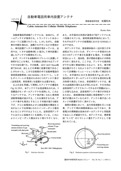
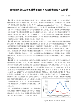
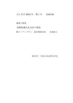
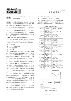
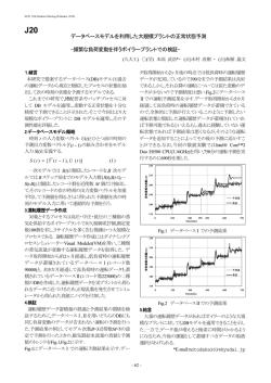
108-78916
Product Specification
製品規格
23 AUG 2012 Rev A
0.4mm pitch Board to Board connector H0.98
1.1 Scope :
1.1. 適用範囲
1.1
1.1
1.1 内容
1.1 Contents
本規格は0.4mmピッチ 基板間コネクタ ハイト0.98mmタ
This specification covers the requirements for
イプの製品性能、試験方法、品質保証の必要条件を規
product performance, test methods and quality
定している。
assurance provisions of 0.4mm pitch Board to
適用製品名と型番はFig.1の通りである。
Board connector height 0.98mm type.
Applicable product description and part numbers
are as shown in Fig.1.
2. Applicable Documents:
2. 参考規格類
以下規格類は本規格中で規定する範囲内に於いて、本
規格の一部を構成する。万一本規格と製品図面の間に
不一致が生じた時は、製品図面を優先して適用するこ
と。万一本規格と参考規格類の間に不一致が生じた時
は、本規格を優先して適用すること。
2.1 TE 規格
A.
109-5000
B.
501-78512
The following documents form a part of this
specification to the extent specified herein. In
the event of conflict between the requirements of
this specification and the product drawing, the
product drawing shall take precedence. In the
event of conflict between the requirements of
this specification and the referenced documents,
this specification shall take precedence.
2.1
: 試験法の一般条件
:
A.
TE Specifications :
109-5000
:Test Specification,
認定試験報告書
General Requirements for
Test Methods
B.
2.2 民間団体規格
A.
MIL-STD-202
:
電子電気部品の試験方法
B.
EIAJ(日本電子機械工業会) RCX-0102/101,102
:Qualification Test Report
2.2
Commercial Standards and Specifications
A.
MIL-STD-202 Test Method for Electronic and
Electrical Component Parts
B.
表面実装部品
501-78512
Electronic Indusries Association of Japan
RCX-0102/101,102
Test
Method
of
Surface
Mounting Devices soldering
©2012 Tyco Electronics Japan G.K.,
a TE Connectivity Ltd. Company
All Rights Reserved
TE logo is a trademark.
* Trademark
タイコエレクトロニクス ジャパン合同会社、TE Connectivity Ltd. グループ
Other products, logos, and company names might be trademarks of their respective owners.
1 of 10
LOC B
Product Specification
製品規格
108-78916
3. Requirements :
3. 一般必要条件
3.1
設計と構造
3.1 Design and Construction :
製品は該当製品図面に規定された設計、構造、物理
的寸法をもって製造されていること。
Product shall be manufactured based on the design,
construction and physical dimensions as specified
on the applicable product drawing.
3.2 材
A.
3.2 Materials
料
A.
コンタクト:りん青銅
Nickel plating 0.65μm Min (under)
ニッケルめっき 0.65μm 以上(下地)
金めっき 0.1μm 以上(接点部)
金めっき 0.05μm 以上(タイン部)
B.
Au plating 0.1μm Min (Contact area)
Au plating 0.05μm Min (Tine area)
補強金具: ステンレス鋼
B.
ニッケルめっき 0.65μm 以上(下地)
すずめっき 2.0~5.0μm(全面)
C.
Sn plating 2.0-5.0μm (All over)
C
定 格
A.
定格電圧 30 VAC
B.
定格電流 0.3 A
C.
使用温度範囲
-40 °C~ 85 °C
性能必要条件と試験方法
製品は Fig. 1 に規定された電気的、機械的、及び
耐環境的性能必要条件に合致するよう設計されてい
ること。試験は特別に規定されない限り室温下で行
われること。
Rev A
Housing: LCP, UL94V-0, Black
Ratings :
A. Voltage Rating :30 VAC
B. Current Rating :0.3 A
(通電による温度上昇を含む。)
3.4
C.
3.3
実効値
Peg: Phosphor Bronze
Nickel plating 0.65μm Min (under)
絶縁ケース: LCP、UL94V-0、黒色
3.3
Contact: Phosphor Bronze
C. Temperature Rating :
-40 °C to 85 °C
The upper limit of the temperature includes
the temperature rising resulted by the
energized electrical current.
3.4 Performance Requirements and Test
Descriptions :
The product shall be designed to meet the
electrical, mechanical and environmental
performance requirements specified in Fig.1.
All tests shall be performed in the room
temperature, unless otherwise specified.
2 of 10
Product Specification
製品規格
108-78916
3.5 性能必要条件と試験方法の要約
3.5 Test Requirements and Procedures Summary
項目
試験項目
Para.
3.5.1
3.5.1
Test
規
Items
製品の確認
Examination of Product
格
値
試
Requirements
験
方
法
Procedures
製品図面の必要条件に合致して
目視により、コネクタの機能上支障をき
いること。
たす損傷を検査する。
Meets the requirements of
Visual inspection
product drawing.
No physical damage
電
気
的
性
能
Electrical Requirements
3.5.2
総合抵抗
70 mΩ 以下
(ローレベル)
ハウジングに組み込まれ嵌合したコンタ
クトを開路電圧 20 mV 以下、閉路電流
10 mA 以下の条件で測定する。
Fig.4参照
3.5.2
Termination Resistance
70 mΩ Max.
(Low Level)
Mated connectors on PCB
Measure-device: Open circuit 20mV Max
Mesh currents 10 mA.
Refer to Fig.4
3.5.3
絶縁抵抗
100 MΩ 以上
100 V DC ±10% 1分間印加。
嵌合したコネクタの
隣接コンタクト間で測定する。
EIA 364-21C
3.5.3
Insulation Resistance
100 MΩMin.
Impresse voltage 100 V DC ±10% for
1minute
Test between adjacent circuits of
mated
connectors.
EIA 364-21C
3.5.4
耐電圧
沿面放電、フラッシュオーバー
200 VAC
1 分間印加
等がないこと。
コネクタ嵌合あり
漏洩電流 0.5 mA 以下
隣接コンタクト間で測定する。
EIA 364-20B 条件Ⅰ
3.5.4
Dielectric withstanding
No creeping discharge nor
200 VAC for 1 minute.
Voltage
flashover shall occur.
Test between adjacent circuits of
Current leakage : 0.5 mA
mated
Max.
EIA 364-20B ConditionⅠ
connectors.
Fig.1 (To be continued)
Rev A
3 of 10
Product Specification
製品規格
108-78916
項目
試験項目
Para.
3.5.5
Test
規
Items
温度上昇
格
値
試
験
Requirements
方
法
Procedures
定格電流を通電して、温度上昇
通電による温度上昇を測定する。
は 30 °C 以下
(タイン部を測定)
EIA-364-70A
3.5.5
Temperature Rising
30 °C Max. under loaded
Measure temperature rising by energized
current rating.
current.(measure tine)
EIA-364-70A
機
械
的
性
能
Mechanical Requirements
3.5.6
振動
振動中 1 μsec. をこえる不連
嵌合したコネクタに 1.52 mm の振幅で、
(低周波)
続導通を生じないこと。
10-55-10 Hz に毎分 1 サイクルの割合で変
100 mΩ 以下(終期)
化する掃引振動を直交する三方向軸に 2 時
間ずつ与える。Fig.5参照
EIA 364-28D
3.5.6
Vibration
No electrical discontinuity
Vibrates mated connectors
(Low Frequency)
greater than 1 μsec. shall
Frequency range: 10-55-10 Hz
occur.
Amplitude: 1.52 mm
100 mΩ Max. (Final)
Time: 2 hours each of 3 direction (XYZ)
Refer to Fig.5
EIA 364-28D
3.5.7
衝撃
衝撃により 1 μsec. をこえる
加速度:490m/s2(50 G)、接続時間:11 m
不連続導通を生じないこと。
sec.
100 mΩ 以下(終期)
衝撃パルス波形
: 半波正弦波
速度変化
:
3.44 m/s
衝撃回数
:
X, Y, Z 軸正逆方向に
各3 回宛、合計 18 回
MIL-STD-202
3.5.7
Physical Shock
Fig.5参照
試験法213,条件A
No electrical discontinuity
Accelerated Velocity : 50 G
greater than 1 μsec. shall occur.
Waveform
: Halfsine shock pluses
100 mΩ Max. (Final)
Duration
: 11 m sec.
Velocity Change
: 3.44 m/s
Number of Drops
: 3 drops each
both directions (XYZ) totally 18 drops.
Refer to Fig.5
MIL-STD-202 Test method213,conditionA
Fig.1 (To be continued)
Rev A
4 of 10
Product Specification
製品規格
108-78916
項目
試験項目
Para.
3.5.8
Test
規
Items
格
値
試
Requirements
験
方
法
Procedures
コネクタ挿入力
挿入力:1.3N/pin Max.
コネクタ・アッセンブリを30回挿入⇔引抜
引抜力
引抜力:0.15N/pin Min.
する。この時の挿入力及び引抜力を測定す
る。(初回、30回)
操作速度:2mm/min.
3.5.8
Connector Mating Force
Unmating Force
Mating Force: 1.3N/pin Max.
Mate and unmate connectors for 30
Unmating Force: 0.15N/pin Min.
times. Measure the
mate/unmate force
(initial,30 times)
Operation Speed:2mm/min.
3.5.9
耐久性
100 mΩ 以下(終期)
(繰り返し挿抜)
3.5.9
挿抜速度 2mm/min
挿抜回数 30 回
Durability
Termination Resistance
Mate and unmate connectors for 30 times
(Repeated Mate /
100 mΩ Max. (Final)
Operation Speed : 2mm/min
はんだ浸漬面積の95%以上がは
はんだ温度:230℃±5℃
んだで濡れていること。
はんだ浸漬時間:3±0.5sec
Unmating)
3.5.10
はんだ付け性
使用フラックス:アルファ100
3.5.10
Solderability
WetSolder Coverage:95% Min.
Reflow connectors
Solder Temperature:230℃±5℃
Immersion Duration:3±0.5sec
Flux : Alpha 100
3.5.11
はんだ耐熱性
ハウジングの変形、溶け出しが
リフローソルダリングの場合
無く、物理的損傷を生じないこ
プリント基板に取り付けて評価する。
と。
予熱
140~170℃:90±30秒
加熱
230℃以上:40±10秒
ピーク温度:255℃以下
Fig.6
3.5.11
参照
Resistance to Soldering
Tested housing shall show no
Reflow connectors
Heat
evidevce of deformation,
Test connector on PCB.
fusion of housing and no
Pre-Heat 140~170℃ : 90±30sec.
physical damage.
Heat 230℃ Min. : 40±10sec.
Heat Peak 255℃Max. Refer to Fig.6
Fig.1 (To be continued)
Rev A
5 of 10
Product Specification
製品規格
108-78916
環
境
的
性
能
Environmental Requirements
項目
試験項目
Para.
3.5.12
Test
Items
熱衝撃
規
格
値
試
Requirements
100 mΩ 以下(終期)
験
方
法
Procedures
嵌合したコネクタを
-55°C / 30 分、85°C / 30 分
これを 1 サイクルとし、試験槽に5サイク
ル放置する。
EIA 364-32C
3.5.12
Thermal Shock
100 mΩ Max. (Final)
Mated connector
1 cycle:-55°C / 30 min.,85°C / 30 min.
repeat 5 cycles.
EIA 364-32C
3.5.13
耐湿性
絶縁抵抗 100 MΩ 以上 (終期)
嵌合したコネクタを
(定常状態)
100 mΩ 以下(終期)
90~95 %
R.H.、40°C±2℃の試験槽に96時
間放置する。
EIA 364-31B
3.5.13
3.5.14
Humidity
Insulation resistance
Mated connector
(Steady State)
100 MΩ Min. (Final)
90~95 %
Termination Resistance
96hours
100 mΩ Max. (Final)
EIA 364-31B
100 mΩ 以下(終期)
嵌合したコネクタを
温度寿命(耐熱)
R.H. 40°C±2℃
85℃±2℃の試験槽に96時間放置する。
EIA 364-17B
3.5.14
Temperature Life
100 mΩ Max. (Final)
Mated connector
85 °C±2°C, 96 hours
(Heat Aging)
EIA 364-17B
Fig.1 (To be continued)
Rev A
6 of 10
Product Specification
製品規格
108-78916
項目
試験項目
Para.
3.5.15
Test
規
Items
耐寒性
格
値
試
験
Requirements
100 mΩ 以下(終期)
方
法
Procedures
嵌合したコネクタを
-40°C±3°Cの試験槽に96時間放置する。
(25℃で2h放置後LLCR測定)
3.5.15
Resistance to Cold
100 mΩ Max. (Final)
Mated connector
-40 °C±3°C
96 hours
(Keep 25℃ for 2hours before measuring
LLCR)
3.5.16
温湿度サイクル
絶縁抵抗
100MΩ 以上(終期)
嵌合した状態のコネクタにおいて
100 mΩ 以下 (終期)
25~65℃、80~96%R.H.
接触部に酸化物や腐食物がない
-10℃寒冷衝撃あり
こと。
24時間を1サイクルとして10サイクル行う
EIA 364-31 (Fig.7)
3.5.16
Humidity
Insulation resistance
Mated connector,
Temperature Cycling
100MΩ Min.(Final)
25~65℃, 80~96% R.H.
100 mΩ Max. (Final)
Cold shock -10℃ performed.
No corrosion on the contact
1 cycle: 24hour
area.
Repeat 10 cycles.
No visible oxidation on the
EIA 364-31 (Fig.7)
contact area.
3.5.17
耐 SO2ガス性
100 mΩ Max. (終期)
嵌合したコネクタを SO2ガス濃度10±3ppm,
接触部に腐食物がないこと。
温度25℃,湿度75%以上の試験環境下に48時
間さらすこと。
3.5.17
SO2 GAS
100 mΩ Max. (Final)
Mated connectors
No corrosion on the contact
Sulfurous acid gas:10±3ppm
area.
Temperature 25℃ and 75% R.H.
Time: 48 hours.
Fig.1 (End)
Rev A
7 of 10
Product Specification
製品規格
108-78916
3-6 製品認定試験の試験順序
Product Qualification Test Sequence
試験項目
製品の確認検査
総合抵抗 (ローレベル)
絶縁抵抗
耐電圧
温度上昇
振動 (低周波)
衝撃
コネクタ挿抜力
耐久性 (繰り返し挿抜)
はんだ付け性
はんだ耐熱性
熱衝撃
耐湿性 (定常状態)
温度寿命(耐熱)
耐寒性
温湿度サイクル
耐 SO2 ガス性
Test Examination
Examination of
product
Termination
Resistance
(Low Level)
Insulation
Resistance
Dielectric
withstanding Voltage
Temperature Rising
Vibration (Low
Frequency)
Physical Shock
Connector
Mateing/Unmating
Force
Durability
(Repeated
Mate/Unmating)
Solderability
Resistance to
Soldering Heat
Thermal Shock
Humidity (Steady
State)
Temperature Life
(Heat Aging)
Resistance to Cold
Humidity,
Temperature Cycling
Sulfurous Acid Gas
Resistivity
1
2
3
4
5
1
1,3
1,5
1,5
1,6
2,4
2.4
2,5
Test Group
6
7
8
Test Sequence (a)
1,3
1,3
9
10
11
12
13
1,5
1,5
1,5
1,5
1,5
1,5
2,4
2,4
2,4
2,4
2,4
2,4
2
3
2
3
3
3
4
2
2
3
3
3
3
3
3
欄内の数字は試験の順序を示す。/Numbers indicate sequence in which the tests are performed.
Fig.2
Rev A
8 of 10
Product Specification
製品規格
108-78916
4. 製品保証条項
4.1製品認定試験
A. 試料の選定
コネクタとコンタクトは該当する取り扱い説
明書に従って、準備されること。試料は現行
の生産システムから無作為抽出で選定される
こと。
4. Quality Assurance Provisions
4.1 Qualification Testing
A. Sample Selection
Connector and contact shall be prepared
in accordance with applicable
Instruction Sheets. They shall be
selected at random from current
production.
Product Part No.
Products name
1-2201196-0
Plug Assembly 10pos
1-2201197-0
Rec. Assembly 10pos
2-2201196-4
Plug Assembly 24pos
2-2201197-4
Rec. Assembly 24pos
3-2201196-0
Plug Assembly 30pos
3-2201197-0
Rec. Assembly 30pos
Mating Height(mm)
0.98
Fig.3 対象製品型番
Part Number
Fig.4 ローレベル総合抵抗測定方法
Method of Termination Resistance Measuring
Fig.5 コネクタ固定方法
Method of Connector Mounting for Vibration and shock
Rev A
9 of 10
Product Specification
製品規格
108-78916
Fig.6 リフロー耐熱性の温度プロファイル
Temperature Profile of Reflow Resistance solder heat
Fig.7 温湿度サイクル
Humidity Temperature Cycling
Rev A
10 of 10
© Copyright 2026 Paperzz