Statistical Approach to Multipitch Analysis
(統計的手法による多重音解析に関する研究)
Hirokazu Kameoka
亀岡 弘和
Contents
Chapter 1
Introduction
1
1.1
Background . . . . . . . . . . . . . . . . . . . . . . . . . . . . . . . . . . . .
1
1.2
Source Separation and F0 Estimation . . . . . . . . . . . . . . . . . . . . . .
2
1.3
Estimating the Number of Sources
. . . . . . . . . . . . . . . . . . . . . . .
3
1.4
Temporal and Spectral Continuity . . . . . . . . . . . . . . . . . . . . . . . .
4
1.5
Objective of the Thesis . . . . . . . . . . . . . . . . . . . . . . . . . . . . . .
5
Chapter 2
Harmonic Clustering
6
2.1
Introduction . . . . . . . . . . . . . . . . . . . . . . . . . . . . . . . . . . . .
6
2.2
Principle . . . . . . . . . . . . . . . . . . . . . . . . . . . . . . . . . . . . . .
7
2.2.1
Binary Masking of Power Spectrum Based on Sparseness . . . . . . .
7
2.2.2
Single-Tone Frequency Estimation . . . . . . . . . . . . . . . . . . . .
7
2.2.3
Single-Voice F0 Estimation and Overtone Separation . . . . . . . . .
8
2.2.4
Multipitch Estimation and Source Separation . . . . . . . . . . . . .
10
Bayesian Harmonic Clustering
12
Chapter 3
3.1
Introduction . . . . . . . . . . . . . . . . . . . . . . . . . . . . . . . . . . . .
12
3.2
Spectral Cluster Model . . . . . . . . . . . . . . . . . . . . . . . . . . . . . .
13
3.2.1
Definition of Fourier Transform Pair . . . . . . . . . . . . . . . . . .
13
3.2.2
Definition of Analytic Signal . . . . . . . . . . . . . . . . . . . . . . .
13
3.2.3
Gabor Transform Output of Periodic Signal Model . . . . . . . . . .
13
3.2.4
Constant Q Filterbank Output of Periodic Signal Model . . . . . . .
15
Principle . . . . . . . . . . . . . . . . . . . . . . . . . . . . . . . . . . . . . .
17
3.3.1
Optimal Separation of Power Spectrum . . . . . . . . . . . . . . . . .
17
3.3.2
Minimization of Distortion Measure . . . . . . . . . . . . . . . . . . .
20
3.3.3
Iterative Maximum Likelihood Estimation . . . . . . . . . . . . . . .
22
Bayesian Harmonic Clustering . . . . . . . . . . . . . . . . . . . . . . . . . .
27
3.4.1
27
3.3
3.4
Maximum A Posteriori (MAP) Estimation . . . . . . . . . . . . . . .
i
3.5
3.6
3.7
3.4.2
Smoothness of Spectral Envelope . . . . . . . . . . . . . . . . . . . .
28
3.4.3
Update Equations for the Model Parameters . . . . . . . . . . . . . .
29
A Criterion for Source Number Estimation . . . . . . . . . . . . . . . . . . .
30
3.5.1
Model Selection using Bayesian Information Criterion . . . . . . . . .
30
3.5.2
Model Selection Algorithm . . . . . . . . . . . . . . . . . . . . . . . .
33
Experimental Evaluation . . . . . . . . . . . . . . . . . . . . . . . . . . . . .
33
3.6.1
Condition . . . . . . . . . . . . . . . . . . . . . . . . . . . . . . . . .
33
3.6.2
Results . . . . . . . . . . . . . . . . . . . . . . . . . . . . . . . . . . .
35
Summary of Chapter 3 . . . . . . . . . . . . . . . . . . . . . . . . . . . . . .
36
Chapter 4
Harmonic-Temporal Clustering
41
4.1
Introduction . . . . . . . . . . . . . . . . . . . . . . . . . . . . . . . . . . . .
41
4.2
Abstract and Organization of Chapter 4 . . . . . . . . . . . . . . . . . . . .
43
4.3
Spectro-Temporal Cluster Model . . . . . . . . . . . . . . . . . . . . . . . .
43
4.3.1
Constant Q Filterbank Output of Pseudoperiodic Signal . . . . . . .
43
4.3.2
Nonparametric and Parametric Modeling . . . . . . . . . . . . . . . .
45
4.3.3
Parametric Spectro-Temporal Cluster Model . . . . . . . . . . . . . .
46
Optimal Clustering Algorithm . . . . . . . . . . . . . . . . . . . . . . . . . .
49
4.4.1
Nonparametric HTC . . . . . . . . . . . . . . . . . . . . . . . . . . .
49
4.4.2
Parametric HTC . . . . . . . . . . . . . . . . . . . . . . . . . . . . .
52
Bayesian HTC . . . . . . . . . . . . . . . . . . . . . . . . . . . . . . . . . . .
56
4.5.1
Reformulation . . . . . . . . . . . . . . . . . . . . . . . . . . . . . . .
56
4.5.2
Prior Distribution . . . . . . . . . . . . . . . . . . . . . . . . . . . . .
58
Experimental Evaluation . . . . . . . . . . . . . . . . . . . . . . . . . . . . .
60
4.6.1
Note Estimation from Acoustic Signals of Music . . . . . . . . . . . .
60
4.6.2
F0 Determination of Single Speech in Clean Environment . . . . . . .
65
4.6.3
Multipitch Estimation of Concurrent Speech . . . . . . . . . . . . . .
69
Summary of Chapter 4 . . . . . . . . . . . . . . . . . . . . . . . . . . . . . .
71
4.4
4.5
4.6
4.7
Chapter 5
Joint Estimation of Spectral Envelope and Fine Structure
74
5.1
Introduction . . . . . . . . . . . . . . . . . . . . . . . . . . . . . . . . . . . .
74
5.2
Formulation of the Proposed Method . . . . . . . . . . . . . . . . . . . . . .
77
5.2.1
77
Speech Spectrum Modeling . . . . . . . . . . . . . . . . . . . . . . . .
ii
5.2.2
5.3
5.4
Parameter Optimization . . . . . . . . . . . . . . . . . . . . . . . . .
80
Experimental Evaluations . . . . . . . . . . . . . . . . . . . . . . . . . . . .
83
5.3.1
Single Voice F0 Determination . . . . . . . . . . . . . . . . . . . . . .
83
5.3.2
Synthesis and Analysis . . . . . . . . . . . . . . . . . . . . . . . . . .
85
5.3.3
Analysis and Synthesis . . . . . . . . . . . . . . . . . . . . . . . . . .
87
Summary of Chapter 5 . . . . . . . . . . . . . . . . . . . . . . . . . . . . . .
89
Chapter 6
Parameter Optimization of Sinusoidal Signal Model
92
6.1
Introduction . . . . . . . . . . . . . . . . . . . . . . . . . . . . . . . . . . . .
92
6.2
Abstract and Organization of Chapter 6 . . . . . . . . . . . . . . . . . . . .
95
6.3
Problem Setting . . . . . . . . . . . . . . . . . . . . . . . . . . . . . . . . . .
96
6.3.1
Pseudoperiodic Signal Model . . . . . . . . . . . . . . . . . . . . . . .
96
6.3.2
Objective Function Defined on Gabor Transform Domain . . . . . . .
97
Parameter Optimization Algorithm . . . . . . . . . . . . . . . . . . . . . . .
99
6.4.1
Auxiliary Function Method . . . . . . . . . . . . . . . . . . . . . . .
99
6.4.2
Inequality for L2 norm . . . . . . . . . . . . . . . . . . . . . . . . . . 101
6.4.3
Theorem on Differentiable Concave Functions . . . . . . . . . . . . . 103
6.4.4
Update Equations for Sinusoidal Parameters . . . . . . . . . . . . . . 105
6.4.5
Overview of the Algorithm . . . . . . . . . . . . . . . . . . . . . . . . 106
6.4
6.5
6.6
Experimental Evaluation . . . . . . . . . . . . . . . . . . . . . . . . . . . . . 107
6.5.1
Convergence Properties of the Algorithm . . . . . . . . . . . . . . . . 107
6.5.2
1ch Blind Source Separation of Concurrent Speech . . . . . . . . . . . 108
Summary of Chapter 6 . . . . . . . . . . . . . . . . . . . . . . . . . . . . . . 110
Chapter 7
Conclusion
113
Acknowledgement (in Japanese)
115
References
120
Appendix A List of Publications
131
Appendix B Awards Received
138
iii
Abstract
We deal through this paper with the problem of estimating “information” of each sound
source separately from an acoustic signal of compound sound. Here “information” is used in
a wide sense to include not only the waveform itself of the separate source signal but also the
power spectrum, fundamental frequency (F0 ), spectral envelope and other features. Such a
technique could be potentially useful for a wide range of applications such as robot auditory
sensor, robust speech recognition, automatic transcription of music, waveform encoding for
the audio CODEC (compression-decompression) system, a new equalizer system enabling
bass and treble controls for separate source, and indexing of music for music retrieval system.
Generally speaking, if the compound signal were separated, then it would be a simple
matter to obtain an F0 estimate from each stream using a single voice F0 estimation method
and, on the other hand, if the F0 s were known in advance, could be very useful information
available for separation algorithms. Therefore, source separation and F0 estimation are
essentially a “chicken-and-egg problem”, and it is thus perhaps better if one could formulate
these two tasks as a joint optimization problem. In Chapter 2, we introduce a method called
“Harmonic Clustering”, which searches for the optimal spectral masking function and the
optimal F0 estimate for each source by performing the source separation step and the F0
estimation step iteratively.
In Chapter 3, we establish a generalized principle of Harmonic Clustering by showing that
Harmonic Clustering can be understood as the minimization of the distortion between the
power spectrum of the mixed sound and a mixture of spectral cluster models. Based on this
fact, it becomes clear that this problem amounts to a maximum likelihood problem with
the continuous Poisson distribution as the likelihood function. This Bayesian reformulation
enables us not only to impose empirical constraints, which are usually necessary for any
underdetermined problems, to the parameters by introducing prior probabilities but also
to derive a model selection criterion, that leads to estimating the number of sources. We
confirmed through the experiments the effectiveness of the two techniques introduced in this
chapter: multiple F0 estimation and source number estimation.
iv
Human listeners are able to concentrate on listening to a target sound without difficulty
even in the situation where many speakers are talking at the same time or many instruments
are played together. Recent efforts are being directed toward the attempt to implement this
ability by human called the “auditory stream segregation”. Such an approach is referred to as
the “Computational Auditory Scene Analysis (CASA)”. In Chapter 4, we aim at developing
a computational algorithm enabling the decomposition of the time-frequency components
of the signal of interest into distinct clusters such that each of them is associated with a
single auditory stream. To do so, we directly model a spectro-temporal model whose shape
can be taken freely within the constraint called “Bregman’s grouping cues”, and then try
to fit the mixture of this model to the observed spectrogram as well as possible. We call
this approach “Harmonic-Temporal Clustering”. While most of the conventional methods
usually perform separately the extraction of the instantaneous features at each discrete time
point and the estimation of the whole tracks of these features, the method described in
this chapter performs these procedures simultaneously. We confirmed the advantage of the
proposed method over conventional methods through experimental evaluations.
Although many efforts have been devoted to both F0 estimation and spectral envelope
estimation intensively in the speech processing area, the problem of determining F0 and
spectral envelope seems to have been tackled independently. If the F0 were known in advance,
then the spectral envelope could be estimated very reliably. On the other hand, if the
spectral envelope were known in advance, then we could easily correct subharmonic errors.
F0 estimation and spectral envelope estimation, having such a chicken and egg relationship,
should thus be done jointly rather than independently with successive procedures. From this
standpoint, we will propose a new speech analyzer that jointly estimates pitch and spectral
envelope using a parametric speech source-filter model. We found through the experiments
a significant advantage of jointly estimating F0 and spectral envelope in both F0 estimation
and spectral envelope estimation.
The approaches of the preceding chapters are based on the approximate assumption of
additivity of the power spectra (neglecting the terms corresponding to interferences between
frequency components), but it becomes usually difficult to infer F0 s when two voices are
mixed with close F0 s as far as we are only looking at the power spectrum. In this case not
only the harmonic structure but also the phase difference of each signal becomes an important
cue for separation. Moreover, having in mind future source separation methods designed for
multi-channel signals of multiple sensory input, analysis methods in the complex spectrum
v
domain including the phase estimation are indispensable. Taking into account the significant
effectiveness and the advantage of the approach described in the preceding chapters, we
have been motivated to extend it to a complex-spectrum-domain approach without losing
its essential characteristics. The main topic of Chapter 6 is the development of a nonlinear
optimization algorithm to obtain the maximum likelihood parameter of the superimposed
periodic signal model: focusing on the fact that the difficulty of the single tone frequency
estimation or the fundamental frequency estimation, which are at the core of the parameter
estimation problem for the sinusoidal signal model, comes essentially from the nonlinearity
of the model in the frequency parameter, we introduce a new iterative estimation algorithm
using a principle called the “auxiliary function method”. This idea was inspired by the
principle of the EM algorithm. Through simulations, we confirmed that the advantage of
the proposed method over the existing gradient descent-based method in the ability to avoid
local solutions and the convergence speed. We also confirmed the basic performance of our
method through 1ch speech separation experiments on real speech signal.
vi
Abstract in Japanese
本研究は、様々な音が混在する中で目的音の情報(基本周波数やスペクトル包絡など)を
分離推定する多重音解析技術を提案するものである。多重音解析技術は実用性が高く、ロボッ
ト聴覚、知能的音響センサ、音声認識、音源分離、自動採譜、オーディオコーデックの効率
的な符号化機能、楽音ごとにイコライズできる高自由度イコライザ、音楽コンテンツの自動
メタデータ化とそれによる多種機能つき音楽検索システムなど、実に広範囲にわたるアプリ
ケーションへの応用が期待される。
多重音中の各音源の基本周波数は、各音源のスペクトルが既知であれば、高い精度で推定
できる。一方で、多重音スペクトルは、各音源の基本周波数が既知であれば高い精度で分離
できうる。このことから分かるように、多重音スペクトル分離と基本周波数推定の問題はい
わゆる「鶏と卵の関係」にある。従って、多重音スペクトルを音源ごとに分解することと各
音源の基本周波数は同時最適化問題として解かれるべきであると我々は考えた。そこで、第
2 章では、音源分離と基本周波数推定を同時最適化問題として定式化し、対象とする混合音
のパワースペクトルを音源ごとに対応するようにクラスタ化する分配関数 (バイナリマスク)
と、各音源の基本周波数を最適推定する原理を提案する。この最適解探索は音源分離ステッ
プと基本周波数ステップの反復計算により行うことができ、この方法を調波構造化クラスタ
リングと呼ぶ。
第 3 章では、調波構造化クラスタリングの原理を一般化したのちに、これをベイズ的枠組
で別解釈および再定式化を行う。その結果から、調波構造化クラスタリングはパラメトリッ
クな調波構造モデルの重ね合わせによる観測スペクトルの最適フィッティングであるという
解釈ができること、この解釈に基づきさらにはモデル構造選択規準により音源数を推定する
ための規準が作れることが示される。評価実験により、本章で提案した 2 つの要素技術であ
る、調波構造化クラスタリングによる多重ピッチ推定法と音源数自動決定法の有効性がいず
れも示された。
人間の聴覚機能を計算機で実現しようという試みが活発に進められており、その枠組を総
称して計算論的聴覚情景分析 (Computational Auditory Scene Analysis: CASA) と呼ぶ。近
年この研究分野における興味の対象は、Bregman が指摘した音脈 (人間がひとまとまりと知
覚する音の流れ) が形成されるための条件 (分凝要件) に基づく混合音分離法の実現にある。
vii
第 4 章では、入力された音響信号の時間周波数成分を音脈に対応する時間周波数成分に分解
する問題を定式化する。第 4 章で提案する調波時間構造化クラスタリングのアイディアの要
点は、Bregman の分凝要件から逸脱しない範囲の自由度をもった時変スペクトルを直接的に
モデル化し、これを混合したもので対象の時変スペクトルを説明しようとすることである。
各時刻で独立に調波成分を見つけ出すための処理 (周波数方向の群化) と、抽出された調波成
分特徴量の時系列を時間方向にスムージングする処理 (時間方向の群化) を多段処理的に行
う多くの従来法に対し、調波時間構造化クラスタリングは、これらを協調し合う同時最適化
問題として定式化したものに相当し、個々の音源の時間周波数全域に渡ったパワースペクト
ル構造を一挙に推定できる新しい方法論である。評価実験により、混合音声信号および音楽
音響信号の基本周波数推定精度が、それぞれの分野における最先端の従来法を上回ることを
確認した。
第 5 章では、従来まで独立な問題として扱われがちであったスペクトル包絡推定と基本周
波数推定は本来相補関係にあるべきとの問題意識のもと、これらを同時最適化問題として定
式化し、個々の音源のスペクトル包絡推定も同時に行える多重音解析法への応用可能性を示
した。また、単一話者音声を対象としたピッチ推定、合成分析、分析合成に関する各評価実
験を通して、提案法のようにピッチ周波数とスペクトル包絡を同時推定することがいずれの
推定の精度に対しても良い効果をもたらしたことを確認した。
第 5 章までの手法は、パワースペクトルの加法性が近似的に成り立つ (周波数成分間の干
渉項を無視できる) という仮定のもとで、観測パワースペクトルから所望の情報を得るため
のアプローチであった。しかし、2 音以上の近接する基本周波数の分離推定や、近接周波数
成分の分離を高精度に行うためには、調波構造だけでなく各信号の位相差が分離の手がかり
になる。さらに、将来的に複数センサ入力の多チャンネル信号を対象とした音源分離手法を
視野に入れるのであれば、位相推定を含んだ複素スペクトル領域での解析が不可欠である。
第 5 章までの方法論の有効性と上記のような展望を踏まえ、第 6 章では、第 3 章のアプロー
チをその本質を損なうことなく複素スペクトル領域に拡張できないかということがテーマで
あり、中心的な議論の対象は、周期信号重畳モデルの最尤パラメータを求めるための非線形
最適化アルゴリズムを開発することである。そこで、正弦波重畳モデルのパラメータ推定問
題の核である周波数推定ないし基本周波数推定の難しさの本質が、正弦波重畳モデルが周波
数パラメータに関して非線形である点にあることに着目し、補助関数を用いた新しい反復推
定アルゴリズムを導く。この考え方は、EM アルゴリズムのヒントにして着想したものであ
る。シミュレーション実験により、第 6 章で提案するパラメータ最適化アルゴリズムは勾配
法を用いる多数の従来法よりも局所解回避能力と収束速度の面で優れていることを示した。
また、実音声を用いた 1 チャネル混合音声分離実験を行い、提案法の基本性能を確認した。
viii
Chapter 1
Introduction
1.1
Background
We deal through this paper with the problem of estimating “information” of each sound
source separately from an acoustic signal of concurrent sound sources. The acoustic signal
can be the compound sound of several people speaking at the same time, or several musical
instruments playing together. Here “information” is used in a wide sense to include not only
the waveform itself of the separate source signal but also the power spectrum, fundamental
frequency (F0 ), spectral envelope and other features. Such a technique could be potentially useful for a wide range of applications such as robot auditory sensor, robust speech
recognition, automatic transcription of music, waveform encoding for the audio CODEC
(compression-decompression) system, a new equalizer system enabling bass and treble controls for separate source, and indexing of music for music retrieval system. The problem,
however, is not so simple to solve. We will henceforth call this kind of problem “multisource
analysis”. Multisource analysis can be categorized in several types of problem setting depending on the situation one assumes. A situation where there are more sensors than source
signals, for instance, is referred to as the overdetermined case, in which the source separation can be performed satisfactorily especially in clean environment by using the well-known
“Independent Component Analysis” (see, for example, [46, 47]). A situation where there are
less sensors than source signals, on the other hand, is referred to as the underdetermined
case. In such a situation, one requires some empirical assumption in addition to the statistical independence of sources. One of the most well-known such assumptions is called the
“time-frequency sparseness of speech”, which assumes that time-frequency components of
sources rarely overlap with each other. This assumption is experimentally supported by the
1
2
Chapter 1 Introduction
methods that use a binary mask to extract only the time-frequency components which seems
to have propagated from the same spatial direction (or position) [117, 91, 92, 8].
On the contrary, the particular problem of interest in this paper is a multisource analysis
where one only has a single sensory input and does not know how many sources in the
compound acoustic signal. We will be confronted with such a situation, for example, when
we need to detect musical note from monaural CD recordings, or when several different
source signals originate from very close position even if we had multiple sensors. The greatest
difference from the multisensor case is thus that it is impossible to obtain spatial data of
sources.
1.2
Source Separation and F0 Estimation
The auditory system is able to extract the period despite very different waveforms or
spectra of sounds at the ears. Explanations of how this is done have been elaborated since
antiquity [27]. Even with a monaural recording, a musically inclined listener can often follow
and concentrate on the particular melodic line of each instrument in a polyphonic ensemble.
This implies that human can hear several pitches from a single compound waveform. As
psychophysical data on this capability are said to be fragmentary (see, for example, [12,
13, 51]), the limits of this capability, and the parameters that determine them, are not well
known. This “proof of feasibility” has nevertheless encouraged the search for algorithms
for multisource analysis. The task of multisource analysis in essence involves two tasks:
source separation and F0 estimation. If the compound signal representing the mixture were
separated into single source signals, then it would be a simple matter to derive an F0 estimate
from each stream using a single voice F0 estimation algorithm (comprehensive reviews for
single voice F0 estimation methods can be seen in [49, 50]). On the other hand the F0 s, if
known in advance, could be very useful information available for separation algorithms. This
leads to a “chicken and egg” situation: estimation and segregation are each a prerequisite of
the other, the difficulty being to “bootstrap” this process.
Conventional techniques for multisource analysis are usually designed to cope with either
of the two tasks, F0 (multipitch) estimation and source separation. Many publications on
methods corresponding to the former type have been proposed [111, 101, 59, 105, 38, 79, 60,
61, 116, 45, 10, 32, 43, 66, 67, 69, 102, 88, 89, 112, 107, 108, 75, 23, 24, 26, 72, 113, 114, 115,
22, 57], which can be found in de Cheveigné’s excellent review paper [28].
Chapter 1 Introduction
3
A learning-based method such like sparse coding [110], non-negative sparse coding [109,
2, 97], and non-negative matrix factorization [94] models the signal or power spectrum as
a weighted sum of basis functions and tries to estimate them such that each of them is a
waveform structure or a power spectrum structure that seems to recur many times in the
whole acoustic signals or spectrogram. This approach enables source separation without
estimating F0 s and thus corresponds to the latter type.
However, since source separation and F0 estimation, as is mentioned beforehand, are in
essence a “chicken and egg” problem, it is perhaps better if one could formulate these two
tasks as a joint optimization problem. In Chapter 2, a new principle called “Harmonic
Clustering” is introduced, which iteratively performs two steps: source separation and F0
estimation, in which the common objective function is decreased/increased monotonically
at each iteration step. This is reformulated in Chapter 3 in a Bayesian framework, which
enables further extensions.
1.3
Estimating the Number of Sources
Up to now, no concern was given to finding the number of sources present within a mixture.
This is a difficult aspect of multisource analysis. Many studies ignore it and concentrate on
the simpler task of producing some fixed number of estimates, regardless of the number of
sources.
Some signals are inherently ambiguous, and may be interpreted either as a single voice
with low F0 , or as the sum of several voices with higher, harmonically-related F0 s. Tuned to
find as many voices as possible (or to favor the shortest possible periods) an algorithm may
“dismember” a voice into subsets of partials, tuned to find as few as possible (or the longest
possible periods) it may coalesce multiple voices. The voice count is accordingly over- or
underestimated.
Iterative estimation methods typically apply a model at each iteration, and assign as much
signal power to a voice as fits this model. Iteration continues on the remainder, and stops
when the spectrum (or waveform) has been depleted of power. In the presence of noise, it
may be difficult to distinguish between residual noise and yet another source.
In the method of [26], cancellation filters are applied successively to remove each periodic
voice. The algorithm stops when application of a new filter reduces power by less than a
criterion ratio. Klapuri evaluates the “global weight” of the F0 candidate derived from the
4
Chapter 1 Introduction
residual after a voice has been suppressed, and stops the search if that weight falls below
threshold [67]. In nonnegative deconvolution [90, 95], the number of sources is given by the
number of elements of deconvolved matrix with amplitudes greater than some threshold. Wu
and colleagues [113, 114, 115] use an HMM to model transitions between states of 0, 1 or 2
voices.
The Bayesian formulation of the Harmonic Clustering enables us further to derive a theoretical framework for estimating the number of sources.
1.4
Temporal and Spectral Continuity
In general, there are two situations in which the multisource analysis becomes extremely
difficult to solve: One is when the F0 s of two or more sources coincide at a particular instant
of time, and the other is when the partials of one source overlap with those of other sources.
Are there any ways to make a reasonable guess for restoring the partial amplitudes of the
underlying sources in such situations? A hint for this apparently unsolvable question is the
temporal and spectral continuity of source signals.
A common assumption is that voices should change gradually over time. Continuity of
F0 contours is often exploited in so-called “post-processing” algorithms [49] such as mediansmoothing, dynamic programming, Kalman filtering [76, 106, 4], hidden Markov models
[113, 114, 115], or multiple agents [75, 45] in order to improve the F0 estimation results
obtained via some frame-by-frame F0 estimation algorithm. In addition to continuity of F0
tracks, the assumption that partial amplitudes vary smoothly can be used to track voices
over instants when F0 s cross. A challenge to the multisource analysis using the continuityconstraints of F0 and amplitude tracks is called the “Computational Auditory Scene Analysis
(CASA)”, which will be mentioned more in details in Chapter 4.
An assumption that has been used recently is spectral smoothness, that is, limited variation
of partial amplitudes across frequency axis [67, 116, 108, 10, 21, 69]. Speech and many
musical instruments usually have smooth spectral envelopes. Irregularity of the compound
spectrum then signals the presence of multiple voices, and smoothness allows the contribution
of a voice to shared partials to be discounted. For example if two voices are at an octave
from each other, partials of even rank are the superposition of both voices. Based on spectral
smoothness, the contribution of the voice of the lower F0 can be inferred from the amplitude
of partials of odd rank, and can then be subtracted to reveal the presence of the voice of the
Chapter 1 Introduction
5
higher F0 . Spectral smoothness has also been used to reduce subharmonic errors [10, 67].
If the F0 s of all the sources within a mixture were known in advance, then the spectral
envelope could be inferred very reliably using the spectral smoothness constraint. On the
other hand, if the spectral envelope were known in advance, then we could easily correct
subharmonic errors as noted above. Here we find another “chicken and egg” situation,
which motivates us to formulate a joint estimation method of F0 and spectral envelope with
the spectral smoothness constraint. This will be discussed in Chapter 5.
1.5
Objective of the Thesis
The objective of this paper is to propose a unified methodological framework, in which one
can handle (1) source separation, (2) multipitch estimation, (3) estimation of the number of
sources, (4) estimation of the continuous temporal trajectories of F0 s and amplitudes, and
(5) spectral envelope estimation, at the same time.
Chapter 2
Harmonic Clustering
2.1
Introduction
The auditory system is able to extract the period despite very different waveforms or
spectra of sounds at the ears. Explanations of how this is done have been elaborated since
antiquity [27]. Even with a monaural recording, a musically inclined listener can often
follow and concentrate on the particular melodic line of each instrument in a polyphonic
ensemble. This implies that several pitches may be heard from a single compound waveform.
As psychophysical data on this capability are said to be fragmentary (see, for example,
[12, 13, 51]), the limits of this capability, and the parameters that determine them, are not
well known. This “proof of feasibility” has nevertheless encouraged the search for algorithms
for multisource analysis. The task of multisource analysis in essence involves two tasks:
source separation and F0 estimation. If the compound signal representing the mixture were
separated into single source signals, then it would be a simple matter to derive an F0 estimate
from each stream using a single voice F0 estimation algorithm (comprehensive reviews for
single voice F0 estimation methods can be seen in [49, 50]). On the other hand the F0 s, if
known in advance, could feed some of the separation algorithms. This leads to a “chicken
and egg” situation: estimation and segregation are each a prerequisite of the other, the
difficulty being to “bootstrap” this process.
Conventional techniques for multisource analysis are usually designed to cope with either
of the two tasks, F0 (multipitch) estimation and source separation. Many publications on
methods corresponding to the former type can be found in de Cheveigné’s excellent review
paper [28]. A learning-based method such like sparse coding [110], non-negative sparse coding
[109, 2, 97], and non-negative matrix factorization [94] models the signal or power spectrum
6
Chapter 2 Harmonic Clustering
7
as a weighted sum of basis functions and tries to estimate them such that each of them
is a waveform structure or a power spectrum structure that seems to recur many times in
the whole acoustic signals or spectrogram. This approach enables source separation without
estimating F0 s and thus corresponds to the latter type.
However, since source separation and F0 estimation, as mentioned beforehand, are in
essence a “chicken and egg” problem, it is perhaps better if one could formulate these two
tasks as a joint optimization problem. In this chapter, we propose a new principle called
“Harmonic Clustering”, which iteratively performs two steps: source separation and F0
estimation, in which the common objective function is decreased/increased monotonically at
each iteration step.
2.2
2.2.1
Principle
Binary Masking of Power Spectrum Based on Sparseness
Let us assume here for simplicity that frequency components of a source signal are sparsely
distributed so that components rarely overlap with each other. More specifically, it is assumed here that a frequency component at some frequency-bin originates completely from
only a single source (see, for example, [117, 91, 92, 8] for the justification for this assumption). Similarly to the Yilmaz’s method, we shall consider to estimate an ideal binary mask
that extracts only the components that seem to originate from the same source. What differs
from Yilmaz’s is that we are dealing with an single sensory input and a guide to estimate
the ideal binary mask is the harmonic structure, that depends on F0 of speech.
First we will consider the single-tone case and introduce a very simple yet intuitive idea to
estimate the frequency from power spectrum in the next subsection. This idea is extended
to the single-voice case in Subsection 2.2.3 and is generalized to the multisource case in
Subsection 2.2.4.
2.2.2
Single-Tone Frequency Estimation
According to the Rife’s paper [83], the peak frequency of the power spectrum of a single
tone is said to be the unbiased maximum likelihood estimator, when noise is assumed to
be a Gaussian white noise. Using this result, we introduce a simple yet intuitive objective
8
Chapter 2 Harmonic Clustering
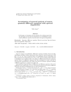
Figure 2.1 The objective function (Eq. (2.1)) is minimized when
µ coincides to the peak frequency of kY (ω)k2
function to obtain the frequency estimate. This concept will be applied also in the following
extended versions.
Let kY (ω)k2 be the observed short-time power spectrum of a single tone signal (complex
sinusoid). The shape of this distribution depends on the shape of the window function we
choose to use. Assuming the particular case where the peak and the mean frequencies of
this distribution coincide (where the distribution is symmetric about the peak), then one
can obtain the frequency estimate by finding µ that minimizes
Z ∞
°2
¡
¢2 °
ω − µ °Y (ω)° dω.
(2.1)
−∞
Consequently, the frequency estimate is derived as the mean of the distribution:
Z ∞
°
°2
ω °Y (ω)° dω
.
µ = Z−∞∞ °
°
°Y (ω)°2 dω
(2.2)
−∞
2.2.3
Single-Voice F0 Estimation and Overtone Separation
If one thinks of applying the above method to the single voice case, one may want to
separate overtones as if one is dealing with the single tone case problems separately. For this
Chapter 2 Harmonic Clustering
9
Figure 2.2 The objective function (Eq. (2.12)) can be monotonically decreased by
iteratively updating Cn and µ while keeping the other fixed.
purpose, we introduce a binary mask function defined by
1, ω ∈ Cn
,
1Cn (ω) =
0, ω ∈
/ Cn
(2.3)
where Cn is the set of the frequencies dominated by the nth overtone, which satisfies, for any
i and j such that i 6= j,
Ci
\
Cj = ∅.
(2.4)
If we decide not to discard any of the power spectrum portions, then
N
[
n=1
and thus for all ω ∈ R,
Cn = R(−∞, ∞),
N
X
(2.5)
1Cn (ω) = 1,
(2.6)
n=1
because it is proved by the formula:
1SI
(ω) =
i=1 Ci
I
X
i=1
1Ci (ω) −
X
i,j:i<j
1Ci T Cj (ω) +
X
i,j,k:i<j<k
1Ci T Cj T Ck (ω) − · · · .
(2.7)
Using such a masking function, one is able to describe a masked power spectrum portion by
°
°2
1Cn (ω)°Y (ω)° ,
(2.8)
10
Chapter 2 Harmonic Clustering
that correspond to the nth overtone. Therefore, we can apply the same method described in
Subsection 2.2.2 and
Z
∞
−∞
¡
°
°2
¢2
ω − µn 1Cn (ω)°Y (ω)° dω
(2.9)
corresponds to the cost function for the frequency estimate of the nth overtone. As we want
to make the cost function as small as possible not only for the nth overtone but for all the
components at the same time, we should write as follows the objective function in the single
voice case:
N Z
X
n=1
∞
−∞
¡
°
°2
¢2
ω − µn 1Cn (ω)°Y (ω)° dω.
(2.10)
If we further assume that the overtone frequencies are integer multiplies of the fundamental
frequency µ such that
µn = nµ,
(2.11)
then the objective function can be written further as
N Z ∞
X
°
°2
¡
¢2
ω − nµ 1Cn (ω)°Y (ω)° dω.
(2.12)
while keeping the other fixed. In each iteration, Cn and µ should be updated to
n
o
0
2
Cn = ω : n = argmin (ω − n µ) ,
(2.13)
n=1
−∞
This objective function can be monotonically decreased by iteratively updating Cn and µ
µ=
Z
N
X
n
n=1
N
X
n=1
n0
∞
−∞
n2
Z
°
°2
ω 1Cn (ω)°Y (ω)° dω
∞
−∞
°
°2
1Cn (ω)°Y (ω)° dω
.
(2.14)
The update of Cn separates the observed power spectrum kY (ω)k2 into clusters corresponding to the overtones using the F0 estimated hypothetically at the previous step and the
update of µ reestimates F0 using these spectral clusters.
2.2.4
Multipitch Estimation and Source Separation
The method derived above is easily extendable to the multisource case. Let the binary
mask function, used to extract the nth partial component of the k th source, be defined by
1, ω ∈ Ck,n
,
(2.15)
1Ck,n (ω) =
0, ω ∈
/ Ck,n
Chapter 2 Harmonic Clustering
11
where Ck,n is the set of the frequencies dominated by the nth overtone of the k th source. It
is assumed here again that
K X
N
X
1Ck,n (ω) = 1.
(2.16)
k=1 n=1
Using such a masking function, one is able to describe a masked power spectrum portion by
°
°2
1Ck,n (ω)°Y (ω)° ,
(2.17)
that correspond to the nth overtone of the k th source. Therefore, if we denote by µk the F0
estimate of the k th source, then
Z ∞
−∞
¡
°
°2
¢2
ω − nµk 1Ck,n (ω)°Y (ω)° dω
(2.18)
corresponds to the cost function for the frequency estimate of the nth overtone of the k th
source. As we want to make the cost function as small as possible not only for this component
but for all the components at the same time, we should write as follows the objective function:
N Z ∞
K X
X
°
°2
¡
¢2
ω − nµk 1Ck,n (ω)°Y (ω)° dω.
(2.19)
−∞
k=1 n=1
This objective function can be monotonically decreased in a similar way by iteratively updating Ck,n and µk while keeping the other fixed. In each iteration, Ck,n and µk should be
updated to
Ck,n =
µk =
n
o
ω : (k, n) = argmin (ω − n0 µk0 )2 ,
Z
N
X
n
n=1
N
X
n=1
∞
−∞
n2
(2.20)
k0 ,n0
Z
°
°2
ω 1Ck,n (ω)°Y (ω)° dω
∞
−∞
°
°2
1Ck,n (ω)°Y (ω)° dω
.
(2.21)
The update of Ck,n separates the observed power spectrum kY (ω)k2 into clusters each of
which corresponds to an overtone of one particular source using the F0 s estimated hypothetically at the previous step and the update of µk s reestimates F0 s using these spectral
clusters.
This iterative algorithm therefore consists of the source separation step and the multipitch
estimation step, leading us to solve a joint optimization problem of source separation and
multipitch estimation. We call this method “Harmonic Clustering”. We reformulate this
idea in Chapter 3 and try to explain it from the Bayesian point of view, which enables
various extensions.
Chapter 3
Bayesian Harmonic Clustering
3.1
Introduction
In this chapter, we aim at extending the idea introduced in Chapter 2. The Harmonic
Clustering is extended to a principle based on the estimation of the optimal fuzzy masking
function for the clustering source by source of the power spectrum of the mixed sound of
interest. Whether each of the spectral clusters has a harmonic structure or not is considered
to be the criterion for this optimization problem. More specifically, we will consider a decomposition of the power spectrum of the mixed sound in which every spectral clusters has
a harmonic structure as the optimal solution. We will show that this optimization problem
is equivalent to the problem of minimizing the distortion between the power spectrum of the
mixed sound and a mixture of spectral cluster models used as the clustering criterion. Meanwhile, from the viewpoint of statistical estimation, the distortion minimization procedure is
none other than the regression analysis. It follows from this that the method constitutes
in maximizing a likelihood function. Thus looking at the problem from the perspective of
statistical estimation, the empirical constraints which are necessary in any undetermined
problem can now be introduced, based on Bayes theorem, in the form of prior distributions.
Moreover, as many empirical constraints which at first looked irrelevant can now be expressed with the same measure (that is, probability), the problem becomes more organized,
and the perspective of a formulation and the intuitive meaning of the problem appear more
clearly. Furthermore, through model selection, estimation of the optimal number of clusters,
i.e. the number of sources, in the sense of posterior distribution is also performed.
As we explained in the preceding paragraph, this “extended” Harmonic Clustering can be
understood as the minimization of the distortion between the power spectrum of the mixed
12
Chapter 3 Bayesian Harmonic Clustering
13
sound and a mixture of spectral cluster models, or as the optimal decomposition (clustering)
of the power spectrum using spectral cluster models. Consequently, after deriving in the
following section the specific form of a spectral cluster model from the ideal case of periodic
signal models, we formulate in section Section 3.3 the problem separately from these two
points of view and show that they eventually both lead to the same algorithm. Then,
in sections Section 3.4 and Section 3.5, we show that optimal estimation under empirical
constraints can be performed through Maximal A Posteriori estimation, and that a criterion
for the source number estimation can be obtained from the model selection criterion.
3.2
3.2.1
Spectral Cluster Model
Definition of Fourier Transform Pair
Denoting by Y (ω) the Fourier transform of y(t), the Fourier transform pair is defined by
Z ∞
£
¤
1
F y(t) = Y (ω) = √
y(t)e−jωt dt
(3.1)
2π −∞
Z ∞
£
¤
1
−1
F
Y (ω) = y(t) = √
Y (ω)ejωt dω.
(3.2)
2π −∞
3.2.2
Definition of Analytic Signal
We define the analytic signal of a real signal x(t) by
y(t) = x(t) + jz(t),
where z(t) is the Hilbert transform of x(t), defined as
Z
1 ∞ x(τ )
z(t) =
dτ.
π −∞ t − τ
3.2.3
(3.3)
(3.4)
Gabor Transform Output of Periodic Signal Model
Assuming that all source signals are perfectly periodic in a short time range, we will
consider as the spectral cluster model the output of the Gabor transform (STFT) of a
periodic signal model around t = 0. Consider here as the k th source signal model the
analytic signal representation of a periodic signal given by
fk (t) ,
N
X
n=1
e
ak,n ej (nµk t+ϕk,n ) , t ∈ (−∞, ∞),
(3.5)
14
Chapter 3 Bayesian Harmonic Clustering
where µk is the fundamental frequency, ϕk,n the starting phase and e
ak,n the amplitude of the
nth partial, respectively. Denoting by w(t) a window function, let
gk (t) , w(t)fk (t)
(3.6)
be the short-time signal enhanced by w(t) around t = 0. As the window function w(t) ≥ 0
can be chosen arbitrary, we choose to use a Gaussian window. This type of STFT is called
the Gabor transform. The Fourier transform of the left- and right-hand sides of Eq. (3.6)
is, by the convolution theorem, given by
1
Gk (ω) = √ W (ω) ∗ Fk (ω)
2π
Ã
!
N
√ X
1
2π
e
ak,n ejϕk,n δ (ω − nµk )
= √ W (ω) ∗
2π
n=1
=
N
X
n=1
e
ak,n ejϕk,n W (ω − nµk ),
(3.7)
(3.8)
(3.9)
£
¤
£
¤
where Fk (ω) , F fk (t) and W (ω) , F w(t) . As w(t) is a Gaussian window, its Fourier
transform is again a Gaussian-type function such that
µ
ω2
W (ω) = exp − 2 .
4σ
(3.10)
Hence, Eq. (3.9) can be written as
Gk (ω) =
N
X
n=1
e
ak,n ejϕk,n exp
Ã
¡
ω − nµk
−
4σ 2
¢2 !
.
(3.11)
The power spectrum of Eq. (3.11) can be written as
° N
Ã
X
°
°2 °
°Gk (ω)° = °
e
ak,n ejϕk,n exp −
°
°
n=1
°
Ã
N
X°
°
ak,n ejϕk,n exp −
=
°e
°
¢2 !°
°2
°
°
°
¢2 !°
¡
°2
ω − nµk
°
°
2
°
4σ
n=1
à ¡
à ¡
¢2 !
¢2 !
0
X
0
ω
−
nµ
ω
−
n
µ
k
k
+
e
ak,ne
ak0 ,n0 ej (ϕk,n −ϕk0 ,n0 ) exp −
exp −
.
4σ 2
4σ 2
n6=n0
¡
ω − nµk
4σ 2
(3.12)
If we now assume that the time-frequency components are sparsely distributed so that the
partials rarely overlap, the second term could be negligibly smaller than the first term in
Chapter 3 Bayesian Harmonic Clustering
15
the above equation. This assumption justifies the additivity of power spectra and the power
spectrum of the k th source signal model is then expressed as a Gaussian mixture model:
à ¡
¢2 !
N
°
°2 X
ω
−
nµ
k
°Gk (ω)° ≈
,
(3.13)
e
ak,n 2 exp −
2
2σ
n=1
whose maxima are centered over prospective harmonics ω = nµk . Putting ak,n ,
√
2πσe
ak,n 2 ,
one finally obtains
N
X
°
°
a
°Gk (ω)°2 ≈
√ k,n exp
2πσ
n=1
3.2.4
Ã
¡
ω − nµk
−
2σ 2
¢2 !
.
(3.14)
Constant Q Filterbank Output of Periodic Signal Model
Similarly, one can derive as well the constant Q filterbank output of a periodic signal
model. Let the wavelet basis function defined by
µ
1
u−t
ψα,t (u) , √
ψ
,
α
2πα
(3.15)
where α is the scale parameter, t the shift parameter and ψ(u) an arbitrary analyzing wavelet
that has the center frequency of 1 and satisfies the admissible condition. ψα,t (u) is used to
measure the component of period α at time t. Now letting
fk (u) ,
N
X
n=1
e
ak,n ej (nµk u+ϕk,n ) , u ∈ (−∞, ∞)
(3.16)
be the k th source signal model, its continuous wavelet transform is defined by
E
¡
¢ D
Wk log α1 , t , fk (u), ψα,t (u)
u∈(−∞,∞)
D
E
= Fk (ω), Ψα,t (ω)
,
(3.17)
(3.18)
ω∈(−∞,∞)
where Fk (ω) , F [fk (u)] and Ψα,t (ω) , F [ψα,t (u)] The equality in the second line follows
from the Parseval’s theorem. Defining by Ψ(ω) , F [ψ(u)], then the Fourier transform of
Eq. (3.15) can be written as
Ψα,t (ω) = Ψ(αω)e−jωt ,
(3.19)
and from Eq. (3.18), one obtains
¡
Wk log
1
,t
α
¢
=
Z
∞
−∞
Fk (ω)Ψ∗ (αω)ejωt dω.
(3.20)
16
Chapter 3 Bayesian Harmonic Clustering
One immediately realizes that Eq. (3.20) amounts to the inverse Fourier transform of
Fk (ω)Ψ(αω). Wk (log α1 , t) could thus be interpreted as an output signal from the subband
filter with center frequency of 1/α and with frequency response Ψ(αω) with the input fk (t).
The Fourier transform of the k th source signal model is given as
Fk (ω) =
√
2π
N
X
n=1
¡
¢
e
ak,n ejϕk,n δ ω − nµk .
(3.21)
By substituting this result into Eq. (3.20), one obtains
¡
Wk log
1
,t
α
¢
=
N
X
n=1
e
ak,n ejϕk,n Ψ∗ (anµk )ejnµk t .
(3.22)
By changing the variable x = log α1 and by putting Ωk , log µk , Wk can be expressed in the
time-logfrequency domain:
Wk (x, t) =
N
X
n=1
³
´
Ωk
e
ak,n Ψ∗ ne−x+Ωk ej (ϕk,n +ne t) .
(3.23)
We will henceforth simply call Ωk the pitch frequency. As the frequency characteristic Ψ(ω)
of the analyzing wavelet can be chosen arbitrarily, we use here the following unimodal real
function whose maximum is taken at ω = 1 (see Fig. 3.1):
à ¡
¢2 !
log
ω
exp −
(ω > 0)
4σ 2
.
Ψ(ω) =
0
(ω 5 0)
(3.24)
Eq. (3.23) is then given as
Wk (x, t) =
N
X
n=1
Ã
e
ak,n exp
¢2 !
x − Ωk − log n
Ωk
−
ej (ϕk,n +ne t) ,
2
4σ
¡
(3.25)
and the resulting power spectrum of Eq. (3.22) can be written as
° N
°2
à ¡
¢2 !
°
X
°
°2 °
x
−
Ω
−
log
n
Ω
k
j (ϕk,n +ne k t) °
°Wk (x, t)° = °
e
ak,n exp −
e
°
°
2
°
°
4σ
n=1
°
°2
à ¡
¢2 !
N °
°
X
x
−
Ω
−
log
n
k
°
j (ϕk,n +neΩk t) °
ak,n exp −
=
e
°e
°
°
°
4σ 2
n=1
à ¡
¢2 !
X
x − Ωk − log n
+
e
ak,ne
ak0 ,n0 exp −
4σ 2
n6=n0
à ¡
¢2 !
x − Ωk0 − log n0
Ωk
0 Ωk 0
exp −
ej (ne t+n e t+ϕk,n +ϕk0 ,n0 ) . (3.26)
2
4σ
Chapter 3 Bayesian Harmonic Clustering
17
Ψ(ω)
1
0.5
0
0
1
2
4
6
ω
8
10
Figure 3.1 Frequency response Ψ(ω) given by Eq. (3.24) for σ = 21 .
If we assume here again that the time-frequency components are sparsely distributed so
that the partials rarely overlap, the second term could be negligibly smaller than the first
√
ak,n k2 for simplicity of notation, one
term in the above equation. Putting ak,n , 2πσke
obtains a Gaussian mixture model whose maxima are centered over prospective harmonics
x = Ωk (t) + log n:
N
K X
X
°
°
a
°W (x, t)°2 ≈
√ k,n exp
2πσ
k=1 n=1
Ã
¢2 !
x − Ωk − log n
−
,
2σ 2
¡
(3.27)
whose graphical representation can be seen in Fig. 4.1. Let us denote simply by kW (x)k2
the power spectrum kW (x, 0)k2 and consider it as the spectral cluster model. We are now
able to assess how clearly a harmonic structure appears in a spectral cluster by measuring
the distance between the cluster and this cluster model.
3.3
3.3.1
Principle
Optimal Separation of Power Spectrum
We will henceforth suppose the situation where we obtain the observed spectrum by constant Q analysis. We formulate the problem of the decomposition of the observed power
18
Chapter 3 Bayesian Harmonic Clustering
Figure 3.2 Graphical representation of Eq. (3.27).
spectrum into distinct clusters, which is said to be ‘optimal’ when all the clusters are harK
monically structured. Let Θ refers to {Ωk ,{ak,n }N
n=1 }k=1 .
We define by kY (x)k2 the power spectrum of the signal of interest obtained by the constant
Q analysis. Let us introduce a spectral masking function mk (x) that extracts the components
associated with the k th source from kY (x)k2 . For x ∈ R, mk (x) indicates the percentage of
the portion of kY (x)k2 shared to the k th source, such that satisfies
K
X
mk (x) = 1
(3.28)
k=1
0 < mk (x) < 1, k ∈ {1, · · · , K}.
(3.29)
Assuming again additivity of power spectra, a portion of the observed power spectrum is
thus given arbitrarily by
°
°2
mk (x)°Y (x)° , x ∈ (−∞, ∞),
(3.30)
which we call a “spectral cluster”. As we expect the spectral cluster to be associated with a
single harmonic structure, we need to introduce a measure function that specifies how clearly
a harmonic structure appears in this spectral cluster. One possible measure function may
be the I divergence [30] (The reason of this choice will be made clear in Subsection 3.3.2.)
between mk (x)kY (x)k2 and the spectral cluster model kWk (x)k2 we derived in Subsection
3.2.4:
Z
∞
−∞
!
°
°2 ³
´
°
°
°
°2
°
°
m
(x)
Y
(x)
k
2
mk (x)°Y (x)° log
− mk (x)°Y (x)° − kWk (x)k2
dx.
2
kWk (x)k
Ã
(3.31)
The more clearly the harmonic structure appears in mk (x)kY (x)k2 , the smaller this value
may be. The optimal clustering achieved by minimizing their sum with respect to mk (x)
Chapter 3 Bayesian Harmonic Clustering
and Θ:
K Z
X
k=1
∞
−∞
Ã
19
!
°
°2 ³
´
°
°
°
°2
°
°
m
(x)
Y
(x)
k
2
mk (x)°Y (x)° log
− mk (x)°Y (x)° − kWk (x)k2
dx, (3.32)
2
kWk (x)k
tries to make all separate clusters to be harmonically structured.
In the same way, let us introduce a spectral masking function mk,n (x) that extracts the
components associated with the nth partial of the k th source from kY (x)k2 . For x ∈ R,
mk,n (x) indicates the percentage of the portion of kY (x)k2 shared to the nth partial of the
k th source, such that satisfies
K X
N
X
mk,n (x) = 1
(3.33)
k=1 n=1
0 < mk,n (x) < 1, k ∈ {1, · · · , K}, n ∈ {1, · · · , N }
(3.34)
a portion of the observed power spectrum is thus given arbitrarily by
°
°2
mk,n (x)°Y (x)° , x ∈ (−∞, ∞)
(3.35)
which we call a “spectral cluster”. In the same way, the optimal clustering can be achieved
by minimizing
Φ(Θ, m) =
N Z
K X
X
k=1 n=1
∞
−∞
Ã
°
°2
°
°
°
°2
m
k,n (x) Y (x)
mk,n (x)°Y (x)° log
Wk,n (x)
!
´
°
°2
− mk,n (x)°Y (x)° − Wk,n (x) dx. (3.36)
³
with respect to Θ and mk,n (x). To do so, we shall find it most convenient to minimize this
objective function recursively with respect to mk,n (x) and Θ while keeping the other fixed.
As both steps necessarily decreases the objective function, which is bounded by below, the
convergence of this recursive algorithm is thus guaranteed.
We shall first derive the update equation for the spectral masking function mk,n (x) that
minimizes Φ(Θ, m) with fixed Θ. Adding to the objective function the Lagrange multiplier
term that ensures Eq. (3.33):
−
Z
∞
−∞
λ(x)
Ã
K X
N
X
k=1 n=1
mk,n (x) − 1
!
dx,
its partial derivative with respect to mk,n (x) is given as
µ
°2
Wk,n (x)
∂Φ(Θ, m) °
°
°
= Y (x)
log
− 1 − λ(x).
∂m
mk,n (x)
(3.37)
(3.38)
20
Chapter 3 Bayesian Harmonic Clustering
Setting this to 0, one obtains
ð
!
°
°Y (x)°2
mk,n (x) = Wk,n (x) exp
−1 .
λ(x)
From Eq. (3.33), the Lagrange multiplier λ(x) is given as
ð
!
°
K X
N
°Y (x)°2
X
Wk,n (x) exp
− 1 = 1,
λ(x)
k=1 n=1
(3.39)
(3.40)
which yields
Wk,n (x)
m
b k,n (x) = X X
.
Wk,n (x)
k
(3.41)
n
Substituting this result into Eq. (4.31), we obtain
Ã
!
°
°
Z ∞
°Y (x)°2
XX
°
°
°
°2
°Y (x)°2 −
dx,
°
°
X
X
Φ(Θ, m)
b =
−
W
(x)
Y
(x)
log
k,n
−∞
Wk,n (x)
n
k
k
n
(3.42)
from which we see that what we are trying to minimize w.r.t Θ is the I divergence between
the whole observed power spectrum and the sum of all the spectral cluster models.
3.3.2
Minimization of Distortion Measure
Optimally fitting a parametric function with respect to observed values corresponds, from
the viewpoint of statistical estimation, to regression analysis. That is, if we consider that
the observations kY (xi )k2 at the discrete points xi are generated from the regression model
kW (x)k2 with a randomly oscillating noise, one can come back naturally to a maximum
likelihood estimation problem. Denoting by
¯ ¢
¡
P kY (xi )k2 ¯Θ
(3.43)
the output probability of observation kY (xi )k2 from the regression model kW (x)k2 with
parameter Θ (in other words, the likelihood of the parameter Θ of the regression model
with respect to the observation kY (xi )k2 ), our goal is to maximize the joint probability that
all the observations Y = (kY (x1 )k2 , · · · , kY (xI )k2 )T were generated independently by the
regression model,
I
Y
¯ ¢
¡
P (Y |Θ) =
P kY (xi )k2 ¯Θ ,
i=1
(3.44)
Chapter 3 Bayesian Harmonic Clustering
21
or its logarithm (hereafter mentioned as log-likelihood)
log P (Y |Θ) =
I
X
i=1
For example, if we now consider the relation
¯ ¢
¡
log P kY (xi )k2 ¯Θ .
°
°
°
°
°Y (xi )°2 = °W (xi )°2 + ²i ,
(3.45)
(3.46)
it is often assumed that ²i is a Gaussian white noise, i.e. ²i ∼ N (0, ν 2 ), and in this case
expression (3.43) is defined as
³°
°2 °
°2 ´2
°
°
°
Y (xi ) − W (xi )°
¯ ¢
¡
1
2¯
exp −
P kY (xi )k Θ = √
.
2ν 2
2πν
Substituting it into (3.45), the quantity to maximize becomes
³°
°2 °
°2 ´2
°
°
°
I
Y (xi ) − W (xi )°
X
1
−
log √
,
2ν 2
2πν
i=1
(3.47)
(3.48)
and we thus see that this is equivalent to the least mean square estimation problem between kY (x)k2 and kW (x)k2 . However, despite the fact that kY (x)k2 is a power spectrum
distribution density, the above likelihood function P (kY (xi )k2 |Θ) is non-zero even when
¯ ¢
¡
kW (xi )k2 < 0. Of course, P kY (xi )k2 ¯Θ does not need to be a Gaussian distribution, and
for other distribution shapes the essential interpretation as a regression analysis problem is
not lost. Here, it is desirable that P (kY (xi )k2 |Θ) is only defined for kW (xi )k2 = 0, and
the Poisson distribution is a representative example of such a probability density function.
Poisson distribution is usually defined as a probability density function of random variables
on non-negative integers, but it can be extended to a probability density function of random
variables on all non-negative real numbers. Distinguishing it from the usual Poisson distribution, we will call it continuous Poisson distribution. The continuous Poisson distribution
of kY (xi )k2 with parameter kW (x)k2 is given by
°
°
°
°2 ³°
´°Y (xi )°2
°
°
°
2
− W (xi )
°W (xi )°
¯ ¢ e
¡
2¯
³°
´
P kY (xi )k Θ =
,
°2
Γ °Y (xi )° + 1
(3.49)
where Γ(·) is the Gamma function
Γ(z) ,
Z
0
∞
e−t tz−1 dt,
(3.50)
22
Chapter 3 Bayesian Harmonic Clustering
and the likelihood is defined as 0 when kW (x)k2 is negative. The shape of the distribution
of the likelihood of Θ with respect to kW (xi )k2 is shown in Fig. 3.3.2. Substituting this
expression into (3.45), we obtain the log-likelihood to maximize:
L(Θ) ,
=
I
X
¯ ¢
¡
log P kY (xi )k2 ¯Θ
i=1
I µ
X
i=1
´
³°
°
°
°
°
°
°
°
°Y (xi )°2 log °W (xi )°2 − °W (xi )°2 − log Γ °Y (xi )°2 + 1 .
(3.51)
(3.52)
As shown in Fig. 3.3.2, the above distribution is a unimodal distribution reaching its maximum only when kY (x)k2 = kW (x)k2 , which implies as expected that this maximum likelihood problem amounts to a model fitting one. In the same way as we have shown that
when the likelihood function is considered to be a Gaussian distribution the maximum likelihood problem becomes equivalent to a least-mean square estimation, the maximum likelihood problem under the above continuous Poisson distribution type likelihood function is
°
°2
equivalent to the minimization with respect to °W (x)° of a distortion measure between
distributions called I-divergence:
Ã
!
°
°
I
³°
°Y (xi )°2
X
°
°2
°2 °
°2 ´
°Y (xi )° log °
.
° − °Y (xi )° − °W (xi )°
°W (xi )°2
i=1
(3.53)
This is clear if we compare this expression to Eq. (3.52). As shown in Fig. 3.3.2, the
distortion measure inside the parentheses in Eq. (3.53) is a non-symmetrical measure giving
more penalty to positive errors, and thus emphasizes the goodness of fitting between spectral
peaks. In that regard, it is similar to the Itakura-Saito distance [54] derived in Linear
Predictive Coding (LPC).
We have explained the model fitting from a statistical estimation point of view. From
the above perspective, we can redefine the problem as a Maximum A Posteriori estimation
problem by introducing very naturally a prior distribution P (Θ), which we will explain in
more details later. In the next subsection, we show how one can derive an efficient iterative
estimation algorithm.
3.3.3
Iterative Maximum Likelihood Estimation
Goto [45], by considering hypothetically the frequencies as observation data and the normalized power spectrum as the probability distribution of the observation data, uses the EM
Chapter 3 Bayesian Harmonic Clustering
23
0.18
0.16
likelihood of Θ
0.14
0.12
0.1
0.08
0.06
0.04
0.02
0
0
5
10
2
15
20
|| W(x) ||
Figure 3.3 Graphical representation of the likelihood function (3.49) for kY (x)k2 = 5.
algorithm to maximize the probability that the whole observation data have been generated
by a statistical model represented by a GMM. However, from a statistical signal processing
viewpoint, it is not obvious whether the assumption that the frequencies behave stochastically is appropriate or not. As the power spectrum kY (x)k2 is actually not a probability
distribution and the mixed sound model kW (x)k2 is also not a statistical model, formulas
from the probability theory (Bayes theorem, marginalization operations, etc.) cannot be
applied in a rigorous manner to their distributions, and the fact that the EM algorithm
derived using Bayes’ rule could be used to perform approximation between them is thus definitely non-trivial. The goal of this subsection is to derive an iterative estimation algorithm
formally equivalent to the EM algorithm without making use of Bayes’ rule. This derivation
justifies of course our method, but eventually also supports simultaneously the validity of
Goto’s method.
The goal of the problem (maximum likelihood estimation) is now
b = argmax L(Θ).
Θ
Θ
(3.54)
°
Looking back at Eq. (3.14), °W (x)k2 can be written as a sum over k and n of terms of the
form
ak,n
Wk,n (x) , √
exp
2πσ
Ã
¡
x − Ωk − log n
−
σ2
¢2 !
,
24
Chapter 3 Bayesian Harmonic Clustering
Figure 3.4 The distortion measure inside the parentheses in (3.53) for kW (x)k2 = 5.
and one can thus write L(Θ) as
!
Ã
N
N
K X
K X
I
³°
´
X
X
X
°2
°
°2
°Y (xi )° log
Wk,n (xi ) − log Γ °Y (xi )° + 1
Wk,n (xi ) −
.
L(Θ) =
k=1 n=1
k=1 n=1
i=1
(3.55)
Approximating the second term in the parentheses above by a Gaussian integral, we get
I
X
i=1
and thus
P P
i
k,n
Wk,n (xi ) ≈
Wk,n (xi ) ≈
P
k,n
Z
∞
−∞
Wk,n (x)dx = ak,n ,
(3.56)
ak,n . However, one cannot obtain analytically Θ max-
imizing the above L(Θ). The specific reason for this is that L(Θ) has a nonlinear term
expressed as the logarithm of a sum of several exponential terms.
If we now notice that the logarithm function is convex, introducing arbitrary weight functions mk,n (x) such that ∀x,
K X
N
X
k=1 n=1
mk,n (x) = 1,
∀k, n : 0 < mk,n (x) < 1,
(3.57)
Chapter 3 Bayesian Harmonic Clustering
25
we obtain the following inequality:
Ã
!
N
I
K X
K X
N
³°
´
X
X
X
°
°2
°2
W
(x
)
k,n
i
°
°
°
°
L(Θ) =
− log Γ Y (xi ) + 1
−
ak,n
Y (xi ) log
mk,n (xi )
mk,n (xi )
i=1
k=1 n=1
k=1 n=1
ÃK N
!
I
K X
N
³°
´
X
XX°
X
°2
°2
W
(x)
k,n
°
°
°
°
=
Y (xi ) mk,n (xi ) log
− log Γ Y (xi ) + 1
−
ak,n .
mk,n (xi )
i=1
k=1 n=1
k=1 n=1
(3.58)
Let us denote the right-hand side of this inequality by L− [Θ, m]:
L− [Θ, m]
!
à K N
K X
N
I
³°
´
X
XX°
X
°2
°2
W
(x
)
k,n
i
°
°
°
°
−
ak,n .
,
Y (xi ) mk,n (xi ) log
− log Γ Y (xi ) + 1
mk,n (xi )
i=1
k=1 n=1
k=1 n=1
(3.59)
What must be noticed in the above inequality is not only that a lower bound function (righthand side) has been obtained for L(Θ), but that in this lower bound function L− (Θ, m) the
exponential inside Wk,n (x) has disappeared and become a second-order function in Ωk , thus
suggesting that it should be possible to obtain analytically Ωk maximizing L− (Θ, m). Using
this fact, we develop hereafter a method to increase L(Θ) indirectly using L− (Θ, m).
L− (Θ, m) contains a new variable mk,n (x) which did not appear in L(Θ). For any fixed
Θ, if we maximize the lower bound function with respect to mk,n (x), equality is reached
in the inequality, with L− (Θ, m) always staying smaller than L(Θ). The latter is a direct
consequence of the inequality while the former can be verified by looking for mk,n (x) maximizing L− (Θ, m). Let us first differentiate with respect to mk,n (xi ) the lower bound function
to which the Lagrange multiplier term
à K N
!
I
X
XX
−
λi
mk,n (xi ) − 1
i=1
(3.60)
k=1 n=1
has been added. We obtain
µ
°2
Wk,n (xi )
∂L− °
°
°
= Y (xi )
log
− 1 − λi ,
∂m
mk,n (xi )
(3.61)
and putting this to 0, we get
ð
!
°
°Y (xi )°2
mk,n (xi ) = Wk,n (xi ) exp
−1 .
λi
(3.62)
26
Chapter 3 Bayesian Harmonic Clustering
According to condition (3.57),
ð
!
°
°Y (xi )°2
Wk,n (xi ) exp
− 1 = 1,
λi
k=1 n=1
K X
N
X
(3.63)
and the Lagrange multipliers λi can thus be obtained. We eventually get
Wk,n (xi )
mk,n (xi ) = X X
.
Wk,n (xi )
k
(3.64)
n
Introducing this result into Eq. (3.59), we can verify that indeed L− (Θ, m) = L(Θ).
From this state of equality, if we now increase L− (Θ, m) with respect to Θ, automatically
L(Θ) shall also increase. This is due to the fact that the convex inequality ensures that
L(Θ) is necessarily larger than the increased L− (Θ, m). From the above, we can see that
performing alternately the maximization of L− (Θ, m) with respect to mk,n (x) and an increase
of L− (Θ, m) with respect to Θ, L(Θ) will monotonically increase. The parameter estimation
algorithm is thus composed of the two following steps:
Step 0 Set the initial parameters Θ0 , put ` = 1.
Step 1 m(`) = argmax L− (Θ(`−1) , m).
m
(`)
Step 2 Set Θ
as Θ such that L− (Θ, m(`) ) = L− (Θ(`−1) , m(`) ), put ` ← ` + 1
and go back to Step 1.
As L(Θ) is bounded above, from the preceding discussion, we can see that the convergence
of the iterative estimation algorithm is guaranteed.
A point which should particularly be noticed here is that the iterative estimation of the
pitch frequencies Ωk through the EM algorithm, which could not be obtained in the methods
of Chazan et al. [22] and Jinachitra et al. [57], can now be performed. We shall give the
details about the update equations of the model parameter set Θ later, but let us verify here
first that the update equation for Ωk can be obtained analytically. Putting to 0 the partial
derivative of L− (Θ, m) with respect to Ωk
I
N
°
∂L− X X °
°Y (xi )°2 mk,n (xi ) xi − Ωk − log n
=
∂Ωk
σ2
i=1 n=1
(3.65)
the update equation for Ωk
bk =
Ω
I X
N
X
°
°
¡
¢
°Y (xi )°2 mk,n (xi ) xi − log n
i=1 n=1
I X
N
X
i=1 n=1
°
°
°X(xi )°2 mk,n (xi )
(3.66)
Chapter 3 Bayesian Harmonic Clustering
27
can be obtained analytically.
The iterative computation presented above eventually follows formally the same procedure
as the EM algorithm, but as we do not assume that kY (x)k2 and kW (x)k2 are probability
distributions, its derivation method is slightly different from the original EM algorithm [33].
In that sense, the above derivation gives another interpretation of the EM algorithm.
3.4
3.4.1
Bayesian Harmonic Clustering
Maximum A Posteriori (MAP) Estimation
Based on the above preparatory work, from the viewpoint of statistical estimation as in
Subsection 3.3.2, the empirical constraints which are necessary in underdetermined problems
can be smoothly introduced through Bayes theorem, and many problems can be dealt with.
Moreover, as many empirical constraints which at first looked irrelevant can now be expressed
with the same measure (i.e., probability), the problem becomes more organized, and the
perspective of a formulation and the intuitive meaning of the problem appear more clearly.
First, from the Bayes theorem, the posterior probability of Θ is given by
P (Θ|Y ) =
P (Y |Θ)P (Θ)
.
P (Y )
(3.67)
It is then through the prior probability P (Θ) that the relation to the empirical constraints
appears. Let us consider here the maximization of the posterior probability P (Θ|Y ):
argmax P (Θ|Y ) = argmax P (Y |Θ)P (Θ)
Θ
Θ
³
´
= argmax log P (Y |Θ) + log P (Θ)
Θ
³
´
= argmax L(Θ) + log P (Θ) .
Θ
(3.68)
(3.69)
(3.70)
This is the Maximum A Posteriori estimation of the model parameters Θ. As can be seen
in Eq. (3.70), the objective function in this case is only the objective function L(Θ) used
in the discussion of Subsection 3.3.3, to which log P (Θ) has been added. As log P (Θ) does
not depend on mk,n (xi ), the update equation of mk,n (xi ) stays the same as (3.64). If we
can obtain update equations for Θ from L− (Θ, m) + log P (Θ), then in the same was as in
Subsection 3.3.3, we will be able to derive an iterative algorithm monotonically increasing
L(Θ) + log P (Θ).
28
Chapter 3 Bayesian Harmonic Clustering
3.4.2
Smoothness of Spectral Envelope
In speech and music, the empirical constraint that “the spectral envelope is smooth” is
relatively largely accepted. The necessary condition such that the spectral envelope is smooth
is that the values of ak,n and ak,n−1 should be sufficiently close. Therefore, one strategy is
to define the prior distribution such that the probability should get larger as the values of
ak,n and ak,n−1 become closer.
For simplicity, let us first suppose that in Θ, {Ωk } and {ak,n } are independent, and
furthermore that the {ak,n } are independent across sources. One can then separate the
variables as follows:
P (Θ) = P (Ω1 , · · · , ΩK )
Y
k
P (ak,1 , · · · , ak,N ).
(3.71)
We can decompose furthermore P (ak,1 , · · · , ak,N ) in
P (ak,1 , · · · , ak,N ) = P (ak,1 )P (ak,2 , · · · , ak,N |ak,1 )
= P (ak,1 )P (ak,2 |ak,1 )P (ak,3 , · · · , ak,N |ak,1 , ak,2 )
= ···
= P (ak,1 )P (ak,2 |ak,1 )P (ak,3 |ak,1 , ak,2 ) · · · P (ak,N |ak,1 , · · · , ak,N ).
(3.72)
If we now suppose that the power ak,n of the n-th harmonic component only depends on
the power ak,n−1 of the neighboring component, P (ak,1 , ak,2 · · · , ak,N ) can be expressed as a
Markov chain probability:
P (ak,1 , · · · , ak,N ) ≈ P (ak,1 )
N
Y
n=2
P (ak,n |ak,n−1 ).
(3.73)
The probability P (ak,n |ak,n−1 ) should become larger as the powers of the neighboring harmonic components are closer. Moreover, as ak,n is a power (and thus non-negative), we
would like to consider a probability distribution for which the probability density function
is only defined for ak,n = 0. For example, let us assume it follows the Gamma distribution:
−
(γ−1)ak,n
(γ − 1)γ ak,n γ−1 e ak,n−1
.
P (ak,n |ak,n−1 ) =
Γ(γ)
ak,n−1 γ
(3.74)
This distribution’s probability density function is only defined for ak,n = 0, and is a unimodal distribution which takes its maximum at the parameter ak,n−1 . γ > 0 is called shape
parameter, and as the peak of the distribution becomes sharper as γ becomes larger, it can
Chapter 3 Bayesian Harmonic Clustering
29
Figure 3.5 Illustration of P (ak,n |ak,n−1 ) when ak,n−1 = 5 (shape parameter γ = 3, 6, 12).
be considered as a constant, that is used for adjusting the effect of the prior distribution.
An illustration of the Gamma distribution is shown in Fig. 3.4.2.
If we assume P (Ω1 , · · · , ΩK ) and P (ak,1 ) follow uniform distributions (all values can be
taken evenly), from the above we obtain that log P (Θ) can be written specifically as
(γ − 1)γ
log P (Θ) = η + K(N − 1) log
Γ(γ)
à N
!
−1
X X (γ − 1)ak,n N
X
−
+
log ak,n + γ log ak,1 − (γ − 1) log ak,N , (3.75)
a
k,n−1
n=2
n=2
k
P
where η = log P (Ω1 , · · · , ΩK ) + k log P (ak,1 ) = const.
3.4.3
Update Equations for the Model Parameters
We can now finally derive the update equations of the Step 2 of Subsection 3.3.3. As
explained earlier, we want to obtain Θ increasing or maximizing L− (θ, m) + log P (Θ).
As log P (Θ) does not depend on Ωk , the update equation of µk is already given as presented
in (3.66). The update equation of the ak,n is performed, for each k, by using sequentially
from n = 1 to n = N the following update equations (Coordinate Descent method), ensuring
that L− (θ, m) + log P (Θ) does not decrease. Hereafter, let us write
Φk,n
I
X
°
°X(xi )k2 mk,n (xi ).
=
i=1
(3.76)
30
Chapter 3 Bayesian Harmonic Clustering
The update equation for ak,n can then be obtained as follows. We first put to 0 the partial
derivative of L− (θ, m) + log P (Θ) with respect to ak,1 ,
1
(γ − 1)ak,2
γ
Φk,1 − 1 +
−
,
2
ak,1
ak,1
ak,1
and obtain
b
ak,1
Φk,1 − γ
=
+
2
µ
(Φk,1 − γ)2
+ (γ − 1)ak,2
4
¶ 12
,
(3.77)
where ak,2 in the above update equation is the value updated one step before. Then putting
to 0 the partial derivative of L− (θ, m) + log P (Θ) with respect to ak,n (n = 2, · · · , N − 1),
1
ak,n
Φk,n − 1 −
γ−1
(γ − 1)ak,n+1
1
+
−
,
2
ak,n−1
ak,n
ak,n
we obtain
b
ak,n
Ã
µ
¶1 !
(Φk,n − 1)2 (γ − 1)(ak,n−1 + γ − 1)ak,n+1 2
ak,n−1
Φk,n − 1
=
+
+
, (3.78)
ak,n−1 + γ − 1
2
4
ak,n−1
where ak,n−1 is the latest updated value and ak,n+1 is the value updated one step before.
Finally, putting to 0 the partial derivative with respect to ak,N ,
∂L−
1
γ−1
γ−1
=
Φk,N − 1 −
+
,
∂ak,N
ak,N
ak,N −1
ak,N
we obtain
b
ak,N
¡
¢
ak,N −1 Φk,N + γ − 1
=
,
ak,N −1 + γ − 1
(3.79)
where ak,N −1 is the latest updated value.
3.5
3.5.1
A Criterion for Source Number Estimation
Model Selection using Bayesian Information Criterion
Another important characteristic of Bayesian statistical inference is that a model structure
selection criterion can be derived. Model structure specifies the model function class and the
number of free parameters, but as here the function class is fixed, it indicates the number of
free parameters. Model selection criterion is a criterion to determine comparatively which
kind of model structure shall have a model which would be likely to generate a given observation data. Up to now, the discussion was done under the assumption that the number
of sources K and the number of harmonic components N of the mixed sound model were
Chapter 3 Bayesian Harmonic Clustering
31
already known, but in general the number of sources mixed in the input mixed sound signal
is unknown. Therefore, if one could derive a model selection criterion, it would lead a new
criterion to estimate the number of sources K and the number of harmonic components N .
Meanwhile, as compared to the estimation of the number of sources K, estimating the
number of harmonic components is not engineeringly such an important problem, hereafter
for the sake of simplicity we shall assume that N is an experimentally fixed constant. Then,
e
through comparison of all the mixed sound models for K varying from K = 1 to K = K,
e is the maximum source number, and selection of the best model structure, the
where K
number of sources can be estimated.
We first express the model structure index as M (K) , where the superscript refers to the
number of sources, which is related to the number of free parameters. Similarly, denoting by
Θ(K) the number of model parameters of a mixed sound model for which the number sources
is K, the problem considered here is to find the model structure M (K) that maximizes the
posterior probability of M (K) ,
¡
P M
(K)
¡
¢ ¡
¢
P Y |M (K) P M (K)
¡ ¢
,
|Y =
P Y
¢
(3.80)
where Y refers to the set of observations kY (x1 )k2 , · · · , kY (xI )k2 . Assuming that the prior
probability P (M (K) ) of the model structure is a uniform distribution, the problem amounts
to performing the maximum likelihood estimation of the model structure:
¡
¢
c(K) = argmax P Y |M (K) .
M
(3.81)
M (K)
In Subsection 3.3.2, as we assumed implicitly that K was fixed, the model structure index
was actually omitted in the right-hand side of Eq. (3.44). If we now consider that K is an
unknown variable, P (Y |Θ) should be written more exactly P (Y |Θ(K) , M (K) ). Then, as
¢
¢ ¡
¢
¡
¡
P Y , Θ(K) |M (K) = P Y |Θ(K) , M (K) P Θ(K) |M (K) ,
if we marginalize both sides with respect to Θ(K) , from
Z
¢
¢ ¡
¢
¡
¡
(K)
= P Y |Θ(K) , M (K) P Θ(K) |M (K) dΘ(K)
P Y |M
Z
©
ª ¡
¢
= exp L(Θ(K) ) P Θ(K) |M (K) dΘ(K) ,
(3.82)
(3.83)
(3.84)
where, L(Θ(K) ) = log P (Y |Θ(K) , M (K) ), we can obtain the desired model selection criterion.
This is actually none other than the denominator of the right-hand side of Eq. (3.67). The
32
Chapter 3 Bayesian Harmonic Clustering
criterion for estimation of the model structure is thus the “marginal probability of the observation data”, which tends to be disregarded in the context of maximum likelihood estimation
and Maximum A Posteriori estimation of model parameters.
The next point that we have to discuss is how to obtain the marginal distribution of the
above equation. One could think of computing numerically the integral with respect to Θ(K) ,
but this would require considerable computational cost and is thus not realistic. Here we
can use the well-known Bayesian Information Criterion (BIC)[7, 93], model evaluation criterion derived by approximating the marginal probability of the above equation. Its principle
is based on the assumption that when the data number I (here referring to the number of
discrete frequency points) is sufficiently large, as the integrand in the above equation concentrates in the vicinity of the value of the maximal likelihood estimator (or of the Maximum A
b the integration value depends on the behavior in the neighborhood
Posteriori estimator) Θ,
b and L(Θ(K) ) and log P (Θ(K) |M (K) ) can be approximated around Θ
b (K) respectively
of Θ,
by their 2nd order and 0th order Taylor expansion [93]. This corresponds to approximating
the posterior distribution of Θ by a multidimensional Gaussian distribution centered on the
b of the maximum likelihood estimator (or of the Maximum A Posteriori estimator),
value Θ
and in case the maximum likelihood estimator is asymptotically normal, this approximation
is justified. The marginalization operation of (3.84) can then be easily performed. The above
question can thus be approximated in the following way:
n ¡
¡
¢
¢o ¡ (K) (K) ¢¡ ¢D(K) /2 −D(K) /2 ¯¯ ¡ (K) ¢¯¯−1/2
b (K) P Θ
b |M
b
P Y |M (K) ≈ exp L Θ
2π
I
,
¯J Θ
¯
(3.85)
where I is the number of elements of the observation time series Y , D(K) is the number of
free parameters in the mixed sound model kY(x)k2 when the number of sources is K, and
b (K) ) is the Fisher information matrix. Taking the logarithm of this equation, multiplying
J(Θ
by −2 and approximating further, we obtain the BIC:
¡
¢
− 2 log P Y |M (K)
¯ ¡ (K) ¢¯
¡ (K) ¢
¡ ¢
¡ (K) (K) ¢
b
b
b |M
¯ − D(K) log 2π − 2 log P Θ
≈ −2L Θ
+ D(K) log I + log ¯J Θ
¡ (K) ¢
b
+ D(K) log I.
(3.86)
≈ −2L Θ
For more details on the above derivation, we shall refer to [7, 93].
Chapter 3 Bayesian Harmonic Clustering
3.5.2
33
Model Selection Algorithm
In this subsection, we present the global structure of the Bayesian Harmonic Clustering
algorithm, including the Maximum A Posteriori estimation of the parameters and the model
selection of the spectral cluster models.
e of the number of sources K.
1. Set the initial value K
b (K) using the iterative algorithm
2. Estimate the Maximum A Posteriori parameter Θ
presented in Subsection 3.3.3.
e of the spectral cluster models. Detect the top K
e
(a) Set the initial parameters Θ K
peaks of the power spectrum kY (x)k2 and use them as initial parameters Ωk .
(b) Update mk,n (x) through Eq. (3.64).
(c) Update Ωk through Eq. (3.66).
(d) After updating ak,n through Eq. (3.77), Eq. (3.78) and Eq. (3.79), return to (b).
After convergence, proceed to 3.
3. Compute BIC(K) through Eq. (3.86). If K 6= 1, proceed to 4. If K = 1, proceed to 5.
4. Find the spectral cluster model with smallest power,
ǩ = argmin
k
N
X
ak,n ,
(3.87)
n=1
and eliminate it. Set K = K − 1 and return to 2.
5. Find K minimizing BIC. For this model structure, look for the Maximum A Posteriori
estimation Parameter
b
b (K)
b = argmin BIC(K) ⇒ Θ
K
(3.88)
K
as the final solution.
3.6
3.6.1
Experimental Evaluation
Condition
Considering music is the typical example of multipitch audio signal, the proposed method
was tested on a framewise musical note estimation task using 8 pieces of real music performance data excerpted from RWC music database (the list of the experimental data is shown
34
Chapter 3 Bayesian Harmonic Clustering
Table 3.1 Experimental conditions
frequency analysis
proposed algorithm
PreFEst-core[45]
Sampling rate
16 kHz
frame shift
32 msec
mother wavelet
Gabor function
frequency resolution
12.0 cent
frequency range
60–3000 Hz
initial # of harmonic kernels
10
# of partials
8
σ
3.0 × 10⁻³
r̄n
0.6547 × n−2
d¯
3.0
ρn
0.01 ×
pitch resolution
20 cent
# of partials
8
# of harmonic models
200
standard deviation of Gaussian
3.0
r̄n
0.6547 × n−2
d¯
3.0
1
n
in table 3.2). Time series of power spectrum was analyzed using Gabor wavelet transform
with frame shift of 16ms for input digital signals of 16kHz sampling rate. The lower bound
of the frequency range and the frequency resolution were 60Hz and 12cent, respectively. The
experimental conditions are shown in detail in table 3.1.
The purpose of this experiment is to clarify the effect of using BIC, and the multipitch
estimation accuracy of the Bayesian Harmonic Clustering. As the first task, we compare the
performance of the source number estimation method using BIC with that of a simple intensity thresholding for F0 candidate truncation. As the second task, we chose as a comparison
∗
‘PreFEst-core’[45]. Since PreFEst-core is actually designed to be an extraction of the most
∗
Note that we have only implemented the ‘PreFEst-core’, i.e., a framewise pitch likelihood estimation,
for the evaluation and not included the ‘PreFEst-back-end’, i.e., multi-agent based pitch tracking algorithm.
Chapter 3 Bayesian Harmonic Clustering
35
dominant F0 trajectory from multipitch signals and does not include a specific procedure
for source number determination, we decided to include the same intensity thresholding for
decision making under the same condition to make a proper comparison. The specific way
of intensity thresholding we have implemented is to regard the harmonic kernels, or the
P
tone models as referred in [45], as silence, whose integral, i.e., wk ∀n rk,n is smaller than a
particular value.
Let us refer to these three types of methods as following:
• proposed A: Bayesian Harmonic Clustering and minimum BIC model selection for
source number estimation,
• proposed B: Bayesian Harmonic Clustering and intensity thresholding for F0 candidate
truncation.
• conventional: PreFEst-core[45] and intensity thresholding for F0 candidate truncation.
We expect that the effectiveness of the source number estimation method using BIC can be
confirmed through comparison between proposed A & B, and as well the effectiveness of the
Bayesian Harmonic Clustering-based multipitch estimation estimation through comparison
between proposed B & conventional.
3.6.2
Results
A typical example of the F0 estimates obtained by proposed A together with the corresponding handcrafted reference MIDI data is demonstrated in Fig. 4.6.
The average accuracy rates over all experimental data of the proposed A and the rest of
the two methods with different thresholds are shown in Fig. 3.7. One sees from the result
that proposed A obviously outperforms proposed B, and as well proposed B significantly
outperforms conventional. Therefore, both elements in our proposed method, i.e., applying
information criterion to source number estimation and Bayesian Harmonic Clustering-based
multipitch estimation was proved to be effective.
For more detail, see table 3.4 showing accuracy rate for each experimental data. From the
results of proposed B and conventional, the proper threshold that gives the best accuracy
rate, tends to depend highly on test data, obviously because if the relative power level differs
among several data, a proper threshold for a particular data is not always proper also for
36
Chapter 3 Bayesian Harmonic Clustering
Table 3.2 List of the experimental data excerpted from the RWC music database [44]
Symbol
Title (Genre)
Composer/Player
Instruments
# of frames
data(1)
Crescent Serenade (Jazz)
S. Yamamoto
Guitar
4427
data(2)
For Two (Jazz)
H. Chubachi
Guitar
6555
data(3)
Jive (Jazz)
M. Nakamura
Piano
5179
data(4)
Lounge Away (Jazz)
S. Yamamoto
Guitar
9583
data(5)
For Two (Jazz)
M. Nakamura
Piano
9091
data(6)
Jive (Jazz)
H. Chubachi
Guitar
3690
data(7)
Three Gimnopedies no. 1 (Classic)
E. Satie
Piano
6571
data(8)
Nocturne no.2, op.9-2(Classic)
F. F. Chopin
Piano
7258
others. When considering a practical use, it is, however, inconvenient to tune thresholds
carefully every time we test on different data. It should be emphasized that the proposed A
works reliably even without such exhausting tuning.
3.7
Summary of Chapter 3
In this chapter, we have proposed the principle of Harmonic Clustering estimating the
optimal spectral masking functions clustering source by source the power spectrum of the
mixed sound signal of interest. We have shown that Harmonic Clustering can be understood as the minimization of the distortion between the power spectrum of the mixed sound
and a mixture of spectral cluster models, or as the optimal decomposition (clustering) of
the power spectrum using spectral cluster models, and we presented the formulation of the
problem in these two points of view. Moreover, starting from the fact that the minimization
of the distortion measure can be understood as a maximum likelihood problem with the
continuous Poisson distribution as likelihood function, we showed that, by introducing prior
distributions, optimal estimation under empirical constraints can performed through Maximum A Posteriori estimation. Furthermore, we showed that a criterion for source number
selection could simultaneously be obtained through model selection criterion. Experimental evaluations proved the effectiveness of the two elemental techniques introduced in this
Chapter 3 Bayesian Harmonic Clustering
37
Table 3.3 Results obtained by PreFEst-core [45]. Columns (A)∼(J) and (K)∼(R) show the
accuracies with different thresholds: (A)2.0×10⁸ , (B)2.5×10⁸ , (C)5.0×10⁸ , (D)7.5×10⁸ , (E)10×
108 , (F)15× 8 , (G)17.5×10⁸ , (H)20×108 , (I)25×108 , (J)27.5×10⁸ , (K)7.5×10⁹ , (L)1.0×
1010 , (M)2.0×10¹⁰ , (N)3.0×10¹⁰ , (O)4.0×10¹⁰ , (P)5.0×10¹⁰ , (Q)6.0×10¹⁰ , (R)7.0×10¹⁰ .
Accuracy(%)
conventional [45]
(A)
(B)
(C)
(D)
(E)
(F)
(G)
(H)
(I)
(J)
data(1)
56.6
62.49
75.9
81.6
83.3 84.6
83.0
81.5
78.4
75.8
data(2)
68.7
69.6
66.3
59.0
53.7
36.3
32.4
30.3
26.8
26.5
data(3)
-20.8
-7.3
31.7
47.8
56.9
65.1
69.5
71.9
75.5 71.8
data(4)
55.1
56.8
60.7
63.3
63.1
63.6
64.1
62.3
60.6
60.2
data(5)
50.7
53.2
61.0
60.0
58.8
59.3
57.6
58.0
57.5
49.7
data(6)
-7.2
6.6
37.9
51.1
57.7
65.9
65.6
66.7
66.3
65.7
data(7)
51.6
54.1
62.7
52.4
47.0
45.9
42.7
41.1
42.2
42.7
data(8)
20.8
22.9
36.6
42.5 38.5
39.1
38.8
37.7
32.7
30.6
Average
39.1
43.3
55.2
57.1
55.9
55.0
54.4
53.0
50.7
56.5
chapter, multipitch estimation and automatic source number estimation based on Harmonic
Clustering.
We discussed here multipitch estimation for short-time frames of mixed signals. In the next
chapter, assuming the continuity in the time direction of the F0 and of the power, we extend
this method to a global spectral structure estimation method on the whole time-frequency
domain.
38
Chapter 3 Bayesian Harmonic Clustering
Table 3.4 Results obtained by the proposed method (proposed A and proposed B). Columns
(A)∼(J) and (K)∼(R) show the accuracies with different thresholds: (A)2.0×10⁸ , (B)2.5×
108 , (C)5.0 × 10⁸ , (D)7.5 × 10⁸ , (E)10 × 108 , (F)15 × 8 , (G)17.5 × 10⁸ , (H)20 × 108 , (I)25 ×
108 , (J)27.5×10⁸ , (K)7.5×10⁹ , (L)1.0×10¹⁰ , (M)2.0×10¹⁰ , (N)3.0×10¹⁰ , (O)4.0×10¹⁰ , (P)5.0×
1010 , (Q)6.0×10¹⁰ , (R)7.0×10¹⁰ .
Accuracy(%)
proposed B
proposed A
(K)
(L)
(M)
(N)
(O)
(P)
(Q)
(R)
data(1)
42.4
72.1
76.8
79.4
85.9 87.2 86.8
82.7
76.3
data(2)
76.4
85.3
86.3 86.4 69.7
65.6
59.9
57.9
84.8
data(3)
37.3
52.4
57.5
61.0
69.0
70.2
70.5 71.6
72.6
data(4)
64.5
66.3
66.5
67.0
69.0 69.7 69.1
data(5)
62.6
65.3
66.3 66.9 66.8
64.1
63.3
data(6)
27.1
54.4
61.8
76.7
data(7)
64.5
74.4
data(8)
63.7
Average
58.4
67.8
76.7
62.7
72.1
78.6
80.8 82.0
57.4
77.7 79.2 76.6
75.1
70.9
69.9
76.5
76.5
78.2 78.7 74.9
66.4
56.6
50.6
75.5
69.2
71.6 73.0 72.4
70.6
67.9
66.2
74.9
66.3
Chapter 3 Bayesian Harmonic Clustering
39
Figure 3.6 A multipitch estimation result(top) by the proposed method and the hand-labeled
MIDI reference data displayed in piano-roll form (bottom).
40
Chapter 3 Bayesian Harmonic Clustering
100
Accuracy rate (%)
proposed A
80 74.9(%)
proposed B
60
40
conventional
20
0
1e+8
1e+9
Thresholds (log-scale)
1e+10
Figure 3.7 Average accuracy rates over all test data of ‘proposed A’ (Bayesian Harmonic
Clustering multipitch estimation & minimum BIC model selection), ‘proposed B’ (Bayesian
Harmonic Clustering multipitch estimation & thresholding) and ‘conventional’ with different
thresholds.
Chapter 4
Harmonic-Temporal Clustering
4.1
Introduction
Human listeners are able to concentrate on listening to a target sound without difficulty
even in the situation where many speakers are talking at the same time. This fact has
persuaded many scientists that the auditory system of human has a significant ability to
recognize the external environment actively. This nature is referred to as the “auditory scene
analysis (ASA)” and has been attracting interest since Bregman’s book was published [16].
In [16], Bregman has shown through experiments the psychological evidences concerning the
ability of the auditory system, such that:
1. Acoustic signal is “segregated” into spectrogram-like pieces, which is called the “auditory elements”.
2. Auditory elements that originate from the same source are likely to be “grouped” to
form the “auditory stream”.
3. The grouping cues are said to be related to:
(a) harmonicity,
(b) common onset and offset,
(c) coherent amplitude and frequency modulation,
(d) continuity of amplitude and frequency,
(e) proximity of time-frequency components,
(f) common spatial location.
41
42
Chapter 4 Harmonic-Temporal Clustering
Recent efforts are being directed toward the attempt to implement this ability of the auditory
system. Such a framework is called the “Computational Auditory Scene Analysis (CASA)”.
The main focus of today’s CASA research is to develop a source separation method based
upon the grouping cues suggested by Bregman. More specifically, the main purpose is
to extract useful features (for example, F0 ) or to restore the target signal of interest by
performing the segregation process and grouping process through a computational algorithm.
Cooke [29], Brown et al. [18], Ellis [37], Fishbach [40], Nakatani et al. [75] developed
source separation methods utilizing the grouping cues. As most of these methods use
artificial-intelligence-based or rule-based approaches, they enable the introduction of various constraints in a top-down manner, but the algorithms tend to have many thresholding
steps, that often make systems too complicated to handle. Nishi et al. [76], Unoki et al.
[106], Abe et al. [3, 4], Wu et al. [115] tried to formulate the CASA problem as an optimization problem using the grouping cues as mathematically formalized constraints. Kashino
et al. [60] presented a CASA algorithm designed specifically for an automatic transcription
use. Goto’s PreFEst [45] is in some sense a CASA method.
In most of these conventional methods, they usually implement the grouping process in
the following way: first extract instantaneous feature at each discrete time point and then
estimate the whole tracks of those features by exploiting hidden Markov model (HMM),
multiple agents, or some dynamical system such as Kalman filtering. The first half of this
procedure is for finding the set of frequency components that seem to originate from the
same source using only the “harmonicity” constraint. This step corresponds to the grouping
process in the frequency direction. The second half, on the other hand, is for interpolating
over incorrect values of the features possibly taken at the previous step using the rest of the
cues. This step corresponds to the grouping process in the time direction.
From the engineering point of view, however, one cannot necessarily conclude that this
is the optimal way of performing the grouping process. It is quite obvious that the more
accurate the grouping process in the frequency direction, the more reliable the result of
that in the time direction. On the other hand, we hope to know, if possible, the features
at preceding and succeeding time points to estimate a high precision result of the feature
extraction at the current time assuming they change gradually over time. Therefore, these
two processes should be done essentially in a cooperative way and not independently in succession for even more reliable results. This belief has led us to formulate a unified estimation
framework for the two dimensional structure of time-frequency power spectra, in contrast to
Chapter 4 Harmonic-Temporal Clustering
43
the conventional strategy. We will call this method “Harmonic-Temporal Clustering”.
4.2
Abstract and Organization of Chapter 4
we aim at developing a computational algorithm enabling the decomposition of the timefrequency components of the signal of interest into distinct clusters such that each of them
is associated with a single auditory stream. To do so, we directly model a spectro-temporal
model whose shape can be taken freely within the Bregman’s constraint, and then try to fit
the mixture of this model to the observed spectrogram as well as possible.
As constant Q filterbank is known to be a good model for the auditory periphery system, we
will first derive in Subsection 4.3.1 the constant Q filterbank output of a pseudoperiodic signal
model and then give a specific form for the spectro-temporal structure that is associated
with the auditory stream in the succeeding subsections. In Subsection 4.4, we present the
optimization algorithm, that performs segregation of the observed spectrogram and the
parameter estimation of the auditory stream model at the same time.
4.3
4.3.1
Spectro-Temporal Cluster Model
Constant Q Filterbank Output of Pseudoperiodic Signal
Consider as the k th source signal model the analytic signal representation of a pseudoperiodic signal given by
fk (u) =
N
X
n=1
w
ek,n (u)ej (nθk (u)+ϕk,n ) , u ∈ (−∞, ∞),
(4.1)
where u is the time, nθk (u) + ϕk,n is the instantaneous phase of the nth partial and w
ek,n (u)
the instantaneous amplitude. This signal model implies that it satisfies the ‘harmonicity’,
out of the Bregman’s grouping cues. We will first derive its constant Q filterbank output.
Let us define the wavelet basis function by
µ
u−t
1
ψ
ψα,t (u) , √
,
α
2πα
(4.2)
where α is the scale parameter such that α > 0, t the shift parameter and ψ(u) an arbitrary
analyzing wavelet that has the center frequency of 1 and satisfies the admissible condition.
44
Chapter 4 Harmonic-Temporal Clustering
ψα,t (u) is used to measure the component of period α at time t. The continuous wavelet
transform of fk (u) is then defined by
E
¡
¢ D
Wk log a1 , b , fk (u), ψα,t (u)
=
Z
(4.3)
u∈R
∞
N
X
−∞ n=1
∗
w
ek,n (u)ej (nθk (u)+ϕk,n ) ψα,t
(u)du.
(4.4)
∗
(u) is generally localized only around time t, the result of the
As the dominant part of ψα,t
integral in Eq. (4.4) depends heavily on the portion of θk (t) and w
ek,n (t) near t. Taking into
account that the instantaneous phase θk (t) and the instantaneous amplitude w
ek,n (t) of the
signal of interest often change gradually over time, approximating θk (t) and w
ek,n (t) by zero
and first order Taylor series expansions around time t:
¯
¯
¢ 1 d2 w
¢2
ek,n (u) ¯¯ ¡
dw
ek,n (u) ¯¯ ¡
w
ek,n (u) = w
ek,n (t) +
u−t +
u − t + ···
¯
¯
2
du
2
du
u=t
u=t
≈w
ek,n (t),
¯
¯
¢ 1 d2 θk (u) ¯ ¡
¢2
dθk (u) ¯¯ ¡
¯
θk (u) = θk (t) +
u−t +
u − t + ···
¯
¯
2
du u=t
2 du
u=t
¡
¢
≈ θk (t) + θk0 (t) u − t ,
(4.5)
(4.6)
may not affect significantly the result of Eq. (4.4). As the instantaneous frequency is
defined as the first order derivative of the instantaneous phase, θk0 (u) is the instantaneous
F0 frequency (a F0 trajectory function) of the k th source, which we will henceforth denote
by µk (u). From these approximations, Eq. (4.5) and Eq. (4.6), Eq. (4.4) can be written as
¡
Wk log
1
,t
α
¢
≈
N
X
n=1
w
ek,n (t)e
j (nθk (t)+ϕk,n )
Z
∞
∗
ejnµk (t)(u−t) ψα,t
(u)du.
(4.7)
−∞
Using the Parseval’s theorem, the integral part is given explicitly as
¿
µ
¶À
Z ∞
1
u−t
jnµk (t)(u−t)
jnµk (t)(u−t) ∗
,√
e
ψα,t (u)du = e
ψ
α
2πα
−∞
u∈R(−∞,∞)
¿
µ ¶À
1
t
= ejnµk (t)u , √
ψ
α
2πα
u∈R(−∞,∞)
¿
À
√
¡
¢ 1
2πδ ω − nµk (t) , √ Ψ(αω)
=
2π
ω∈R(−∞,∞)
¡
¢
= Ψ∗ αnµk (t) ,
(4.8)
(4.9)
(4.10)
(4.11)
which yields
¡
Wk log
1
,t
α
¢
≈
N
X
n=1
¡
¢
w
ek,n (t)Ψ∗ anµk (t) ej (nθk (t)+ϕk,n ) .
(4.12)
Chapter 4 Harmonic-Temporal Clustering
45
By changing the variable x = log α1 and by putting Ωk (t) , log µk (t), Wk can be expressed
in the time-logfrequency domain:
Wk (x, t) =
N
X
n=1
³
´
w
ek,n (t)Ψ∗ ne−x+Ωk (t) ej (nθk (t)+ϕk,n ) .
(4.13)
As the frequency characteristic Ψ(ω) of the analyzing wavelet can be chosen arbitrarily, we
use here again the following unimodal real function whose maximum is taken at ω = 1 (see
Fig. 3.1):
à ¡
¢2 !
log ω
exp −
(ω > 0)
4σ 2
Ψ(ω) = Ψ∗ (ω) =
.
0
(ω 5 0)
Eq. (4.13) is then given as
Wk (x, t) =
N
X
n=1
w
ek,n (t) exp
Ã
¢2 !
x − Ωk (t) − log n
−
ej (nθk (t)+ϕk,n ) ,
4σ 2
¡
(4.14)
(4.15)
and the resulting power spectrum of Eq. (4.15) can be written as
°
°2
à ¡
¢2 !
N °
°
°
°2 X
x
−
Ω
(t)
−
log
n
k
°
j (nθk (t)+ϕk,n ) °
°Wk (x, t)° =
ek,n (t) exp −
e
°w
°
°
°
4σ 2
n=1
à ¡
¢2 !
X
x − Ωk (t) − log n
+
w
ek,n (t)w
ek,n0 (t) exp −
4σ 2
n6=n0
à ¡
¢2 !
x − Ωk (t) − log n0
0
exp −
ej(nθk (t)+n θk (t)+ϕk,n +ϕk,n0 ) . (4.16)
2
4σ
If we now assume that the time-frequency components are sparsely distributed so that the
partials rarely overlap, the second term could be negligibly smaller than the first term
in the above equation. This assumption justifies the additivity of power spectra and the
power spectrum of the k th source signal model is then expressed as a Gaussian mixture
model whose maxima are centered over prospective harmonics x = Ωk (t) + log n. Putting
√
ek,n (t)k2 (instantaneous power), one obtains
wk,n (t) , 2πσkw
à ¡
¢2 !
N
°
°2 X
x
−
Ω
(t)
−
log
n
w
(t)
k
°Wk (x, t)° ≈
√k,n exp −
.
(4.17)
2
2σ
2πσ
n=1
The graphical representation of its cutting plane at time t can be seen in Fig. 4.1.
4.3.2
Nonparametric and Parametric Modeling
There may be two possible ways to enforce ‘continuity’ constraints on the temporal trajectories of the instantaneous power of each partial and the instantaneous F0 frequency. One
46
Chapter 4 Harmonic-Temporal Clustering
Figure 4.1 Graphical representation of Eq. (4.17).
is to adopt particular classes of parametric function for wk,n (t) and Ωk (t). In this case, the
smoothness of the functions can often be controlled by the degree-of-freedom of the models
we choose to apply. Second is to consider both wk,n (t) and Ωk (t) as nonparametric functions
and to try to estimate them directly. In this case, the smoothness of the functions can be
controlled by a gradient penalizing term added to the cost function. This kind of penalizer
is often called a ‘regularization term’ in the image processing area. In the Bayesian point of
view, essentially the same role is played by the prior distribution. Details will be presented
in Subsection 4.4.1. In order to distinguish between these two ways of modeling wk,n (t) and
Ωk (t), we will call the spectro-temporal source model in the former way the “parametric
spectro-temporal model”, and that in the latter way the “nonparametric spectro-temporal
model”.
Formulation of the parameter estimation algorithm depends on the choice of the parametric
model or the nonparametric model. After we show a thinkable class of parametric function
for wk,n (t) and Ωk (t) in Subsection 4.3.3, we formulate the optimal clustering algorithms,
“nonparametric HTC” in Subsection 4.4.1 and “parametric HTC” in Subsection 4.4.2.
4.3.3
Parametric Spectro-Temporal Cluster Model
Assuming the ‘common onset’ and the ‘common amplitude’ of the partial components for
the source model, the instantaneous power should be of a variable separable form of the
partial index n and the time t:
wk,n (t) = vek,n uk (t).
(4.18)
Chapter 4 Harmonic-Temporal Clustering
47
y =0
y =1
y =2 y = 3
y =4
φk
φk
τk
φk
φ k φk
y =5
φk
φk
φk
Figure 4.2 Graphical representation of Eq. (4.21).
Letting uk (t) satisfy
∀k,
Z
∞
uk (t)dt = 1,
(4.19)
−∞
then the parameter vek,n corresponds to the total energy of the nth partial of the k th source
R∞
such that vek,n = −∞ wk,n (t)dt. Let further be vek,n , wk vk,n , hence
wk,n (t) = wk vk,n uk (t),
and let vk,n satisfy
P
n
(4.20)
vk,n = 1 for convenience. The normalized common power envelope
uk (t) should be a smooth and non-negative function that has a time spread from minus to
plus infinity, which can be modeled by a following type of constrained Gaussian mixture
model (see Fig. 4.2):
uk (t) =
Y
−1
X
y=0
µ
uk,y
(t − τk − κyφk )2
√
exp −
.
2φk 2
2πφk
(4.21)
τk is the center of the forefront Gaussian, that could be considered as an onset time estimate,
uk,y the weight parameter for each kernel, that allows the function to have variable shapes.
To satisfy Eq. (4.19), uk,y must only be normalized to unity:
∀k,
X
uk,y = 1.
(4.22)
y
The particularity of this function is that the centers of the Gaussian function kernels are
spaced by a distance proportional to the common diffusion parameter φk with a proportionality coefficient κ, which we henceforth set to 1 (see Fig. Fig. 4.2). This tying ensures
the smoothness of the curve by preventing adjacent kernels from being separated from each
Chapter 4 Harmonic-Temporal Clustering
Power density
48
wk,n (t)
time
log-frequency
Figure 4.3 The spectro-temporal model associated with an audio stream.
Figure 4.4 Cubic spline F0 track function (Eq. (4.25))
other. φk also works as a parameter to make a linear stretch of uk (t) in the time direction
allowing to express various durations of sources. Moreover, by forbidding switches in the
position of the kernels, it reduces the singularity of the system, improving the optimization
perspectives. Substituting Eq. (4.20) and Eq. (4.21) into Eq. (4.17), one obtains
−1
N Y
X
X
wk vk,n uk,y
n=1 y=0
2πσφk
−
e
(x−Ωk (t)−log n)2
(t−τk −yφk )2
−
2σ 2
2φ2
k
.
(4.23)
Its graphical representation can be seen in Fig. 4.23.
We choose two types of models for the F0 trajectory function Ωk (t), a polynomial of time
t:
Ωk (t) , Ωk,0 + Ωk,1 t + Ωk,2 t2 + Ωk,3 t3 + · · · ,
(4.24)
and a cubic spline function (see Fig. 4.4):
Ωk (t) ,
³
1
Ωk,i (ti+1 − t) + Ωk,i+1 (t − ti )
ti+1 − ti
¤´
£
1
00
00
− (t − ti )(ti+1 − t) (ti+2 − t)Ωk,i + (t − ti−1 )Ωk,i+1 , t ∈ [ti , ti+1 ). (4.25)
6
Chapter 4 Harmonic-Temporal Clustering
49
In the cubic spline F0 contour function, the analysis interval is divided into subintervals
[ti , ti+1 ) which are assumed of equal length. The parameters of the spline contour model
are then the values Ωk,i of the F0 at each bounding point ti . The values Ω00k,i of the second
derivative at those points are given by the expression Ω00 = M Ω for a certain matrix M
which can be explicitly computed offline if we consider t1 , · · · , tI are constant parameters,
under the hypothesis that the first-order derivative is 0 at the bounds of the analysis interval.
Y −1
th
If we are able to estimate {Ωk,i }Ii=1 , {vk,n }N
source
n=1 , {uk,y }y=0 , wk , τk , φk , then the k
signal can be reconstructed by Eq. (4.1) whose starting phase is chosen arbitrarily. The
parameter estimation algorithm will be discussed in Subsection 4.4.
4.4
Optimal Clustering Algorithm
We consider here the problem of decomposing the observed time-frequency spectrum into
distinct clusters that correspond to the auditory stream. Two ways of solution to this
problem is presented in the following subsections.
4.4.1
Nonparametric HTC
K
We will consider here the nonparametric case. Let Θ refers to {Ωk (t),{wk,n (t)}N
n=1 }k=1 .
We define by kY (x, t)k2 the time-logfrequency power spectrum of the signal of interest
obtained by the constant Q analysis. Let us introduce a masking function mk,n (x, t) that extracts the spectro-temporal components associated with the nth partial of the k th source from
kY (x, t)k2 . For (x, t) ∈ R2 , mk,n (x, t) indicates the percentage of the portion of kY (x, t)k2
shared to the nth partial of the k th source, such that satisfies
K X
N
X
mk,n (x, t) = 1
(4.26)
k=1 n=1
0 < mk,n (x, t) < 1, k ∈ {1, · · · , K}, n ∈ {1, · · · , N }.
(4.27)
A portion of the observed power spectrum is thus given arbitrarily by
°
°2
mk,n (x, t)°Y (x, t)° , (x, t) ∈ R2 ,
(4.28)
which we call a “spectral cluster”. As we expect the spectral cluster to be associated with
the auditory stream, we need to introduce a measure function that specifies how well the
50
Chapter 4 Harmonic-Temporal Clustering
spectral cluster fits all the Bregman’s grouping cues. One possible measure function may be
the I divergence between mk,n (x, t)kY (x, t)k2 and the spectro-temporal model we derived in
Section 3.2:
wk,n (t)
exp
Wk,n (x) , √
2πσ
Ã
¢2 !
x − Ωk (t) − log n
−
,
2σ 2
¡
(4.29)
which is written as
°
°2
Z ∞Z ∞Ã
°
°
°
°2
m
k,n (x, t) Y (x, t)
mk,n (x, t)°Y (x, t)° log
Wk,n (x, t)
−∞ −∞
!
´
°
°2
− mk,n (x, t)°Y (x, t)° − Wk,n (x, t) dxdt. (4.30)
³
The optimal clustering can thus be achieved by minimizing their sum:
Ã
°
°2
K X
N Z ∞ Z ∞
°
°
X
°
°2
m
k,n (x, t) Y (x, t)
Φ(Θ, m) =
mk,n (x, t)°Y (x, t)° log
Wk,n (x, t)
k=1 n=1 −∞ −∞
!
´
°
°2
− mk,n (x, t)°Y (x, t)° − Wk,n (x, t) dxdt (4.31)
³
with respect to Θ and mk,n (x, t). To do so, we shall find it most convenient to minimize
this objective function recursively with respect to mk,n (x, t) and Θ while keeping the other
fixed. The minimization with respect to mk,n (x, t) decomposes the observed power spectrum
using the auditory stream models estimated hypothetically at the previous step and the
minimization with respect to Θ, on the other hand, updates the auditory stream models to
a more convincing one using these separate clusters. Both steps necessarily decreases the
objective function, which is bounded below, and the convergence of this recursive algorithm
is thus guaranteed.
The update equation for the spectral masking function mk,n (x, t) that minimizes Φ(Θ, m)
when Θ is fixed is obtained analytically as
Wk,n (x, t)
m
b k,n (x, t) = X X
.
Wk,n (x, t)
k
(4.32)
n
Substituting this result into Eq. (4.31), we obtain
°
°
Z ∞Z ∞Ã
°Y (x, t)°2
°
°2
°Y (x, t)° log X X
Φ(Θ, m)
b =
−∞ −∞
Wk,n (x, t)
k
n
¶!
°
°2 X X
dxdt, (4.33)
− °Y (x, t)° −
Wk,n (x, t)
µ
k
n
Chapter 4 Harmonic-Temporal Clustering
51
from which we realize that what we are trying to minimize w.r.t Θ is the I divergence
between the whole observed power spectrum and the mixture of all the spectro-temporal
source models. From the statistical point of view, this minimization is understood as a
maximum likelihood (regression analysis) where its log-likelihood is given explicitly by
Z
Z
¯ ¢
¡
L(Θ) ,
log P kY (x)k2 ¯Θ dxdt
µ
Z ∞−∞
Z ∞−∞
³°
´
°
°2
°
°2 °
°2
°2
°
°
°
°
°
°
°
°
=
Y (x, t) log W (x, t) − W (x, t) − log Γ Y (x, t) + 1 dxdt.
−∞
∞
∞
−∞
(4.34)
See Chapter 3 for more detailed discussion.
Now we shall derive the update equation for Θ that minimizes Φ(Θ, m) when mk,n (x, t) is
fixed. The optimal Ωk (t) and wk,n (t) that minimizes the functional Φ(Θ, m) can be obtained
by the variational method. The variation of Φ(Θ, m) with respect to Ωk (t) and wk,n (t) given
as
δΦ(Θ, m) =
Z
∞
−∞
is identically 0 if
Z
∂Φ(Θ,m)
∂Ωk
∞
−∞
õ
∂Φ(Θ, m)
∂Ωk
N
to 0, one obtains
Ωk (t) =
Z
∂Φ(Θ, m)
∂wk,n
!
(4.35)
¡
¢
°
°2 − x − Ωk (t) − log n
dx,
mk,n (x, t)°Y (x, t)°
σ2
−∞
(4.36)
= 0. Hence, setting
∞
N Z
X
n=1
∂Φ(Θ,m)
∂wk,n
δΩk +
µ
δwk,n dxdt,
= 0 and
∂Φ(Θ, m) X
=
∂Ωk
n=1
∞
−∞
°
°2 ¡
¢
mk,n (x, t)°Y (x, t)° x − log n dx
N Z
X
∞
−∞
n=1
°
°2
mk,n (x, t)°Y (x, t)° dx
.
Eq. (4.37) implies a frame-by-frame F0 parameter update. Similarly, setting
Z ∞
°
°2 1
∂Φ(Θ, m)
=1−
mk,n (x, t)°Y (x, t)°
dx,
∂wk,n
wk,n (t)
−∞
to 0, one obtains
wk,n (t) =
Z
∞
−∞
°
°2
mk,n (x, t)°Y (x, t)° dx.
(4.37)
(4.38)
(4.39)
This also implies a frame-by-frame partial power parameter update. Therefore, the HTC
method essentially amounts to the BHC, if Ωk (t) and wk,n (t) are both represented in a
nonparametric way and if no constraints are assumed on their smoothness.
52
Chapter 4 Harmonic-Temporal Clustering
Next we shall introduce a penalizing term into the objective function Φ(Θ, m) in order
to enforce the smoothness constraints on Ωk (t) and wk,n (t). In a Bayesian point of view,
this penalizing term corresponds to the prior distribution term log P (Θ) when thinking of
maximizing the posterior probability L(Θ) + log P (Θ). Following the same way adopted in
the regularization theory, which is often used in the image processing area, we can use the
square integral of the first order partial derivative of Ωk (t):
Z
∞
−∞
µ
∂Ωk (t)
∂t
¶2
dt.
(4.40)
The smoother Ωk (t) is, the smaller this value. Hence, when thinking of minimizing
Φ(Θ, m) + η
K Z
X
k=1
∞
−∞
µ
∂Ωk (t)
∂t
¶2
dt,
(4.41)
one must try to make as small as possible not only Φ(Θ, m) but also the second term as
well. η is a constant parameter that should be chosen experimentally to control the effect of
the two terms. The larger this value, the flatter the contour tends to be estimated.
Let us consider the discrete-time case where the first order derivative of Ωk (t) is approximated by the difference between the values taken at adjacent time points. Hence, Eq. (4.41)
is written as
Ã
°
°2
°
°
°
°2
m
k,n (x, ti ) Y (x, ti )
∆t mk,n (x, ti )°Y (x, ti )° log
Wk,n (x, ti )
k=1 n=1 i=1 −∞
!
µ
¶2
K X
I
³
´
X
°
°2
Ω
(t
)
−
Ω
(t
)
k
i−1
k
i
∆t
− mk,n (x, ti )°Y (x, ti )° − Wk,n (x, ti ) dx + η
. (4.42)
∆t
k=1 i=2
N X
I Z
K X
X
∞
Similarly, we shall include a penalizing term also for wk,n (t). The update equations for Ωk (t)
and wk,n (t) can then be derived using Eq. (4.42) and the maximum posterior estimation
algorithm is thus formalized. The rest of the formulation shall be omitted.
4.4.2
Parametric HTC
We will consider here, on the other hand, the parametric case where wk,n (t) and Ωk (t)
are represented by the parametric models shown in Subsection 4.3.3. Let Θ refers to
Y −1
K
{{Ωk,i }Ii=1 , {vk,n }N
n=1 , {uk,y }y=0 , wk , τk , φk }k=1 .
We define by kY (x, t)k2 the time-logfrequency power spectrum of the signal of interest
obtained by the constant Q analysis. Let us introduce a masking function mk,n,y (x, t) that
Chapter 4 Harmonic-Temporal Clustering
53
extracts the spectro-temporal components associated with the y th temporal element of the
nth partial of the k th source from kY (x, t)k2 . For (x, t) ∈ R2 , mk,n,y (x, t) indicates the
percentage of the portion of kY (x, t)k2 shared to the y th temporal element of the nth partial
of the k th source, such that satisfies
K X
N Y
−1
X
X
mk,n (x, t) = 1
(4.43)
k=1 n=1 y=0
0 < mk,n,y (x, t) < 1, k ∈ {1, · · · , K}, n ∈ {1, · · · , N }, y ∈ {0, · · · , Y − 1}.
(4.44)
Binary mask technique is often used in the research area of CASA and multichannel blind
source separation to separate sources by allocating all the component in each time-frequency
bin to a single source. On the contrary, the spectral masking function mk,n,y (x, t) is similar
in some sense to this technique but could be understood as a masking function that has a
fuzzy membership to every source. A portion of the observed power spectrum is thus given
arbitrarily by
°
°2
mk,n,y (x, t)°Y (x, t)° , (x, t) ∈ R2
(4.45)
which we call again as a “spectral cluster”. As we expect the spectral cluster to be associated
with the auditory stream, we need to introduce a measure function that specifies how well
the spectral cluster fits all the Bregman’s grouping cues. We shall use again the I divergence
between mk,n,y (x, t)kY (x, t)k2 and the spectro-temporal model we derived in Section 3.2:
n)
wk vk,n uk,y − (x−Ωk (b)−log
2σ 2
e
Wk,n,y (x) ,
2πσφk
2
−
(b−τk −yφk )2
2φ2
k
,
(4.46)
which is written as
°
°2
Z ∞Z ∞Ã
°
°
°
°2
m
k,n,y (x, t) Y (x, t)
mk,n,y (x, t)°Y (x, t)° log
Wk,n,y (x, t)
−∞ −∞
!
´
°
°2
− mk,n,y (x, t)°Y (x, t)° − Wk,n (x, t) dxdt. (4.47)
³
The optimal clustering can thus be achieved by minimizing their sum:
Ã
°
°2
K X
N Y
−1 Z ∞ Z ∞
°
°
X
X
°
°2
m
k,n,y (x, t) Y (x, t)
Φ(Θ, m) =
mk,n,y (x, t)°Y (x, t)° log
Wk,n,y (x, t)
k=1 n=1 y=0 −∞ −∞
!
³
´
°
°2
− mk,n,y (x, t)°Y (x, t)° − Wk,n (x, t) dxdt (4.48)
with respect to Θ and mk,n (x, t). To do so, we shall find it most convenient to minimize
this objective function recursively with respect to mk,n (x, t) and Θ while keeping the other
54
Chapter 4 Harmonic-Temporal Clustering
fixed. The minimization with respect to mk,n (x, t) decomposes the observed power spectrum
using the auditory stream models estimated hypothetically at the previous step and the
minimization with respect to Θ, on the other hand, updates the auditory stream models to
a more convincing one using these separate clusters. Both steps necessarily decreases the
objective function, which is bounded below, and the convergence of this recursive algorithm
is thus guaranteed.
The update equation for the spectral masking function mk,n (x, t) such that minimizes
Φ(Θ, m) when Θ is fixed is obtained analytically as
Wk,n,y (x, t)
m
b k,n,y (x, t) = X X X
.
Wk,n,y (x, t)
n
k
(4.49)
y
Substituting this result into Eq. (4.48), one obtains again the I divergence between the
whole observed power spectrum and the mixture of all the spectro-temporal source models:
Φ(Θ, m)
b =
Z
∞
−∞
Z
∞
−∞
Ã
°
°
°Y (x, t)°2
°
°2
°Y (x, t)° log X X X
Wk,n,y (x, t)
k
n
y
¶!
°
°2 X X X
− °Y (x, t)° −
Wk,n,y (x, t)
dxdt. (4.50)
µ
k
n
y
As mentioned beforehand, this clustering objective Φ(Θ, m)
b can be monotonically de-
creased by the following 2-step iteration:
Step 0 Set initially Θ0 and put ` = 1.
Step 1 Update the spectral masking function: m(`) = argmin Φ(Θ(`−1) , m)
m
(`)
Step 2 Update Θ to Θ
such that Φ(Θ, m ) 5 Φ(Θ
(`)
(`−1)
, m(`) ) and set ` ←
` + 1 and then return to Step 1.
Setting to zero the partial derivative of Eq. (4.50), the update equation of each parameter
Chapter 4 Harmonic-Temporal Clustering
55
at Step 2 of the `-th iteration is derived analytically as follows:
(`)
wk
=
N Y
−1 Z
X
X
n=1 y=0
(`)
Ωk,0
(`)
wk
1
(`)
τk =
(`)
vk,n
(`)
uk,y
(`)
φk
(`)
wk
(`)
=
−∞
∞
y=0
N Z
1 X
(`)
wk n=1
µ³
1
(`)
∞
−∞
∞
−∞
(`)
αk 2
2wk
N Y
−1 Z
X
X
(`)
αk ,
(`)
βk ,
Z
°
°2
(`)
mk,n,y (x, t)°Y (x, t)° dxdt,
∞
−∞
n=1 y=0
wk
∞
Z
Z
−∞
∞
−∞
+
∞
n=1 y=0 −∞
N Y
−1 Z ∞
X
X
n=1 y=0
−∞
∞
−∞
Z
(4.52)
°
°2
(`)
(`−1)
mk,n,y (x, t)°Y (x, t)° (t − yφk )dxdt,
°
°2
(`)
mk,n,y (x, t)°Y (x, t)° dxdt,
∞
−∞
∞
−∞
´12
−
(`)
αk
(4.55)
,
(4.56)
°
°2
(`)
(`)
mk,n,y (x, t)°Y (x, t)° y(t − τk )dxdt
°
(`)
mk,n,y (x, t)°Y
(4.53)
(4.54)
°
°2
(`)
mk,n,y (x, t)°Y (x, t)° ,
(`) (`)
4βk wk
Z
(4.51)
°
°2
(`)
mk,n,y (x, t)°Y (x, t)° (x − log n)dxdt,
n=1 −∞ −∞
N Y
−1 Z ∞ Z ∞
X
X
Y −1 Z
1 X
=
=
−∞
N Z
1 X
=
Z
∞
°2
(`)
(x, t)° (t − τ )2 dxdt
.
k
We showed in the above only the update equation for Ωk,0 , which is the coefficient of the 0th
order term in the polynomial-type F0 trajectory function given by Eq. (4.24). Note that the
update equations for the coefficients of the other terms can be derived analytically as well.
On the other hand, the update equation for each term in the cubic-spline-type F0 trajectory
function given by Eq. (4.25) is derived as follow:
(`)
Ωk,i =
N Y
−1 Z
X
X
n=1
Z
°
°
¡
¢´
e (`) t; Ω(`) ∂Ωk (t) m(`) (x, t)°Y (x, t)°2 dxdt
x−Ω
k,n,i
k,i
k,n,y
∂Ωk,i
y=0 −∞ −∞
.
¶2
N Y
−1 Z ∞ Z ∞ µ
X
X
°
°2
∂Ωk (t)
(`)
mk,n,y (x, t)°Y (x, t)° dxdt
∂Ω
k,i
−∞
−∞
n=1 y=0
∞
∞
³
(4.57)
(`)
(`)
(`)
(`−1)
(`−1)
(`−1)
e (`) (t; Ω(`) ) = Ωk (t; Ω(`) ) −
where Ωk,i = (Ωk,1 , . . . , Ωk,i−1 , Ωk,i , Ωk,i+1 , . . . , Ωk,I ) and Ω
k,n,i
k,i
k,i
∂Ωk (t) (`)
Ωk,i
∂Ωk,i
+ log n does not depend on Ωk,i and
∂Ωk (t)
∂Ωk,i
only depends on t and the fixed matrix
M.
The so far constant σ, which depends on which value we set in the front-end constant
Q analysis, can be regarded as a free variable σk for each k and its update equation can
be derived analytically. The ML estimate of σk itself is not what we really want to obtain
as its true value is already known, but by updating σk in parallel to the other parameters,
56
Chapter 4 Harmonic-Temporal Clustering
we expect that it could avoid other variables to be trapped in local optima. As we know
empirically that in parameter learning of GMM, the update of the variance parameter of
each Gaussian component often helps other parameters getting out of local optima, this is
the reason why we treat σk as free parameters here. The update equation for σk is given as
(`)
σk =
4.5
4.5.1
Ã
N Y −1 Z
1 XX
(`)
wk
n=1 y=0
∞
−∞
Z
∞
−∞
! 21
³
´2
°
°
2
(`)
(`)
. (4.58)
mk,n,y (x, t)°Y (x, t)° x − Ωk (t) − log n dxdt
Bayesian HTC
Reformulation
We used in Subsection 4.4.2 the I-divergence [30] to measure the “distortion” between the
two distributions:
!
Z ∞Z ∞Ã
³
´
2
kY
(x,
t)k
I(Θ) ,
− kY (x, t)k2 − W (x, t; Θ) dxdt,
kY (x, t)k2 log
W
(x,
t;
Θ)
−∞ −∞
where
W (x, t; Θ) =
N Y
−1
K X
X
X
k=1 n=1 y=0
Wk,n,y (x, t),
(4.59)
(4.60)
is the sum of all the source models spread in the time-frequency plane, and we were looking
for Θopt = argminΘ I(Θ). Keeping only the terms depending on Θ and reversing the sign
of this expression, one defines the following function to maximize w.r.t. Θ:
Z ∞Z ∞³
´
2
J (Θ) =
kY (x, t)k log W (x, t; Θ) − W (x, t; Θ) dxdt.
−∞
(4.61)
−∞
Using this function J , one can derive the likelihood of the parameter Θ:
´
³
R∞ R∞
2 dxdt
J (Θ)− −∞
log
Γ
1+kY
(x,t)k
−∞
P (Y |Θ) , e
,
(4.62)
where Γ(·) is the Gamma function and the second part of the exponent ensures that we
obtain a probability measure. One can indeed see this probability as the joint probability of
all the variables kY (x, t)k2 independently following Poisson-like distributions of parameter
W (x, t). This way of presenting the problem enables us to interpret it as a Maximum A
Posteriori (MAP) estimation problem and to introduce prior functions on the parameters as
Chapter 4 Harmonic-Temporal Clustering
57
follows, using Bayes theorem:
b MAP = argmax P (Θ|Y )
Θ
Θ
³
´
= argmax log P (Y |Θ) + log P (Θ)
Θ
³
´
= argmax J (Θ) + log P (Θ) .
Θ
(4.63)
Our goal is now equivalent to the maximization with respect to Θ of J (Θ) + log P (Θ). The
R∞ R∞
P
problem is that in the term −∞ −∞ kY (x, t)k2 log k,n,y Wk,n,y (x, t) dxdt, there is a sum
inside the logarithm, and that is why we cannot obtain an analytical solution. But if we
introduce non-negative membership degrees mk,n,y (x, t) summing to 1 for each (x, t), one can
write, using the concavity of the logarithm:
X
X
Wk,n,y (x, t)
mk,n,y (x, t)
Wk,n,y (x, t; Θ) = log
log
mk,n,y (x, t)
k,n,y
k,n,y
*
+
Wk,n,y (x, t)
= log
mk,n,y (x, t)
*
+m
X
Wk,n,y (x, t)
Wk,n,y (x, t)
mk,n,y (x, t) log
≥ log
=
,
mk,n,y (x, t)
mk,n,y (x, t)
k,n,y
(4.64)
(4.65)
(4.66)
m
where h·im denotes the convex combination with coefficients m. Moreover, the inequality
(4.64) becomes an equality for
Wk,n,y (x, t)
.
m
b k,n,y (x, t) = X X X
Wk,n,y (x, t)
k
n
(4.67)
y
We can thus iteratively maximize the likelihood by alternately updating Θ and the membership degrees m, which act as auxiliary parameters, while keeping the other fixed:
Update the spectral masking function: m(`) = argmax J + (Θ(`−1) , m).
(E-step)
m
(M-step)
Update Θ to Θ
(`)
such that J (Θ, m )+log P (Θ) ≥ J + (Θ(`−1) , m(`) )+
+
(`)
log P (Θ`−1 ) and set ` ← ` + 1 and then return to E-step.
with
J (Θ, m) ,
+
Z
∞
−∞
Z
∞
−∞
³X
k,n,y
mkny (x, t)kY (x, t)k2 log
´
Wk,n,y (x, t)
−W (x, t; Θ) dxdt. (4.68)
mk,n,y (x, t)
One must notice that this iterative procedure is called the EM algorithm [33]. For all m, we
indeed have from (4.64) that
J (Θ) + log P (Θ) ≥ J + (Θ, m) + log P (Θ),
(4.69)
58
Chapter 4 Harmonic-Temporal Clustering
J (Θ̂)
J (Θ̂, m̂)
M-step
J (Θ)
J (Θ, m̂)
E-step
J (Θ, m)
Figure 4.5 Optimization through the EM algorithm.
During the E-
step, the auxiliary parameter m is updated to widem̂ so that J (Θ) =
J + (Θ, widem̂). Then, during the M-step, J + (Θ, m)
b is optimized w.r.t.
b ≥ J + (Θ,
b m)
Θ, ensuring that J (Θ)
b ≥ J + (Θ, m)
b = J (Θ). The local
maximization of J (Θ) can thus be performed through the maximization of
the auxiliary function J + (Θ, m) alternately w.r.t. m and Θ.
and J + (Θ, m̂) can be used as an auxiliary function to maximize, enabling us to obtain
analytical update equations. The optimization process is illustrated in Fig. 4.5.1. The
E-step is straightforward and is dealt with in exactly the same way as in Chapter 3.
4.5.2
Prior Distribution
As seen in Subsection 4.5.1, the optimization of our model can be naturally extended
to a Maximum A Posteriori (MAP) estimation by introducing prior distributions P (Θ) on
the parameters, which work as penalty functions that try to keep the parameters within a
specified range. The parameters which are the best compromise with empirical constraints
are then obtained through equation Eq. (4.63).
By introducing such a prior distribution on vkn , it becomes possible to prevent half-pitch
errors, as the resulting source model would usually have a harmonic structure with zero
power for all the odd order harmonics, which is abnormal for usual speech and instruments.
A prior distribution on uk,y , on the other hand, helps to avoid overfitting many source models
Chapter 4 Harmonic-Temporal Clustering
59
to the observed power envelope of a single source, as the resulting individual source models
in this case would often have abnormal power envelopes. We apply the Dirichlet distribution,
which is explicitly given by:
³P
´
Γ
(d
v̄
+
1)
Y
v
n
n
p(v k ) , Q
vk,n dv v̄n ,
Γ(d
v̄
+
1)
v n
n
³P
´ n
Γ
y (du ūy + 1) Y
uk,y du ūy ,
p(uk ) , Q
Γ(d
ū
+
1)
u y
y
y
(4.70)
(4.71)
P
where v̄n and ūy is the most preferred ‘expected’ values of vk,n and uk,y such that n v̄n = 1
P
and y ūy = 1, dv and du the weighting constants of the priors and Γ(·) the Gamma function.
The maximum values for P (v k ) and P (uk ) are taken respectively when vk,n = v̄n for all n
and uk, y = ūy for all y. When dv and du are zero, P (v k ) and P (uk ) become uniform
distributions. The choice of this particular distribution allows us to give an analytical form
of the update equations of vk,n and uk,y :
Ã
!
Y
−1 Z ∞ Z ∞
X
°
°2
1
(`)
(`)
dv v̄n +
vk,n =
mk,n,y (x, t)°Y (x, t)° dxdt ,
(`)
dv + wk
y=0 −∞ −∞
Ã
!
N Z ∞ Z ∞
X
°
°
1
2
(`)
(`)
du ūy +
mk,n,y (x, t)°Y (x, t)° dxdt .
uk,y =
(`)
du + wk
n=1 −∞ −∞
(4.72)
(4.73)
Although the spline model can be used as is, one can also introduce in the same way a prior
distribution on the parameters zj of the spline F0 contour, in order to avoid an overfitting
problem with the spline function. Indeed, spline functions have a tendency to take large
variations, which is not natural for the F0 contour of a speech utterance. Moreover, the F0
contour might also be hard to obtain on voiced parts with relatively lower power, or poor
harmonicity. The neighboring voiced portions with higher power help the estimation over
these intervals by providing a good prior distribution.
To build this prior distribution, we assume that the zj form a Markov chain, such that
K
Y
k=1
P (Ωk,0 , . . . , Ωk,n ) =
K
Y
P (Ωk,0 )
k=1
I−1
Y
j=1
P (Ωk,j |Ωk,j−1 ),
(4.74)
and assume furthermore that Ωk,0 follows a uniform distribution and that, conditionally to
Ωk,j−1 , Ωk,j follows a Gaussian distribution of center Ωk,j−1 and variance σs2 corresponding
to the weighting constant of the prior distribution:
2
(Ω
−Ω
)
1
− k,j k,j−1
2
2σs
P (Ωk,j |Ωk,j−1 ) = √
e
.
2πσs
(4.75)
60
Chapter 4 Harmonic-Temporal Clustering
In the derivative with respect to Ωk,j used above to obtain (Eq. (4.57)) add up two new
terms
∂ log P (Ωk,j |Ωk,j−1 )
∂Ωk,j
+
∂ log P (Ωk,j+1 |Ωk,j )
,
∂Ωk,j
and the update equation Eq. (4.57) then becomes
(`)
(`)
Ωk,j
(`)
where Aj
(`)
and Bj
(`−1)
2 Ωk,j−1 + Ωk,j+1
(`)
·
+ Aj
σs2
2
,
=
2
(`)
+ Bj
σs2
(4.76)
are respectively the numerator and denominator of the right term of
equation Eq. (4.57). The update equation for the boundary points is derived similarly.
The update equations for the rest of the parameters are given as is shown in Subsection
4.4.2.
4.6
Experimental Evaluation
A perceptual unit as defined in ASA does not necessarily coincide with a single physical
event, but we may be able to show by investigating in an engineering way through experimental evaluations the performance of our algorithm in a particular case how deeply Bregman’s
grouping cues are related to a physical phenomenon. In this subsection, to show the effectiveness of the Harmonic Temporal Clustering (hereafter HTC), we perform F0 estimation
experiments on various kinds of acoustic signals and evaluate its performance.
4.6.1
Note Estimation from Acoustic Signals of Music
We first evaluated accuracies of note estimation using real-performed music acoustic signals
excerpted from RWC music database [44]. The experimental data used for the evaluation
can be seen in Table 4.1. The Power spectrum time series was analyzed by the wavelet
transform (constant Q analysis) using Gabor-wavelet basis functions with a time resolution
of 16 ms for the lowest frequency subband on an input signal digitalized at a 16 kHz sampling
rate. To speed up the computation time, we set the time resolution across all the subbands
equally to 16ms. The lower bound of the frequency range and the frequency resolution were
60 Hz and 12 cents, respectively. The initial parameters of (µk0 , τk |k = 1, · · · , K) for the
HTC source models were automatically determined by picking the 60 largest peaks in the
observed spectrogram of 400 consecutive frames (6.4s). After the parameters converged, the
Chapter 4 Harmonic-Temporal Clustering
61
Table 4.1 List of the experimental data excerpted from RWC music database [44].
Symbol
Title (Genre)
Composer/Player
Instruments
Ave. source#
data(1)
Crescent Serenade (Jazz)
S. Yamamoto
Guitar
2.13
data(2)
For Two (Jazz)
H. Chubachi
Guitar
2.67
data(3)
Jive (Jazz)
M. Nakamura
Piano
1.86
data(4)
Lounge Away (Jazz)
S. Yamamoto
Guitar
4.04
data(5)
For Two (Jazz)
M. Nakamura
Piano
2.34
data(6)
Jive (Jazz)
H. Chubachi
Guitar
1.78
data(7)
Three Gimnopedies no. 1 (Classic)
E. Satie
Piano
2.96
data(8)
Nocturne no.2, op.9-2(Classic)
F. F. Chopin
Piano
1.55
source model, whose energy per unit time given by
wk
Y φk
was smaller than a threshold, was
considered to be silent. The experimental conditions are shown in detail in Table 4.2.
We chose ∗ ‘PreFEst’ [45] for comparison, as it is one of the most frequently cited works
which is dedicated to multipitch analysis. Since PreFEst extracts only the most dominant
F0 trajectory and does not include a specific procedure of estimating the number of sources,
we included intensity thresholding as well for the F0 candidate truncation.
As the HTC method generates F0 , onset time and offset time with continuous values,
we quantize them to the closest note and the closest frame number in order to match with
the format of the reference. Using the hand-labeled ground truth data as references, F0
accuracies were computed by
X −D−I −S
× 100(%).
X
X : # of the total frames of the voiced parts
D : # of deletion errors
I : # of insertion errors
S : # of substitution errors
∗
Note that we implemented for the evaluation only the module called ‘PreFEst-core’, a framewise F0
likelihood estimation, and not included the one called ‘PreFEst-back-end’, a multi-agent based F0 tracking
algorithm. Refer to [45] for their details.
62
Chapter 4 Harmonic-Temporal Clustering
Table 4.2 Experimental Conditions
frequency
Sampling rate
16 kHz
frame shift
16 ms
frequency resolution
12.0 cent
frequency range
60–3000 Hz
# of HTC source models: K
60
# of partials: N
6
# of kernels in Uk (t): Y
10
v̄n
0.6547 × n−2
ūy
0.2096 × e−0.2y
dv , du
0.04
time range of a spectrogram segment
400 frames (6.4 s)
# of the segments
4 (total time: 25.6 s)
PreFEst
F0 resolution
20 cent
[45]
# of partials
8
# of tone models
200
standard deviation of Gaussian
3.0
r̄n
0.6547 × n−2
d¯ (prior contribution factor)
3.0
analysis
HTC
A typical example of the F0 , onset and offset estimates on a particular test data is shown
in Fig.4.6 together with the hand-labeled ground truth data. The optimized model and the
observed power spectrum time series are shown with 3D and grayscale displays in Fig.4.7.
To validate the performance of the proposed method, we compared the highest accuracy
of the HTC method with that of the PreFEst among all the thresholds that were tested,
which also shows the limit of the potential capability. The highest accuracies of PreFEst
and HTC among all the thresholds we tested are shown in table Table 4.3 together with
the number of insertion, deletion and substitution errors, respectively. Comparing these
accuracies between PreFEst and HTC, HTC outperforms PreFEst for most of the data,
which verifies its potential.
Chapter 4 Harmonic-Temporal Clustering
63
75
70
65
note #
60
55
50
45
40
0
200
400
600
800
# of frames (shift:16ms)
1000
1200
1400
Figure 4.6 Estimates of µk0 , τk , Y φk (top) and piano-roll display of the reference MIDI (bottom)
The workstation used to perform the experiments had a Pentium IV processor with 3.2
GHz clock speed and 2 GB memory. With our implementation with the conditions listed
in Table 4.2, the computational time for analyzing an acoustic signal of 25.6 seconds length
Chapter 4 Harmonic-Temporal Clustering
Energy density
64
cy
en
u
eq
-fr
g
Lo
nt)
(ce
Energy density
time (s)
nt)
ce
y(
c
en
qu
fre
g-
Lo
time (s)
Figure 4.7 Observed spectrogram (top) and estimated spectro-temporal model (bottom)
was about 2 minutes. In most cases, the parameters of the HTC source models converged
within less than 100 iteration cycles.
We also compared the HTC performances with different conditions: the time range of an
analyzing spectrogram segment of 100, 200 and 400 frames, and the number of the HTC
source models of 15, 30 and 60, respectively. Comparative results are shown in Table 4.4.
Chapter 4 Harmonic-Temporal Clustering
65
Table 4.3 Accuracies of the PreFEst [45] and the HTC.
conventional ‘PreFEst’[45]
X
Accuracy (%)
data(1)
3063
74.2
data(2)
3828
data(3)
I
D
proposed ‘HTC’
S
Accuracy (%)
I
D
S
383 327
81
81.2
210
312
55
71.8
455 397
228
77.9
241
397
208
2671
55.9
553 500
126
64.2
313
524
120
data(4)
5798
76.2
476 650
254
75.2
361
769
310
data(5)
3366
62.3
565 515
190
62.2
465
627
178
data(6)
2563
48.8
531 597
185
63.8
304
476
147
data(7)
4244
53.6
801 830
337
63.2
427
734
403
data(8)
2227
57.6
367 482
96
70.9
278
291
79
From the results, one can see that the larger the time range of a spectrogram segment, the
higher the accuracies. This shows that the domain of definition of t should be as large as
possible for a higher performance of the HTC.
4.6.2
F0 Determination of Single Speech in Clean Environment
We evaluated the accuracy of the F0 contour estimation of our model on a database of
speech recorded together with a laryngograph signal [11], consisting of one male and one
female speaker who each spoke 50 English sentences for a total of 0.12h of speech, for the
purpose of evaluation of F0 -estimation algorithms.
The power spectrum kY (x, t)k2 was calculated from an input signal digitized at a 16kHz
sampling rate (the original data of the database was converted from 20kHz to 16 kHz) using
a Gabor wavelet transform with a time resolution of 16ms for the lowest frequency subband.
Higher subbands were downsampled to match the lowest subband resolution. The lower
bound of the frequency range and the frequency resolution were respectively 50Hz and 14
cent. The spline contour was initially flat and set to 132Hz for the male speaker and 296Hz
66
Chapter 4 Harmonic-Temporal Clustering
Table 4.4 Comparison of the HTC performances with different ranges of a spectrogram segment and the number of source models.
Time range: 100 frames, K: 15
Time range: 200 frames, K: 30
X
Accuracy (%)
I
D
S
Accuracy (%)
I
D
S
data(1)
3063
68.5
130
677
159
79.4
188
368
76
data(2)
3828
75.1
142
720
93
74.2
218
538
233
data(3)
2671
58.7
271
671
160
61.8
332
549
139
data(4)
5798
60.7
175
1863
243
66.6
232 1376
327
data(5)
3366
55.3
427
926
153
59.6
385
774
201
data(6)
2563
57.7
229
617
239
61.2
270
519
206
data(7)
4244
54.4
309
1226
400
63.5
470
619
461
data(8)
2227
58.8
234
598
85
68.2
315
325
69
Time range: 400 frames, K: 60
X
Accuracy (%)
I
D
S
data(1)
3063
81.2
210
312
55
data(2)
3828
77.9
241
397
208
data(3)
2671
64.2
313
524
120
data(4)
5798
75.2
361
769
310
data(5)
3366
62.2
465
627
178
data(6)
2563
63.8
304
476
147
data(7)
4244
63.2
427 734
403
data(8)
2227
70.9
278
79
291
Chapter 4 Harmonic-Temporal Clustering
67
Figure 4.8 A screenshot of the GUI editor we implemented to create the ground truth data
set of note pitches, onsets and durations. The note events of the supplement MIDI data
included in the RWC database, which are not temporally aligned with the corresponding real
performed signal data, are displayed as rectangular objects over the spectrogram of the real
performed signal. We are then able to edit the rectangular objects to align carefully the onset
and offset times according to the background spectrogram.
for the female speaker. The length of the interpolation intervals was fixed to 4 frames. For
HTC, we used K = 10 source models, each of them with N = 10 harmonics. This is enough
for F0 estimation. For a better modeling of the spectrogram, one can use 40 or 60 harmonics
for example. Temporal envelope functions were modeled using Y = 3 Gaussian kernels. The
initial values of wk , τk and φk were determined uniformly, and σk was fixed to 422 cents. For
the prior functions, σs was fixed to 0.4, dv to 0.04 and (v̄n )1≤n≤N =
1
(8, 8, 4, 2, 1, . . . , 1).
N
We used as ground truth the F0 estimates and the reliability mask derived by de Cheveigné
et al. [25] under the following criteria: (1) any estimate for which the F0 estimate was
68
Chapter 4 Harmonic-Temporal Clustering
(a) Observed spectrogram and estimated F0 contour
(b) Modeled spectrogram and estimated F0 contour
Figure 4.9 Comparison of observed and modeled spectra (“Tsuuyaku denwa kokusai kaigi
jimukyoku desu”, female speaker). The estimated F0 contour is reproduced on both the observed and modeled spectrograms to show the precision of the algorithm.
Chapter 4 Harmonic-Temporal Clustering
69
obviously incorrect was excluded and (2) any remaining estimate for which there was evidence
of vocal fold vibration was included. Frames outside the reliability mask were not taken into
account during our computation of the accuracy, although our algorithm gives values for
every point of the analysis interval by construction. As the spline function gives an analytical
expression for the F0 contour, we compare our result with the reference values at a sampling
rate of 20kHz although all the analysis was performed with a time resolution of 16ms.
Deviations over 20% from the reference were deemed to be gross errors. The results can be
seen in Table Table 4.5, with for comparison the results obtained by de Cheveigné et al. [25]
for several other algorithms. Notations stand for the method used, as follows: ac: Boersma’s
autocorrelation method [14] [15], cc: cross-correlation [15], shs: spectral subharmonic summation [48] [15], pda: eSRPD algorithm [11] [120], fxac: autocorrelation function (ACF) of
the cubed waveform [121], fxcep: cepstrum [121], additive: probabilistic spectrum-based
method [35], acf: ACF [25], nacf: normalized ACF [25], TEMPO: the TEMPO algorithm
[64], YIN: the YIN algorithm [25]. More details concerning these algorithms can be found
in [25]. We can see that our model’s accuracy for clean speech is comparable to the best
existing single speaker F0 extraction algorithms designed for that purpose.
4.6.3
Multipitch Estimation of Concurrent Speech
We present here results on the estimation of the F0 contour of the co-channel speech of two
speakers speaking simultaneously with equal average power. We used again the database
mentioned above [11], and produced a total of 150 mixed utterances, 50 for each of the
“male-male”, “female-female” and “male-female” patterns, using each utterance only once
and mixing it with another such that two utterances of the same sentence were never mixed
together. We used our algorithm in the same experimental conditions as described in 4.6.2
for clean single-speaker speech, but using two spline F0 contours. The spline contours were
initially flat and set to 155Hz and 296Hz in the male-female case, 112Hz and 168Hz in the
male-male case, and 252Hz and 378Hz in the female-female case.
The evaluation was done in the following way: only times inside the reliability mask of
either of the two references were counted; for each reference point, if either one of the two
spline F0 contours lies within a criterion distance of the reference, we considered the estimation correct. We present scores for two criterion thresholds: 10% and 20% For comparison,
tests using the WWB algorithm [115] introduced earlier were also performed, using the code
70
Chapter 4 Harmonic-Temporal Clustering
Table 4.5 Gross error rates for several F0 estimation
algorithms on clean single speaker speech
Method
Gross error (%)
pda
19.0
fxac
16.8
fxcep
15.8
ac
9.2
cc
6.8
shs
12.8
acf
1.9
nacf
1.7
additive
3.6
TEMPO
3.2
YIN
1.4
HTC (proposed)
3.5
made available by its authors. YIN could not be used as it does not perform multipitch estimation. Results summarized in Table 4.7 show that our algorithm outperforms the WWB
algorithm on this experiment. Fig. 4.6.3 shows the spectrogram of a signal obtained by
mixing the two Japanese utterances “oi wo ou” by a male speaker and “aoi” by a female
speaker, together with the F0 contours estimated by our method. One can see from Fig. 4.11
that the spectro-temporal cluster models are separately estimated such that each of them is
associated with a single speaker’s speech.
Chapter 4 Harmonic-Temporal Clustering
71
Table 4.6 F0 estimation of concurrent speech by multiple speakers, gross
error for a difference with the reference higher than 20% and 10%
Gross error threshold
20%
10%
methods
HTC
WWB
HTC
WWB
Male-Female
93.3
81.8
86.8
81.5
Male-Male
96.1
83.4
87.9
69.0
Female-Female
98.9
95.8
95.6
90.8
Total
96.1
87.0
90.2
83.5
Figure 4.10 The observed spectrogram of concurrent speech signal of two speakers
talking at the same time and the estimated F0 contour.
4.7
Summary of Chapter 4
In this chapter, based on Bregman’s grouping cues, we proposed a new methodology to
estimate simultaneously the spectral structure of each source on the whole time-frequency
72
Chapter 4 Harmonic-Temporal Clustering
(a) Modeled spectrogram, speaker 1
(b) Modeled spectrogram, speaker 2
Figure 4.11 Parametric representation of separated spectrograms. Fig. 4.6.3 shows the spectrogram of a signal obtained by mixing the two Japanese utterances “oi wo ou” by a male
speaker and “aoi” by a female speaker, together with the F0 contours estimated by our method.
Fig. (a) and Fig. (b) show the parametric representations of the spectrograms of the utterances by the male and female speaker respectively, extracted from the mixed signal shown in
Fig. 4.6.3.
Chapter 4 Harmonic-Temporal Clustering
73
Table 4.7 F0 estimation of concurrent speech by multiple speakers, gross
error for a difference with the reference higher than 20% and 10%
Gross error threshold
20%
10%
HTC
WWB
HTC
WWB
Male-Female
93.3
81.8
86.8
81.5
Male-Male
96.1
83.4
87.9
69.0
Female-Female
98.9
95.8
95.6
90.8
Total
96.1
87.0
90.2
83.5
domain, which we called Harmonic-Temporal Clustering (HTC). Through evaluation experiments on the F0 estimation of mixed speech signals and music signals, we showed that our
method’s accuracy outperforms the previous state-of-the-art methods of each of these areas.
Chapter 5
Joint Estimation of Spectral Envelope
and Fine Structure
5.1
Introduction
F0 determination and spectral envelope estimation both have a long history in speech
research as they play a very important role in a wide range of speech processing activities
such as speech compression, speech recognition and synthesis. Although many efforts have
been devoted to both of these topics of research, the problem of determining F0 and spectral
envelope seems to have been tackled independently. The aim of this chapter is to highlight the
importance of jointly determining the F0 and the spectral envelope. From this standpoint,
we will propose a new speech analyzer that jointly estimates F0 and spectral envelope using
a parametric speech source-filter model.
Up to now, a number of approaches to spectral envelope estimation have been investigated:
LPC (Linear Predictive Coding) [53], PARCOR (Partial Autocorrelation) [55], LSP (Line
Spectrum Pair) [56], pole-zero modeling techniques [68, 96, 58, 100], DAP (discrete all-pole)
modeling [36], MVDR (minimum variance distortionless response) modeling [73], IAP (iterative all-pole) modeling [78], SEEVOC (spectral envelope estimation vocoder) [80], cepstrum
[77] approaches such as LPC cepstrum [9], discrete cepstrum method [42], regularized discrete cepstrum method [20], discrete cepstrum method based on OLC (optimization of the
likelihood criterion) [19] and true envelope estimator [52], STRAIGHT (Speech Transformation and Representation using Adaptive Interpolation of weiGHTed spectrum) [63], and
others such like [74, 85]. LPC [53, 55, 56] estimates the vocal tract characteristics modeled by an all-pole filter by assuming the excitation source signal of the vocal cords to be
74
Chapter 5 Joint Estimation of Spectral Envelope and Fine Structure
75
a Gaussian white process, and has been applied with great success in many problems of
speech processing. Cepstrum [77] is used to extract the spectral envelope by low-pass filtering a log-amplitude spectrum interpreted as a signal. The fact that MFCC (Mel-Frequency
Cepstral Coefficients) [31] has become the most popular feature in speech recognition implies how well the cepstrum-based spectral envelopes express the vocal tract characteristics
of speech. Furthermore, LPC cepstrum analyzer [9] is also a well-known and widely used
spectral envelope extractor. DAP modeling [36] is an improved method of LPC, that tries
to fit an all-pole transfer function to the discrete set of frequency points, and is known to
be slightly more accurate than the classical LPC. Discrete cepstrum first presented by Galas
and Rodet in [42] is an improved method of cepstrum, that estimates directly the cepstral
coefficients through the minimization of a frequency-domain least squares criterion using
discrete set of frequency points of the harmonic peaks. Regularized discrete cepstrum [20]
is based on the discrete cepstrum approach that makes use of a regularization technique in
order to enforce smoothness conditions on spectral envelope estimates. OLC cepstrum [19]
is a further improved method that optimizes the cepstral coefficients through a different likelihood criterion, which is considered to be one of today’s state-of-the-art methods. Another
state-of-the-art technique, called STRAIGHT [63], starts by estimating the F0 frequency,
and then, using an analysis window varying in time according to the F0 estimate precisely
estimates the spectral envelope in a non-parametric way.
Making explicit use of the F0 estimates via F0 extractor, as opposed to the classical LPC
and cepstrum, is certainly one of the reasons that discrete cepstrum methods [42, 20, 19] and
STRAIGHT have been such a high-quality spectral envelope extractor. Accordingly, we can
thus expect that the higher the accuracy of F0 determination the more accurate the spectral
envelope estimate.
However, although a huge number of F0 estimation algorithms have been proposed [49,
50, 25], the reliability of them are still limited. The ambiguity involved in the definition
of F0 makes its determination difficult. In particular, one of the most diffucult problems
is how to reduce subharmonic errors, or say, “octave errors”. In a mathematical sense,
the period of the signal s(t), the inverse of F0 , is defined as the minimum of T such that
s(t) = s(t + T ). This definition, however, applies strictly only to a perfectly periodic signal
but as for speech, that departs from perfect periodicity, one must find the minimum of T
such that s(t) ≈ s(t + T ). The difficulty in F0 estimation of the acoustic signal in a real
environment, in general, stems from the fact that T that is ‘likely’ to be the smallest member
76
Chapter 5 Joint Estimation of Spectral Envelope and Fine Structure
- /. - 01
*
×
23
' () '+* , #$! % &$
"!
×
H
(ω )
*
W
(ω )
Figure 5.1 The linear system approximation model in the power spectrum domain
of the infinite set of time shifts that leave the signal ‘almost’ invariant is not always unique,
since if T is the true pitch period one obtains s(t) ≈ s(t+nT ) for all n ∈ N, where nT (n 6= 1)
correspond to the periods of subharmonics. It thus sometimes become difficult to determine
which one is the true pitch period, and choosing nT (n 6= 1) instead of T is referred to as
the subharmonic error. Making a subharmonic error amounts to misinterpreting as the true
spectrum a harmonic structure with zero power for all the odd order harmonics, which is
abnormal for usual speech and instruments. Such an error could thus be corrected if we knew
in advance the true spectral envelope or at least by assuming that the spectral envelope are
usually relatively smooth. For this reason, the spectral smoothness assumption has indeed
been used to reduce subharmonic errors in F0 estimation [10, 67].
So far, we have discussed that the more reliable the F0 determination the more accurate the
spectral envelope estimation will be, and, on the other hand, the more accurate the spectral
envelope estimation the more reliable the F0 determination will be. The F0 determination
and the spectral envelope estimation, having such a chicken and egg relationship, should
thus be done jointly rather than independently in succession. This is the standpoint we
chose in this chapter to formulate a joint estimation model of the spectral envelope and the
fine structure.
Chapter 5 Joint Estimation of Spectral Envelope and Fine Structure
5.2
5.2.1
77
Formulation of the Proposed Method
Speech Spectrum Modeling
A short-time segment of speech signal y(t) can be modeled as an output of the linear
system of the vocal tract impulse response h(t) with the source excitation s(t) such that
³
´
y(t) = s(t) ∗ h(t) w(t),
(5.1)
where t is time and w(t) a window function. In the Fourier domain, the above equation is
written as
³
´
Y (ω) = S(ω)H(ω) ∗ W (ω),
(5.2)
where ω is the frequency, Y (ω), S(ω), H(ω) and W (ω) are the Fourier transforms of y(t),
s(t), h(t) and w(t). Letting the excitation source signal s(t) be a pulse sequence with pitch
period T such that
s(t) =
r
∞
T X
δ(t − nT ),
2π n=−∞
(5.3)
the Fourier transform of its analytic signal representation is again a pulse sequence given by
r "
µ
¶#
∞
T 2π X
2π
δ ω−n
S(ω) =
2π T n=0
T
∞
√ X
= µ
δ(ω − nµ),
(5.4)
n=0
where µ ,
2π
T
is the F0 parameter, δ(·) the Dirac delta function, and n runs over the
integers. Multiplying S(ω) by the vocal tract frequency response H(ω) and then taking the
convolution with the frequency response W (ω) of the window function yields the complex
spectrum of the short-time segment of voiced speech:
³
´
Y (ω) = S(ω)H(ω) ∗ W (ω)
"
#
∞
√ X
=
µ
H(nµ)δ(ω − nµ) ∗ W (ω)
n=0
∞
√ X
= µ
H(nµ)W (ω − nµ).
n=0
(5.5)
78
Chapter 5 Joint Estimation of Spectral Envelope and Fine Structure
We will use as a model of the speech spectrum the approximation of its power spectrum
(Fig. 5.1):
̰
!
X°
°
°2
°2 °
°2 X ∗ 0
°Y (ω)° = µ
°H(nµ)° °W (ω − nµ)° +
H (n µ)H(nµ)W ∗ (ω − n0 µ)W (ω − nµ)
≈µ
n6=n0
n=0
∞
X
n=0
°
°°
°
°H(nµ)°2 °W (ω − nµ)°2 .
(5.6)
This approximation is justified under the sparseness assumption that the power spectrum of
the sum of multiple signal components is approximately equal to the sum of the power spectra
generated independently from the components. The smaller the interferences between the
harmonics, where the cross term W ∗ (ω − n0 µ)W (ω − nµ) such that n 6= n0 is sufficiently
°
°2
smaller than °W (ω − nµ)° , the higher the accuracy of this approximation. If we now
suppose the analysis window w(t) to be a Gaussian window, |W (ω)|2 can then be as well
written as a Gaussian distribution function with the frequency spread σ:
µ
2
°
°2
1
ω
°W (ω)° = √
exp − 2 .
2σ
2πσ
(5.7)
From Eq. (5.6), one can see that with this model each frequency component power is not free
but determined at once through the spectral envelope function kH(ω)k2 , each component
power being dependent on the rest of the components. As we want kH(ω)k2 to be a smooth
and non-negative function of ω and in order to enable a prompt application to the speech
synthesis method called “Composite Wavelet Model (CWM)” developed by our group [87],
we introduce the following Gaussian mixture function (see Fig. 5.2):
µ
M
2
X
°
°2
θ
(ω
−
ρ
)
m
m
°H(ω)° , η
√
exp −
,
2
2ν
2πν
m
m
m=1
with
M
X
θm = 1.
(5.8)
(5.9)
m=1
The scale parameter η determines the level of the spectrum model. From Eqs. (5.6)–(5.8),
the speech spectrum can now be written as:
°
°2
µ
N °
°
X
°
°2
H(nµ)
(ω − nµ2 )
°Y (ω)° = µ
√
exp −
2σ 2
2πσ
n=0
" M
µ
µ
¶#
N
(ω − nµ)2
µη X X θm
(nµ − ρm )2
exp −
=
exp −
2
2πσ n=0 m=1 νm
2νm
2σ 2
µ
N X
M
X
ηµθm
(ω − nµ)2 (nµ − ρm )2
=
exp −
−
.
2
2
2πσν
2σ
2ν
m
m
n=0 m=1
(5.10)
Chapter 5 Joint Estimation of Spectral Envelope and Fine Structure
79
Figure 5.2 Spectral envelope model kH(ω)k2
Figure 5.3 Compound model of spectral envelope and fine structure kY (ω)k2
One notices from Eq. (5.10) that the spectral model we present here is a compound model
of two Gaussian mixtures each of which represents the spectral envelope and the spectral
fine structure (see Fig. 5.3).
So far we have only discussed voiced speech with a harmonic structure, but by making
the up to now constant σ in Eq. (5.10) a free parameter, the model can also be used
to approximate reasonably an unvoiced speech spectrum. White noise is indeed generally
used as excitation source to synthesize unvoiced speech, but as its power spectrum is a
uniform distribution, if in Eq. (5.10) σ becomes large enough such that the tails of adjacent
Gaussians cover each other, the harmonic structure disappears and the model appears as a
white spectrum. However, as the approximation given in Eq. (5.6) in this case becomes less
accurate, a more careful modeling for unvoiced speech should be investigated in the future.
The free parameters of the model are Θ = (µ, σ, η, ρ1 , · · · , ρM , ν1 , · · · , νM , θ1 , · · · , θM −1 )T ,
80
Chapter 5 Joint Estimation of Spectral Envelope and Fine Structure
and their optimal estimation from a real speech signal is the goal of the following subsection.
5.2.2
Parameter Optimization
Denoting by F (ω) the observed complex spectrum at a particular short-time segment of
speech, the problem we are solving is the minimization of some distortion measure between
nonnegative functions kY (ω)k2 and kF (ω)k2 . We will introduce here again as the distortion
measure the I divergence of kY (ω)k2 and kF (ω)k2 :
!
°
°
Z ∞Ã
°F (ω)°2 ³°
°
°2
°2 °
°2 ´
°F (ω)° log °
dω,
J,
°2 − °F (ω)° − °Y (ω)°
°
−∞
Y (ω)°
(5.11)
which henceforth allows us to derive an elegant parameter optimization algorithm. Since
the model kY (ω)k2 is characterized by both the parameters for envelope and fine structures,
this optimization leads to a joint estimation of F0 and the spectral envelope.
Now as kY (ω)k2 is the sum over n and m of
µ
ηµθm
(ω − nµ)2 (nµ − ρm )2
Yn,m (ω) ,
exp −
−
,
2
2πσνm
2σ 2
2νm
(5.12)
one must deal with a nonlinear simultaneous equation in order to find the global optimal
model parameters, which cannot be solved analytically. However, although any brute force
gradient search algorithms are always possible, the model parameters can be efficiently estimated iteratively through the EM algorithm formulation as discussed in the following.
For any weight functions λn,m (ω) such that
∀n, m, ω : 0 < λn,m (ω) < 1,
and
∀ω :
XX
n
(5.13)
λn,m (ω) = 1,
(5.14)
m
one obtains the following inequation:
Ã
!!
°
°
Z ∞Ã
°F (ω)°2
°
°2
°
°2 X X
°F (ω)° log P P
− °F (ω)° −
Yn,m (ω)
J=
dω
Y
(ω)
n,m
−∞
n
m
n
m
Ã
!!
°
°
Z ∞Ã
°F (ω)°2
°
°2
°
°2 X X
°F (ω)° log P P
=
Yn,m (ω)
− °F (ω)° −
dω
Yn,m (ω)
λ
(ω)
−∞
n
m
n
m n,m
λn,m (ω)
°
°2
Z ∞Ã
°
°
°
°2 X X
λ
n,m (ω) F (ω)
°F (ω)°
λn,m (ω) log
5
Yn,m (ω)
−∞
n
m
!!
Ã
°
°2 X X
Yn,m (ω)
dω, (5.15)
− °F (ω)° −
n
m
Chapter 5 Joint Estimation of Spectral Envelope and Fine Structure
81
using Jensen’s inequality based on the concavity of the logarithm function such that:
log
X
i
y i xi =
X
yi log xi ,
(5.16)
i
where
∀i : 0 < yi < 1,
X
yi = 1.
(5.17)
i
Denoting by Jλ+ the upper bound of J, i.e., the right-hand side of the inequation (5.15),
equality Jλ+ = J holds if and only if
Yn,m (ω)
∀n, ∀m, ∀ω : λn,m (ω) = X X
.
Yn,m (ω)
n
(5.18)
m
Eq. (5.18) is obtained by setting to zero the variation of the functional Jλ+ with respect to
λn,m (ω). By looking at Jλ+ , one can see that, if λn,m (ω) is fixed, the minimization of Jλ+ w.r.t
the each element Θ in Θ:
b = argmin J +
Θ
λ
(5.19)
Θ
can be done analytically, which is impossible with J.
When λn,m (ω) is given by Eq. (5.18) with arbitrary Θ, the original objective function J
is equal to Jλ+ . Then, the parameter Θ that decreases Jλ+ with λn,m (ω) fixed necessarily
decreases J, since the original objective function is always guaranteed by the inequation
(5.15) to be even smaller than the minimized Jλ+ . Therefore, by repeating the update of
λn,m (ω) by Eq. (5.18) and the update of Θ by Eq. (5.19), the objective function, bounded
below, decreases monotonically and converges to a stationary point.
One notices, however, that the parameter update equation for Θ cannot be obtained
analytically because of the second term in Jλ+ :
!
Z ∞Ã
°
°2 X X
°F (ω)° −
Yn,m (ω) dω.
−
−∞
n
(5.20)
m
More specifically, taking the integral of Yn,m (ω), one obtains
µ
Z ∞ XX
X X Z ∞ ηµθm
(ω − nµ)2 (nµ − ρm )2
Yn,m (ω)dω =
exp −
−
dω (5.21)
2
2
2πσν
2σ
2ν
m
−∞ n
−∞
m
m
n
m
µ
X X ηµθm
(nµ − ρm )2
√
=
exp −
,
(5.22)
2
2ν
2πν
m
m
n
m
from which we find that Jλ+ is nonlinear in µ, ρm and νm . Since this term essentially amounts
to the sum of the heights of the sampled points of kH(ω)k2 with the interval of µ, we shall
82
Chapter 5 Joint Estimation of Spectral Envelope and Fine Structure
find it most convenient to approximate it with the intergral of kH(ω)k2 . Approximating the
Gaussian integral with the Riemann sums with subintervals of equal length of µ, that is,
µ
µ
Z ∞
X
1
(ω − ρm )2
1
(nµ − ρm )2
√
√
dω ≈ µ
,
(5.23)
exp −
exp −
2
2
2νm
2ν
2πνm
2πν
−∞
m
m
n
one obtains
µ
1
(nµ − ρm )2
1
√
exp −
≈
2
2νm
µ
2πνm
X
n
(5.24)
since the left-hand side of Eq. (5.23) is 1. Substituting Eq. (5.24) into Eq. (5.22), it is
shown that
Z
∞
−∞
XX
n
m
Yn,m (ω)dω ≈
X ηµθm
µ
m
= η.
(5.25)
Therefore, it became apparrent that the second term of the I divergence (and Jλ+ ) depends
very weakly on µ, ρm and νm . The update equation for the parameters except for η can thus
be obtained approximately by simply minimizing
°
°2
°
°
°
°2 X X
λ
n,m (ω) F (ω)
°F (ω)°
dω.
λn,m (ω) log
Yn,m (ω)
−∞
n
m
Z
∞
(5.26)
Now the parameter update equations obtained through Eq. (5.19) for µ, ρm , θm , σ and
νm are derived as follows:
(i)
µ
(i)
ρ1
=
..
.
(i)
ρM
a,
N
X
2
n
n=0
bm , −
cm ,
d,
M µ
X
m=1
1
a
b1 · · ·
b1
c1
1
+
1
σ (i−1)2
1
¶Z
∞
n=0
N
X
n
n=0
−∞
°
°2
λn,m (ω)°F (ω)° dω,
°
°2
λn,m (ω)°F (ω)° dω,
M Z
X
m=1
∞
−∞
d
0
,
..
.
0
(i−1) 2
σ (i−1)2 νm
−∞
Z
N
∞
X
°
°2
n
λn,m (ω)°F (ω)° kdω,
(i−1) 2
νm
0
0
(i−1)
νm 2 n=0
−∞
N Z ∞
X
1
bM
...
cM
..
.
bM
−1
°
°2
λn,m (ω)°F (ω)° ωdω,
(5.27)
Chapter 5 Joint Estimation of Spectral Envelope and Fine Structure
(i)
θm
=
N Z
X
n=0 −∞
N X
M Z ∞
X
n=0 m=1
σ (i)
°
°2
λn,m (ω)°F (ω)° dω
∞
−∞
(5.28)
°
λn,m (ω)°F (ω)k2 dω
1/2
°
°2 ¡
¢2
(i)
λn,m (ω)°F (ω)° ω − nµ
dω
n=0 m=1 −∞
=
Z
N X
M
∞
X
°
¯2
λn,m (ω)°F (ω)¯ dω
N X
M Z
X
∞
(i)
νm
N
X
¡
(i)
nµ −
n=0
=
N Z
X
n=0
√
η (i) =
N X
M
X
2π
(i)
θm
(i)
n=0 m=1 νm
Z
(5.29)
−∞
n=0 m=1
83
1/2
°
°2
λn,m (ω)°F (ω)° dω
−∞
°
°2
λn,m (ω)°F (ω)° dω
¢2
ρ(i)
m
∞
−∞
∞ °
−∞
exp
Z
∞
°
°F (ω)°2 dω
µ
−
(i)
(nµ(i) − ρm )2
(i)
2νm 2
¶.
(5.30)
(5.31)
where the superscript i refers to the iteration cycle. Some examples of the estimated envelope
kH(ω)k2 with M = 15 can be seen in Fig. 5.4.
5.3
Experimental Evaluations
5.3.1
Single Voice F0 Determination
To confirm its performance as a F0 extractor, we tested our method on 10 Japanese speech
data of male (‘myi’) and female (‘fym’) speakers from the ATR speech database and chose the
well-known F0 extractor “YIN”[25] for comparison. All power spectra were computed with
a sampling rate of 16kHz, a frame length of 32ms and a frame shift of 10ms. The spectral
model was made using N+1 = 60 Gaussians, and the envelope model was made using M = 15
Gaussians. The number of free parameters is thus 3 + 15 × 3 = 48. The initial values of µ
were set to 47Hz, 94Hz and 141Hz, respectively, and among these conditions, the converged
parameter set that gave the minimum of J was considered as the global optimum. The
initial values of θm were determined uniformly, and σ and νm were initialized to 31Hz and
313Hz, respectively. For an F0 estimation task, we defined two error criteria: deviations over
84
Chapter 5 Joint Estimation of Spectral Envelope and Fine Structure
!
" # $&%(' $*) +-,/.10
23
Power spectrum
!#"%$'&)(*+
Figure 5.4 Observed power spectra of voiced (top) and unvoiced (bottom) speech and the
corresponding spectral envelope estimates.
5% and 20% from the hand-labeled F0 reference as fine and gross errors, respectively. The
former criterion shows how precisely the proposed analyzer is able to estimate F0 and the
latter shows the robustness against the double/half pitch errors. The areas where reference
F0 s are given by zero were not considered in the computation of the accuracy. As a second
evaluation, we took the average of the cosine measures between kY (ω)k2 and kF (ω)k2 on the
whole analysis interval to verify how well the choices of the distortion measure to minimize
and of the model for expressing actual speech power spectra are. These results can be
seen in Table 5.1. The numbers in the brackets in Table 5.1 are the results obtained with
YIN. The source code was kindly provided to us by its authors. One can verify from the
results that our method is as accurate as YIN when it comes to roughly estimate F0 and
significantly outperforms YIN for precise estimation. Thus, our method would be especially
useful for situations in which a highly precise F0 estimate is required, which is exactly the
case in the spectral envelope estimation algorithms that use F0 estimates. We should note
Chapter 5 Joint Estimation of Spectral Envelope and Fine Structure
85
Figure 5.5 A spectrogram of a female speech (top) and a gray-scale display of the spectral
envelope estimates (bottom).
however that the parameters used for YIN may not do it full justice. The results seem to
be rather good for a frame-by-frame algorithm, which encourages us to embed this envelope
structured model into the parametric spectrogram model proposed in [?, ?] to exploit the
temporal connectivity of speech attributes for a further improvement.
5.3.2
Synthesis and Analysis
We evaluate here the accuracies of spectral envelope estimation. To do so, we need to use
speech signals whose true spectral envelope is known in advance as the experimental data.
For this we purpose, we created several synthetic speech signals. The synthetic signals were
made using three types of linear filter: all-zero filter, all-pole filter and pole-zero filter, and
86
Chapter 5 Joint Estimation of Spectral Envelope and Fine Structure
Table 5.1 Accuracies of F0 determination
F0 accuracy (%)
Speech File
Cosine (%)
±5%
±20%
myisda01
98.4 ( 85.3 )
98.6 ( 98.6 )
96.7
myisda02
93.3 ( 82.6 )
97.8 ( 97.8 )
98.0
myisda03
94.2 ( 79.9 )
97.5 ( 96.9 )
96.0
myisda04
98.0 ( 86.3 )
99.0 ( 95.1 )
96.8
myisda05
93.7 ( 71.7 )
97.8 ( 96.1 )
95.9
fymsda01
97.2 ( 87.0 )
98.0 ( 98.0 )
98.3
fymsda02
96.8 ( 88.5 )
98.1 ( 98.1 )
97.6
fymsda03
95.4 ( 84.6 )
98.5 ( 98.5 )
98.2
fymsda04
97.0 ( 88.2 )
98.1 ( 98.1 )
98.2
fymsda05
95.7 ( 86.5 )
99.2 ( 98.5 )
98.1
the input excitation. The input excitation we used here is a linear chirped single pulse signal,
whose F0 modulates linearly from 100Hz to 400Hz within 2 seconds. The characteristics of
the filters were chosen as follows:
All-zero (1):
e
H(z)
= 1 − 0.1z −1 + 0.3z −2 + 0.4z −3 + 0.2z −4 + 0.4z −5 + 0.2z −6 + 0.1z −7 + 0.5z −8 ,
All-zero (2):
e
H(z)
= −1.2 + 0.1z −1 + 0.3z −2 + 0.1z −3 + 0.2z −4 + 0.4z −5 − 0.2z −6 + 0.8z −7 + 1.2z −8 ,
All-pole:
e
H(z)
=
1−
0.5z −1
+
0.4z −2
1
,
− 0.1z −3 + 0.3z −4 − 0.3z −5
Chapter 5 Joint Estimation of Spectral Envelope and Fine Structure
87
Pole-zero:
−1.2 + 0.1z −1 + 0.3z −2 + 0.1z −3 + 0.2z −4 + 0.4z −5 − 0.2z −6 + 0.8z −7 + 1.2z −8
e
H(z)
=
.
1 − 0.5z −1 + 0.4z −2 − 0.1z −3 + 0.3z −4 − 0.3z −5
We chose as the measure to assess the accuracy of the spectral envelope estimation the
“Spectral Distortion (SD)”, defined by
I
°
°
°
°´2
1 X³
e jωi )° ,
log °H(ωi )° − log °H(e
I i=1
(5.32)
e jωi )k the true (reference) spectral
where i refers to the index of the frequency-bin, kH(e
envelope and kH(ωi )k the spectral envelope estimate.
The experimental results are shown in Fig. 5.6. Fig. 5.6 (a), (b), (c) and (d) are the
results when testing with the data created respectively by all-zero (1), all-zero (2), all-pole
and pole-zero. Each graph shows the transitions of SD values within two seconds during
which the F0 of the input excitation modulates from 100Hz to 400Hz. One sees from these
graphs that as the F0 of the input gets higher, conventional methods such as 40-order LPC
and LPC cepstrum tend to obtain poorer results. This is perhaps because the envelope
estimates descend down into the space between the partials for high F0 . The accuracies of
the envelope estimates obtained by the proposed method does not seem to become poor even
in high F0 . This is obviously because the proposed method tries to estimate the spectral fine
structure at the same time. On the other hand, the 14-order LPC envelope is too smooth to
make a good fit to the true envelope.
5.3.3
Analysis and Synthesis
We compared through a psychological experiment the processing capacity and the intelligibility of the synthesized speech restored from the parameters obtained via the proposed
and LPC analyzers. The parameters extracted via the proposed analyzer were transformed
to a synthesized speech using the ∗ CWM method [87]. As a test set, we used speech data of
5 vowels (/a/, /i/, /u/, /e/, /o/) and 40 randomly chosen words uttered by a female speaker
excerpted from the same database. Analyses were done with a sampling rate of 16kHz, a
frame shift of 10ms and a frame length of 32ms for the proposed method and 30 ms for the
∗
CWM synthesizes speech by spacing composite Gabor functions, transformed from a Gaussian mixture
envelope, by a pitch period interval.
88
Chapter 5 Joint Estimation of Spectral Envelope and Fine Structure
Table 5.2 Preference score(%) of the synthesized speech generated by CWM[87] using the
parameter estimates of the proposed model.
listener
vowel word
A
60
84
B
60
83
C
40
68
D
80
80
E
60
95
F
80
96
G
100
100
H
40
64
I
80
94
J
60
88
Ave.
66
83
Chapter 5 Joint Estimation of Spectral Envelope and Fine Structure
89
LPC. The dimension of the parameters for the proposed model and the LPC’s were both set
to 45. For the LPC analysis, the F0 s were extracted via the supplementary F0 extraction
tool included in the Snack Sound Toolkit. Each synthesized speech used for the evaluation
was excited with an estimated vocal tract characteristic by a pulse sequence at intervals of
a different pitch period from the original one. The pitch periods were modified to 80% and
120% of the pitch periods obtained from the original speech. We let 10 listeners choose the
one they thought was more intelligible and obtained a preference score of the results via
the proposed analyzer. The preference score, shown in Table 5.2, shows that the processing
capacity and the intelligibility of the synthesized speech generated through the proposed
analyzer are higher than that from through LPC analyzer.
5.4
Summary of Chapter 5
In this chapter, we formulated the estimation of F0 and the spectral envelope as a joint
optimization of a composite function model of the spectral envelope and the fine structure,
and confirmed through experiments the effectiveness of this method. Encouraged by the
results, we are planning to apply this idea to Harmonic-Temporal Clustering in the future.
90
Chapter 5 Joint Estimation of Spectral Envelope and Fine Structure
20th order cepstrum
14th order LPC
40th order LPC
LPC cepstrum
proposed analyzer
1
0.1
0.01
0.001
0
20
40
60
80
100
120
140
160
180
(a) All-zero (1)
20th order cepstrum
14th order LPC
40th order LPC
LPC cepstrum
proposed analyzer
1
0.1
0.01
0
20
40
60
80
100
(b) All-zero (2)
120
140
160
180
Chapter 5 Joint Estimation of Spectral Envelope and Fine Structure
91
20th order cepstrum
14th order LPC
40th order LPC
LPC cepstrum
proposed analyzer
1
0.1
0.01
0.001
0
20
40
60
80
100
120
140
160
180
(c) All-pole
10
20th order cepstrum
14th order LPC
40th order LPC
LPC cepstrum
proposed analyzer
1
0.1
0.01
0
20
40
60
80
100
120
140
160
180
(d) Pole-zero
Figure 5.6 Comparison of the accuracies of spectral envelope estimation between the proposed
method and the conventional methods. Each graph shows the transitions of SD values during
two seconds.
Chapter 6
Parameter Optimization of Sinusoidal
Signal Model
6.1
Introduction
The approaches of the preceding chapters are based on the approximate assumption of
additivity of the power spectra (neglecting the terms corresponding to interferences between
frequency components), but it becomes usually difficult to infer F0 s when two voices are
mixed with close F0 s as far as we are only looking at the power spectrum. In this case
not only the harmonic structure but also the phase difference of each signal becomes an
important cue for separation. Moreover, having in mind future source separation methods
designed for multi-channel signals of multiple sensory input, analysis methods in the complex
spectrum domain taking into account the phase estimation are indispensable.
After McAulay et al. [71] showed that the sinusoidal signal model could be applied to
Analysis-by-Synthesis systems to obtain high-quality synthesized speech, the range of application of this model has widened to Text-To-Speech synthesis, speech modification, coding,
etc. In particular, as the possibility to generate high-quality synthesized speech shows that
the sinusoidal signal model represents extremely well acoustic signals such as speech and
music, we can have high expectations for its application to source separation.
Independently of the situation of application, the common point of this framework (signal
analysis using sinusoidal signal model) is that the most important problem resides in how
to accurately estimate the parameters of the sinusoidal signal model, and this estimation
accuracy is directly related to the performance of every application. The sinusoidal signal
model used by McAulay et al. is the superposition of K complex sinusoids which are assumed
92
Chapter 6 Parameter Optimization of Sinusoidal Signal Model
93
to have constant frequency and amplitude:
s(t) ,
K
X
k=1
Ak ejµk t , t ∈ (−∞, ∞),
(6.1)
where µk and Ak represent respectively the frequency and complex amplitude of the k-th
sinusoidal component. In addition, the arguments arg(Ak ) represent the phases at time t = 0
(initial phase). If we denote the target analytic signal on the short-time analysis interval
t ∈ [−T, T ] by ye(t), and if we assume that it can be expressed as
ye(t) = s(t) + ²(t), t ∈ [−T, T ],
(6.2)
where ²(t) is a Gaussian white noise ²(t) ∼ N (0, Σ) with Σ = ν 2 I, then the problem is
to obtain the maximal likelihood parameters Θ = {µk , ak , ϕk }K
k=1 . In this case, as ²(t) ∼
N (0, Σ), the log-likelihood of Θ can be written
Z T µ
°2 
1
1 °
°
°
log √
− 2 °ye(t) − s(t)° dt,
2πν 2ν
−T
(6.3)
and finally the solution of the minimization of the L2 norm error corresponds to the maximal
likelihood parameter:
Z
°2
T °
°
°
b = argmin
Θ
y
e
(t)
−
s(t)
°
° dt
−T
Θ Z
³
´°2
∞ °
°
°
= argmin
°w(t) ye(t) − s(t) ° dt,
−∞
Θ
(6.4)
(6.5)
where w(t) is the rectangular window
w(t) =
1 |t| 5 T
0 |t| > T
.
(6.6)
As shown in Eq. (6.1), the sinusoidal signal model depends linearly on Ak , but non-linearly
on µk , and thus it is straightforward to analytically obtain the maximum likelihood solution
for Ak when µk is fixed, but even when Ak is fixed the maximum likelihood solution for µk
cannot be obtained analytically. This point is the essence of the difficulty of the parameter
optimization of the sinusoidal signal model, and methods to obtain the maximum likelihood
solution for µk have been the subject of intensive research for many years in the area of
statistical signal processing [71, 84, 98, 34, 118, 6, 17, 5, 99, 22, 57, 43].
In McAulay et al. [71], in order to obtain the estimation of the parameters Θ = {µk , Ak }K
k=1 ,
a simple method is used which consists in repeating K times the operation of determining
94
Chapter 6 Parameter Optimization of Sinusoidal Signal Model
the frequency, amplitude and phase of the peak element maximizing the discrete power spectrum density (periodogram) of the target signal and of subtracting this peak element from
the signal. The fact pointed out by Rife et al. [83, 81, 82] that the frequency giving the
maximum value of the periodogram of a single sinusoid is a maximum likelihood estimator
and that this estimator is an unbiased estimator is one argument for the validity of the above
frequency estimation method as an approximate solution of Eq. (6.5). Considering that (1)
the peaks of the discrete periodogram do not necessarily correspond to the maximal values
of the original continuous periodogram, (2) when there are several frequency components
the above theory does not stand anymore because of the interferences between frequency
components, (3) when several frequency components are close to each other it happens that
the detection of each peak can not be done correctly because of the energy dispersion, it
is natural to hope for the development of an estimation method with a higher efficiency
than the above simple frequency estimation method can be expected. In such a perspective, methods [98, 34, 118, 6, 17, 5] trying to obtain a more efficient parameter estimation
by not directly considering the peak frequency as an estimation value but by looking for
the maximal point of a curve interpolating several points in the neighborhood of the peak
have been used particularly often recently for their simplicity. However, these methods still
do not solve the problems (2) and (3) mentioned above, and as they only give, similarly
to McAulay et al.’s method, an approximate solution of (6.5), zero-padding and window
function design methods to increase the accuracy of this approximation are the main object
of their discussions [17, 5]. Meanwhile, non-linear optimization methods such as gradient
search methods (e.g., steepest descent or Newton’s method), and methods based on statistical sampling (Gibbs sampler or Markov chain Monte-Carlo (MCMC) method) are also
proposed to search numerically for the solution of Eq. (6.5) [1, 99, 22, 57, 43].
While the method of McAulay et al. is a mixture of K pure tone signals, one can also
consider in the same way the case of an analytic signal which is the superposition of K
harmonic signals (signal composed of N harmonic components, where the n-th harmonic
component’s frequency is n times the fundamental frequency µk ):
s(t) ,
K X
N
X
k=1 n=1
Ak,n ejnµk t , t ∈ (−∞, ∞).
(6.7)
This model is often used for 1ch source separation when the target mixed signal is only
composed of harmonic signals [22, 57, 43]. Eq. (6.7) with N = 1 corresponds to assuming
the same model as Eq. (6.1), and McAulay et al.’s model is thus a special case of Eq. (6.7).
Chapter 6 Parameter Optimization of Sinusoidal Signal Model
95
However, as in this model each sinusoid’s frequency does not have its own degree of freedom
but is constrained to be a multiple nµk of the fundamental frequency, obtaining the maximum likelihood solution for µk becomes even harder than in McAulay et al’s model. For
example, some methods from the first type presented above try to estimate µk based on peak
extraction, but it then becomes necessary to rely on ad hoc threshold setting to determine
to which harmonic component of which harmonic signal the extracted peak belongs, and the
discussion on the obtained maximum likelihood solution for µk becomes complicated. For
that reason, the source separation approaches which used this model are most often from
the second type (gradient search and sampling methods)[22, 57, 43]. However, this kind of
numerical computation is often beset with local optimum problems. A global minimum for
Eq. (6.5) is not guaranteed to be obtained unless, in the case of the gradient search method
the iterative computation is led to convergence for an infinity of initial points, or in the case
of the stochastic sampling an infinite number of trial is performed. For that reason, the
problem is to know if the search for the solution can be performed with a low computation
cost (the lower the computation cost, the more searches can be performed from different
initial parameter conditions), but as for now only brute force numerical computations such
gradient search method and sampling method have been proposed.
As explained above, albeit the sinusoidal signal model represents extremely well acoustic
signals such as speech and music, room was left for discussion on how to estimate its parameters. Against this background, the goal of this chapter to is derive a new optimization
algorithm to obtain the maximum likelihood parameter of the sinusoidal signal model.
6.2
Abstract and Organization of Chapter 6
The parameter optimization algorithm for sinusoidal signal model, proposed in this section,
is based on a principle of the iterative method that uses an auxiliary function. This principle
was inspired by the essential idea of EM algorithm. Let Φ(Θ) be the objective function one
wants to minimize with respect to its parameters Θ = (Θ1 , · · · , ΘI ), and define by Φ+ (Θ, m)
the auxiliary function of Φ(Θ), and m = (m1 , · · · , mJ ) the auxiliary parameters if Φ+ (Θ, m)
satisfies
¡
¢
¡ ¢
Φ Θ 5 Φ+ Θ, m .
(6.8)
Φ(Θ) can then be decreased monotonically by the iteration consisting of the two steps:
minimization of the auxiliary function with respect to the auxiliary parameters m, and as
96
Chapter 6 Parameter Optimization of Sinusoidal Signal Model
well with respect to the parameters Θ.
In the next section, we introduce the sinusoidal signal model and the objective function
that we will deal with through this chapter. We show the principle of the auxiliary function
method in Section 6.4, and derive the auxiliary function from the Feder’s lemma in Subsection
6.4.2. As one sees that it is still impossible to obtain analytically the update equation for
the F0 parameter µk , we show in Subsection 6.4.3 that one can derive a further auxiliary
function by introducing a theorem for concave functions. This auxiliary function enables us
to derive analytically the update equation for µk as will be mentioned in Subsection 6.4.4.
6.3
6.3.1
Problem Setting
Pseudoperiodic Signal Model
Consider as the time-varying acoustic signal the sum of pseudoperiodic signal models given
in an analytic signal representation by
s(t) =
N
K X
X
k=1 n=1
Ak,n (t)ejnθk (t) , t ∈ (−∞, ∞),
(6.9)
where the instantaneous phase θk (t) of the fundamental component, and the instantaneous
complex amplitude Ak,n (t) of the nth are the unknown parameters. µk (t) = θ̇k (t) amounts
to the instantaneous F0 and ak,n (t) = |Ak,n (t)| the instantaneous amplitude, which are both
assumed here to change gradually over time. These are the free parameters that one wants
to estimate, which we denote for convenience by Θ:
n
o
©
ª
Θ = θk (t), Ak,n (t) 1≤n≤N
.
(6.10)
1≤k≤K
Now letting y(t) be the observed signal of interest, we assume the following model:
y(t) = s(t) + n(t), t ∈ (−∞, ∞),
(6.11)
where n(t) is a Gaussian white noise. The maximum likelihood estimate of Θ can thus be
obtained by minimizing the L2 norm of the error signal in t ∈ (−∞, ∞):
Z ∞°
°2
°
°
°y(t) − s(t)° dt.
(6.12)
−∞
We now show that this time domain objective can be equivalently defined in the time-
frequency domain. As short-time Fourier transform (STFT) is one of the most popular ways
of time-frequency decomposition, we show the following lemma, which gives us the objective
function in the time-frequency domain by the Gabor transform (STFT).
Chapter 6 Parameter Optimization of Sinusoidal Signal Model
6.3.2
97
Objective Function Defined on Gabor Transform Domain
Lemma 1 (L2 norm in STFT domain). The time-frequency components of y(t) and s(t)
by Gabor transform is by definition given by
D
E
Gy (ω, t) , y(u), ψω,t (u)
,
u∈R
D
E
Gs (ω, t) , s(u), ψω,t (u)
,
(6.13)
(6.14)
u∈R
where ψω,t (u) is the Gabor function, which is a nonorthogonal basis used to measure the
component of frequency ω at time t, and defined as the product of the complex sinusoid with
frequency of ω and the Gaussian window centered at time t:
2 +jω(u−t)
ψω,t (u) = e−d(u−t)
,
(6.15)
where d is the time spread parameter of the Gaussian window, that can be chosen arbitrarily.
Though trivial, we then have
Z ∞°
Z
°2
°
°
°y(t) − s(t)° dt = η
−∞
∞
−∞
Z
∞
−∞
°
°2
°
°
°Gy (ω, t) − Gs (ω, t)° dωdt,
(6.16)
where η is a constant that depends neither on ω nor on t.
Proof. By definition, Gy (ω, t) can be written as
D
E
Gy (ω, t) = y(u), ψω,t (u)
u∈R
Z ∞
∗
=
y(u)ψω,t
(u)du
−∞
Z ∞
2
=
y(u)e−d(u−t) e−jω(u−t) du
Z−∞
∞
2
=
y(u)e−d(u−t) +jωt e−jωu du
−∞
h
i
2
= ejωt F y(u)e−d(u−t) .
(6.17)
(6.18)
(6.19)
(6.20)
(6.21)
u
£
2¤
Gy can as well be written as Gy (ω, t) = ejωt F s(u)e−d(u−t) u . Therefore,
Z ∞Z ∞°
Z ∞Z ∞°
°2
´
i °
°2
° jωt h³
2
°
°
−d(u−t)
° dωdt
°
e
F
y(u)
−
s(u)
e
dωdt
=
G
(ω,
t)
−
G
(ω,
t)
°
° y
s
°
°
u
−∞ −∞
−∞ −∞
Z ∞ Z ∞ ° h³
´
i °
°2
°
−d(u−t)2
° dωdt
°
F
y(u)
−
s(u)
e
=
°
°
u
−∞ −∞
°2
Z ∞ Z ∞ °³
´
°
°
−d(u−t)2 °
°
y(u)
−
s(u)
e
=
° dudt
°
−∞ −∞
Z ∞°
°2 Z ∞
2
°
°
e−2d(t−u) dtdu.
(6.22)
=
°y(u) − s(u)°
−∞
−∞
98
Chapter 6 Parameter Optimization of Sinusoidal Signal Model
The equality in the third line follows from the Parseval’s theorem. Using the result of the
Gaussian integral, one obtains
Z
∞
e
−2d(t−u)2
dt =
−∞
r
π
,
2d
(6.23)
which immediately proves that
r Z ∞°
Z ∞Z ∞°
°2
°2
π
°
°
°
°
°Gy (ω, t) − Gs (ω, t)° dωdt =
°y(u) − s(u)° du.
2d −∞
−∞ −∞
(6.24)
One sees from this result that minimization of Eq. (6.12) is equivalent to minimizing
Z ∞Z ∞°
°2
°
°
(6.25)
°Gy (ω, t) − Gs (ω, t)° dωdt.
−∞
−∞
Recall that Gs (ω, t) is the Gabor transform of s(t), such that, from Eq. (6.9),
Gs (ω, t) =
Z
∞
N
K X
X
2 −jω(u−t)
Ak,n (u)ejnφk (u) e−d(u−t)
du.
(6.26)
−∞ k=1 n=1
As the dominant part of the Gabor function e−d(u−t)
2 −jω(u−t)
is localized only around time
t, the result of the integral in Eq. (6.26) depends heavily on the portion of θk (u) and
Ak,n (u) near t. Recalling that we have assumed that the instantaneous phase θk (u) and the
instantaneous complex amplitude Ak,n (t) change gradually over time, approximating θk (u)
and Ak,n (u) by zero and first order Taylor series expansions around time t:
θk (u) ≈ θk (t) + µk (t)(u − t)
(6.27)
Ak,n (u) ≈ Ak,n (t)
(6.28)
may not affect significantly the result of Eq. (6.26). µk (t) , θ̇k (t) is the instantaneous F0 .
Gs (ω, t) can then be written as
Gs (ω, t) =
K X
N
X
Ak,n (t)e−
(ω−nµk (t))2
4d
,
(6.29)
k=1 n=1
√
ek,n (t)ejnθk (t) / 2d.
where Ak,n (t) = A
In the case of discrete-time observations, we shall consider as the problem of interest the
minimization of
Z
∞
−∞
°2
°
°
°
G
(ω,
t)
−
G
(ω,
t)
° dω,
° y
s
(6.30)
Chapter 6 Parameter Optimization of Sinusoidal Signal Model
with respect to
n ©
o
ª
Θt = θk , Ak,n 1≤n≤N
99
(6.31)
1≤k≤K
at each discrete time point. The problem can thus be summarized as follows.
We model the acoustic signal by a stationary sinusoidal model
s(t) =
K X
N
X
k=1 n=1
ek,n ejnµk t , t ∈ (−∞, ∞),
A
(6.32)
where the F0 µk , and the complex amplitude Ak,n of the nth partial are the unknown parameters. These are the free parameters corresponding to the instantaneous features at t = 0,
that one wants to estimate, which we denote for convenience by Θ:
n ©
o
ª
ek,n
Θ = µk , A
1≤n≤N
.
(6.33)
1≤k≤K
Letting y(t) be the observed signal of interest, the problem we are solving is to estimate
the instantaneous feature Θ in y(t) near t = 0. This can be achieved by finding Θ that
minimizes
where Ak,n =
°2
°
N
K X
°
°
X
(ω−nµk )2
°
°
Φ(Θ) =
Ak,n e− 4d ° dω,
°Y (ω) −
°
−∞ °
Z
e
A
√k,n ,
2d
∞
(6.34)
k=1 n=1
d is the time spread parameter of the Gaussian window, and Y (ω) the
simplified notation of Gy (ω, 0) (we shall emphasize that it is not meant to be the Fourier
transform of y(t)). From the next section, we will derive the parameter optimization algorithm that finds the maximum likelihood estimate of Θ.
6.4
6.4.1
Parameter Optimization Algorithm
Auxiliary Function Method
The parameter optimization algorithm we propose in this chapter is based on a principle
called the auxiliary function method, which was inspired by the idea of the EM algorithm.
We first define the auxiliary function and then show the lemma for the iterative algorithm,
the auxiliary function method.
Definition 1 (Auxiliary function). Let Φ(Θ) be the objective function that one wants to
minimize with respect to the parameter Θ = (Θ1 , · · · , ΘI ). We then define Φ+ (Θ, m) as the
100
Chapter 6 Parameter Optimization of Sinusoidal Signal Model
auxiliary function of Φ(Θ), and m = (m1 , · · · , mJ ) as the auxiliary parameter if Φ+ (Θ, m)
satisfies
¡ ¢
¡
¢
Φ Θ 5 Φ+ Θ, m ,
or
¡ ¢
¡
¢
Φ Θ = min Φ+ Θ, m .
m
(6.35)
(6.36)
Lemma 2 (Auxiliary function method). Denoting by Φ(Θ) the objective function, and
by Φ+ (Θ, m) the auxiliary function of Φ(Θ), then the objective function Φ(Θ) can be decreased monotonically by minimizing Φ+ (Θ, m) iteratively with respect to m = (m1 , · · · , mJ )
and with respect to Θ1 , · · · , ΘI :
¡
¢
m
b = argmin Φ+ Θ, m
(6.37)
m
¡
¢
b i = argmin Φ+ Θ
b 1, · · · , Θ
b i−1 , Θi , · · · , ΘI , m .
∀i, Θ
(6.38)
Θi
If Φ(Θ) is bounded below, then the parameter Θ converges to a stationary point.
Proof. Suppose we set the parameter to an arbitrary value Θ(0) . We will prove that Φ(Θ)
necessarily decreases after the update Eq. (6.37) and Eq. (6.38). From Eq. (6.37), one
obtains
Φ(Θ(0) ) = Φ+ (Θ(0) , m),
b
(6.39)
b m).
Φ+ (Θ(0) , m)
b = Φ+ (Θ,
b
(6.40)
b m)
b
Φ+ (Θ,
b = Φ(Θ).
(6.41)
b m)
b
Φ(Θ(0) ) = Φ+ (Θ(0) , m)
b = Φ+ (Θ,
b = Φ(Θ).
(6.42)
and it is obvious from Eq. (6.38) that
By definition, one sees from Eq. (6.35) that
Therefore, we can immediately prove that
Having in mind applying this method to some optimization problem, it is important to
design an auxiliary function such that the update equations for both the auxiliary parameter
and the model parameters can be obtained analytically. It should be emphasized here that
the EM algorithm can be considered as a special case of this method.
Chapter 6 Parameter Optimization of Sinusoidal Signal Model
6.4.2
101
Inequality for L2 norm
One possible auxiliary function of Eq. (6.34) can be made using the inequality for L2
norm suggested for example by Feder et al. [39].
Lemma 3 (Inequality for L2 norm). If some complex function mi (x) satisfies
∀x,
then
I
X
mi (x) =
I
X
m∗i (x) = 1,
i=1
i=1
°2
°
°2
Z ∞°
I
I
X
X
°
°
°
°
1
°y(x) −
° dx 5
°mi (x)y(x) − si (x)° dx,
s
(x)
i
°
°
°
°
β
−∞
i=1 i −∞
i=1
Z
(6.43)
∞
(6.44)
and the equality holds if and only if
"
µ
¶#
I
X
1
mi (x) =
si (x) + βi y(x) −
si (x) .
y(x)
i=1
(6.45)
βi is an arbitrary constant such that
I
X
βi = 1
(6.46)
i=1
0 < βi < 1, i ∈ {1, · · · , I}.
(6.47)
Proof. We prove that the minimum of the right-hand side with respect to mi (x) is equal to
the left-hand side using the variational method. Consider here the functional
à I
!
°2
Z °
Z ∞
I
X
X
°
1 ∞°
°mi (x)y(x) − si (x)° dx −
J[m] ,
λ(x)
m∗i (x) − 1 dx
°
°
β
−∞
i=1 i −∞
i=1
(6.48)
where the second term is the Lagrange multiplier term corresponding to the condition Eq.
(6.43). The variation of J[m] with respect to m∗i (t) is given as
δJ[m] =
I Z
X
i=1
∞
−∞
µ
∂J[m]
∂m∗i
δm∗i dx,
(6.49)
which should be 0 at the minimum point. In order to let this be identically 0, one must solve
∂J[m]
∂m∗i
= 0. Hence, setting
´
1 ∗ ³
∂J[m]
= y (x) mi (x)y(x) − si (x) − λ(x)
∂m∗
βi
(6.50)
102
Chapter 6 Parameter Optimization of Sinusoidal Signal Model
to 0, one obtains
´
1 ³
mi (x) = °
°2 βi λ(x) + y ∗ (x)si (x) .
°y(t)°
From Eq. (6.43),
I
X
mi (x) =
i=1
I
X
i=1
³
1
´
1
°
° βi λ(x) + y ∗ (x)si (x) = °
°
°y(x)°2
°y(x)°2
Ã
λ(x) + y ∗ (x)
(6.51)
I
X
!
si (x)
i=1
= 1.
(6.52)
Therefore,
I
X
°
°2
∗
°
°
λ(x) = y(x) − y (x)
si (x).
(6.53)
i=1
Substituting this result into Eq. (6.51), the extreme value is determined uniquely as:
"
µ
¶#
I
X
1
si (x) + βi y(x) −
mi (x) =
si (x) .
(6.54)
y(x)
i=1
One immediately notices that the sign of equality in Eq. (6.44) holds when mi (x) is given by
this result. Whether this extreme value is the minimum solution or not can be shown easily
¡
2¢
2
, · · · , ky(x)k
,
by checking that the Hessian of J[m] with respect to m(x), given by diag ky(x)k
β1
βI
is obviously positive definite.
Putting Sk,n (ω) , Ak,n e−
(ω−nµk )2
4d
for simplicity of notation, then by the Lemma 3 and from
Eq. (6.34) we have the following inequality:
°
°2
K X
N
°
°
X
°
°
Φ(Θ) =
Sk,n (ω)° dω
°Y (ω) −
°
−∞ °
k=1 n=1
Z ∞°
K X
N
°2
X
1
°
°
5
°mk,n (ω)Y (ω) − Sk,n (ω)° dω,
βk,n −∞
k=1 n=1
Z
∞
where βk,n ∈ (0, 1),
P
k,n
(6.55)
βk,n = 1. The sign of the equality holds when
"
Ã
!#
K X
N
X
1
mk,n (ω) =
Sk,n (ω) + βk,n Y (ω) −
Sk,n (ω)
.
Y (ω)
k=1 n=1
(6.56)
Let Φ+ (Θ, m) be the right-hand side of Eq. (6.55). By Definition 1, Φ+ (Θ, m) is an auxiliary
function of the objective Φ(Θ), and mk,n (ω) is an auxiliary parameter, respectively. Eq.
(6.56) corresponds to the update equation for Eq. (6.37) in Lemma 2.
This inequality implies that L2 norm of the error between the observed signal and the
sinusoidal model is the lower limit of the weighted sum of L2 norm of each error between
Chapter 6 Parameter Optimization of Sinusoidal Signal Model
103
an arbitrarily decomposed component mk,n (ω)Y (ω) and the single sinusoid Sk,n (ω). As the
auxiliary parameter mk,n (ω) acts as sort of a filter that decomposes the observed signal, we
will henceforth call it a decomposing filter. Eq. (6.56) implies that letting mk,n (ω)Y (ω) be
the sum of the {k, n}th sinusoid and the portion of the error between the observed signal
and the sinusoidal model is said to be the “optimal” way of separating Y (ω).
By Lemma 2, we consider next to minimize Φ+ (Θ, m) with respect to Θ. As Φ+ (Θ, m)
can be written as
Φ+ (Θ, m) =
!
Z ∞Ã
K X
N
h
i
X
°
°2 °
°2
(ω−nµk )2
1
°mk,n (ω)Y (ω)° + °Sk,n (ω)° −2e− 4d Re Ak,n m∗k,n (ω)Y ∗ (ω) dω,
β
k,n −∞
k=1 n=1
(6.57)
from which we see that the integral of the second term inside the parenthesis can be calculated
straightforwardly using the Gaussian integral:
Z ∞
√
°
°
°
°
°Sk,n (ω)°2 dω = 2πd°Ak,n °2 .
(6.58)
−∞
Hence, this term does not depend on µk . Eq. (6.57) can thus be written as follows:
Φ+ (Θ, m) =
√
2πd
°
°2
N °
K X
X
Ak,n °
k=1 n=1
βk,n
Z ∞µ
N
K X
h
i
X
°
°2
(ω−nµk )2
1
∗
∗
−
°
°
4d
Re Ak,n mk,n (ω)Y (ω) dω. (6.59)
+
mk,n (ω)Y (ω) − 2e
β
k,n
−∞
k=1 n=1
One notices from Eq. (6.59) that one still cannot obtain analytically the update equation
for µk because µk appears inside the exponential. In the next subsection, we will derive
another auxiliary function that enables the analytical expression of the update equation for
µk , using the property of exponential function.
6.4.3
Theorem on Differentiable Concave Functions
Not being able to obtain analytically the update equation for µk is because of the nonlinear
2
k)
part exp(− (ω−nµ
) in Eq. (6.59). To further derive another auxiliary function such that
4d
the update equation for µk can be obtained analytically, we focused on two points: −e−x
is a continuously differentiable concave function, and we have the following theorem about
continuously differentiable concave function.
104
Chapter 6 Parameter Optimization of Sinusoidal Signal Model
Lemma 4 (Inequality on differentiable concave functions). Let f (x) be a real function
of x that is continuously differentiable and concave. Then, for any point α ∈ R,
where f 0 (α) =
f (x) 5 f (α) + (x − α)f 0 (α),
¯
(6.60)
df (x) ¯
.
dx x=α
Proof. By definition, for any two points x, α ∈ R and for any real number γ ∈ (0, 1), if
³
´
f αx + (1 − γ)α = γf (x) + (1 − γ)f (α),
(6.61)
then f (x) is said to be a concave function. This inequality can be rewritten as
³
´
f γx + (1 − γ)α − f (α)
= f (x) − f (α).
γ
Since γx + (1 − γ)α = α + γ(x − α),
³
´
f α + γ(x − α) − f (α)
(x − α)
= f (x) − f (α).
γ(x − α)
As f (x) is assumed to be differentiable, when γ → 0,
³
´
f α + γ(x − α) − f (α)
= f 0 (α).
lim
γ→0
γ(x − α)
(6.62)
(6.63)
(6.64)
Substituting this expression into Eq. (6.63), one obtains
(x − α)f 0 (α) = f (x) − f (α).
(6.65)
Since −e−x is a differentiable concave function, using Lemma 4 we have
¡
¢
−e−x 5 −e−α + x − α e−α ,
for any point α ∈ R. Replacing x with
−e−
(ω−nµk )2
4d
(6.66)
(ω−nµk )2
4d
5 −e−αk,n (ω) +
Ã
and α with a real function αk,n (ω), then
!
(ω − nµk )2
− αk,n (ω) e−αk,n (ω) .
(6.67)
4d
From Eq. (6.59) and Eq. (6.67),
°2
°
K X
N °
°
X
√
A
k,n
+
Φ+ (Θ, m) ≤ 2πd
βk,n
k=1 n=1
Z ∞"
K X
N
h
i
X
°
°
1
°Yk,n (ω)°2 + 2Re Ak,n m∗k,n (ω)Y ∗ (ω)
βk,n −∞
k=1 n=1
½
µ
¶¾#
2
(ω
−
nµ
)
k
− e−αk,n (ω) + e−αk,n (ω)
− αk,n (ω)
dω. (6.68)
4d
Chapter 6 Parameter Optimization of Sinusoidal Signal Model
105
e + (Θ, m, α) the right-hand side of this inequation, Φ
e + (Θ, m, α) can also be
Denoting by Φ
considered as an auxiliary function of Φ(Θ) because
e + (Θ, m, α).
Φ(Θ) 5 Φ+ (Θ, m) 5 Φ
(6.69)
In such case, both mk,n (ω) and αk,n (ω) are the corresponding auxiliary parameters. Equality
e + (Θ, m, α) holds if and only if mk,n (ω) is given by Eq. (6.56) and αk,n (ω) by
Φ(Θ) = Φ
αk,n (ω) =
6.4.4
(ω − nµk )2
.
4d
(6.70)
Update Equations for Sinusoidal Parameters
There are two advantages worth mentioning of deriving this auxiliary function. One is
that this enables the analytical expression of the update equation for the F0 parameter µk ,
allowing a complex-spectrum-domain EM-like multipitch estimation.
e + (Θ, m, α) with respect to µk :
Setting to 0 the partial derivative of Φ
e + (Θ, m, α) X 1
∂Φ
=
∂µk
β
n=1 k,n
N
if
then one obtains
Z
∞
−∞
e
−αk,n (ω)
h
i −n (ω − nµ )
k
∗
∗
Re Ak,n mk,n (ω)Y (ω)
dω,
d
(6.71)
Z ∞
N
h
i
X
n2
e−αk,n (ω) Re Ak,n m∗k,n (ω)Y ∗ (ω) dω 6= 0,
β
n=1 k,n −∞
(6.72)
Z ∞
N
h
i
X
n
e−αk,n (ω) Re Ak,n m∗k,n (ω)Y ∗ (ω) ωdω
βk,n −∞
µk = n=1
.
Z ∞
N
h
i
X
n2
e−αk,n (ω) Re Ak,n m∗k,n (ω)Y ∗ (ω) dω
β
k,n
−∞
n=1
(6.73)
Secondly, the so far constant d can be regarded as a free variable dk,n for each k, n sinusoidal
component and its update equation can be derived analytically. The ML estimate of dk,n
itself is not important to us as its true value is already known, but by updating dk,n in parallel
to the other parameters, we expect dk,n to play a similar role to the variance parameter in
GMM, which often helps other parameters getting out of local optima during the parameter
learning. The update equation for dk,n is given as
dk,n
h
i¡
¢2 2/3
−αk,n (ω)
∗
∗
e
Re
A
m
(ω)Y
(ω)
ω
−
nµ
k,n k,n
k dω
−∞
=
°2
√ °
2π °Ak,n °
R ∞
(6.74)
106
Chapter 6 Parameter Optimization of Sinusoidal Signal Model
Figure 6.1 An illustration of the proposed parameter optimization algorithm
We should mention also that the update equation for Ak,n can be derived analytically.
e + (Θ, m, α) with respect to A∗ :
Setting to 0 the partial derivative of Φ
k,n
√
e + (Θ, m)
∂Φ
2πdAk,n
=
∗
∂Ak,n
βk,n
¶¾
µ
Z ∞½
2
1
−αk,n (ω)
−αk,n (ω) (ω − nµk )
−
−e
+e
− αk,n (ω) mk,n (ω)Y (ω)dω, (6.75)
βk,n −∞
4d
one immediately obtains
µ
¶¾
Z ∞½
2
1
−αk,n (ω)
−αk,n (ω) (ω − nµk )
Ak,n = √
−e
+e
−αk,n (ω) mk,n (ω)Y (ω)dω. (6.76)
4d
2πd −∞
The amplitude and the starting phase of the each sinusoidal component can be expressed
¯
¯
¢
¡
using Ak,n as ak,n = ¯Ak,n ¯ and ϕk,n = arg Ak,n , respectively.
6.4.5
Overview of the Algorithm
We summarize here the global structure of the algorithm for the optimization of the
sinusoidal signal model parameters. The transitions between the objective functions of each
Chapter 6 Parameter Optimization of Sinusoidal Signal Model
107
step of the iteration are represented in Fig. 6.1.
Step 0 Initial setting of {µk , {Ak,n }1≤n≤N }1≤k≤K .
Step 1 Update mk,n (ω) through Eq. (6.56).
Step 2 Update e−αk,n (ω) through Eq. (6.70).
Step 3 Update Ak,n through Eq. (6.76)
Step 4 Update µk through Eq. (6.73) and go back to Step 1.
6.5
Experimental Evaluation
6.5.1
Convergence Properties of the Algorithm
The goal of this subsection is to compare the dependency on the initial parameter and the
convergence speed of the gradient search method and the proposed method. The gradient
search method-based parameter estimation method we use here as a comparison (hereafter
simply called gradient method) is based on the Jinachitra’s method [57] and composed of
three steps, the update of mk,n (ω) through Eq. (6.37), the update of Ak,n through Eq.
(6.76) and the decrease through steepest descent update of µk through Eq. (6.59). From
the comparison of this method to the proposed method, we show the effectiveness of the
pitch frequency estimation method proposed in this chapter in terms of ability to avoid local
solutions.
In this comparative experiment, a signal which parameters are already known (synthetic
signal) is analyzed. Specifically, two periodic signals (with pitch frequencies 207Hz and
200Hz) composed of 10 harmonic components, with each component’s amplitude and phase
determined by random generation, were added together to create a mixed signal. The interval
of definition for the random generation of the amplitude and phase of the n-th harmonic
component were respectively [ n1 , n3 ) and [0, 2π). In the sinusoidal signal model, we set K = 2
and N = 10. A Gabor transform with diffusion parameter d = 0.067 was performed on
this synthetic signal (16kHz sampling frequency) to obtain the short-time complex spectrum
Y (ω).
The courses of the update of the pitch frequencies µ1 , µ2 as they are updated at each step
through the proposed method and the gradient method, starting from various initial parameter conditions, are shown in Fig. 6.2 and Fig. 6.3 (the update pattern of the parameters
108
Chapter 6 Parameter Optimization of Sinusoidal Signal Model
330
320
310
300
290
280
µ 1 270
260
250
240
230
220
210
300
290
280
µ
270
260
250
2 240
230
220
210
200
190
180
0
10
20
30
40
50
iteration #
60
70
80
90
100
Figure 6.2 Course of the pitch frequency update for the proposed method
except the pitch frequencies is omitted). The transitions of the update values of µ1 and µ2
corresponding to the same iterative computation are shown in each figure respectively in
the upper and lower part with the same color and same line type. The initial value for the
amplitude Ak,n was set to 0.
One sees from Fig. 6.2 and Fig. 6.3 that the gradient method often gets trapped into
stationary points different from the true values for initial values of µ1 , µ2 which are not
sufficiently close to the true values (270Hz、270Hz), while the proposed method converges
quickly from any initial points in a large interval to the true values. The result of this
simulation is one illustration of the fact that the proposed method outperforms the previous
works using gradient methods in terms of ability to avoid local solutions and convergence
speed.
6.5.2
1ch Blind Source Separation of Concurrent Speech
Next, we confirm here the basic performance of our method for 1ch blind source separation.
We use the ATR B-set speech database to build the mixed signals by adding together the
Chapter 6 Parameter Optimization of Sinusoidal Signal Model
109
330
320
310
300
290
280
µ 1 270
260
250
240
230
220
210
300
290
280
µ
270
260
250
2 240
230
220
210
200
190
180
0
10
20
30
40
50
iteration #
60
70
80
90
100
Figure 6.3 Course of the pitch frequency update for the steepest descent method
waveforms of utterances from two male speakers, two female speakers, or a male speaker and
a female speaker.
For all the speech data the sampling rate was 16kHz, and the frequency analysis was done
using a Gabor transform with a frame interval of 10ms. As in the preceding subsection,
the diffusion parameter was set to 0.067. The number of harmonic components N of each
harmonic signal of the sinusoidal signal model was set to 30.
The overview of the algorithm used here is as follows: starting from a sinusoidal signal
model with an initial number K of harmonic signals equal to 10, in the process of the iterative
estimation of the parameters, if the pitch frequency parameters of several harmonic signal
models (1) come closer than a fixed value or (2) see their ratio become almost integer, the
harmonic signal with the lowest pitch frequency only is kept and the other discarded. After
convergence, the two harmonic signals with the largest total power are kept and parameter
estimation is performed once again. The two harmonic signals thus obtained eventually are
the separated signals. The initial values for µk are obtained by finding all the frequencies
giving a minimum or a maximum of the real part or the imaginary part of the complex
spectrum of the observed mixed signal, and selecting the 10 frequencies which correspond
110
Chapter 6 Parameter Optimization of Sinusoidal Signal Model
to the largest power. The procedure described above estimates the separated signals on
each short-time window (frame), but we do not determine here to which source the signal
separated at each frame correspond. In this experiment, in order to check the basic source
separation performance in the situation where this source determination would be dealt with,
we determine to which source the separated signals correspond by looking at their proximity
to each signal prior to the mixing.
Under the above conditions, an example of actual results of the separation of the mixed
signal shown in Fig. 6.4 is shown in Fig. 6.5. After separation performed on the mixed signal
of the male speaker A and the female speaker B (with a SNR of -0.3dB seen from the male
speaker A), the SNRs for the speakers were respectively 7.2dB and 6.4dB (improvement of
7.5dB and 6.1dB), after separation performed on the mixed signal of the female speaker A
and the female speaker B (with a SNR of 1.5dB seen from the female speaker A), the SNRs
for the speakers were respectively 6.0dB and 4.8dB (improvement of 4.5dB and 6.3dB), after
separation performed on the mixed signal of the male speaker A and the male speaker B
(with a SNR of -0.3dB seen from the male speaker A), the SNRs for the speakers were
respectively 4.8dB and 4.3dB (improvement of 5.1dB and 4.0dB). As in our method the
difference between the pitch frequencies of the two speakers is clue for the source separation,
the fact that the separation accuracy on mixed signal with speakers of the same gender is
slightly lower than the accuracy on mixed signals with speakers of different gender is a result
which corresponds to what we expected.
As the method presented in this chapter estimates the parameter independently for each
frame, it happens quite often that the phase change of the separated signals is not continuous
or the amplitude of varies abruptly. In the future, if a coordinated parameter estimation
accross several adjacent frames could be performed, we shall expect a substantial reduction
of the musical noise and an improvement of the SNR.
6.6
Summary of Chapter 6
In this chapter, focusing on the fact that the essential difficulty of the single tone frequency
estimation or the fundamental frequency estimation, which are at the core of the parameter
estimation problem for the sinusoidal signal model, comes from the non-linearity of the
sinusoidal signal model in the frequency parameter, we introduced a new iterative estimation
algorithm using an auxiliary function. Contrary to the power spectrum domain multi-pitch
Chapter 6 Parameter Optimization of Sinusoidal Signal Model
111
(a)
0
0
3.75 (s)
(b)
0
0
3.75 (s)
(c)
0
3.75 (s)
0
Figure 6.4 Utterance by a female speaker (a), a male speaker (b) and their mixed signal (c).
analysis methods discussed in the preceding chapters, this method does not assume that
there is no interference between the components of different sources of between the harmonic
components of a same source, and could become, depending on the accuracy of the parameter
estimation, a very accurate method for the separation of frequency components which are
close to each other.
In the present implementation, we derived the update equation of the fundamental frequency by transfering the objective function to the STFT domain, using the fact that through
Parseval equality the L2 norm of the error defined in the time domain is equal to the L2 norm
of the error in the STFT domain. From the analogy with the performance of the multipitch
analysis methods in the power spectrum domain presented in the preceding chapters, one can
think that it is highly probable that a higher performance could be obtained by performing
the parameter update in the time-frequency domain obtained through constant Q filterbank.
We thus plan to concentrate heavily in the future on investigating the possibility to obtain a
formulation for which convergence is guaranteed and to derive parameter update equations
in this domain.
112
Chapter 6 Parameter Optimization of Sinusoidal Signal Model
0
0
3.75 (s)
0
3.75 (s)
0
Figure 6.5 Separated signals corresponding to the female and the male speaker.
Chapter 7
Conclusion
The objective of this paper was to propose a unified methodological framework, in which
one can handle (1) source separation, (2) multipitch estimation, (3) estimation of the number
of sources, (4) estimation of the continuous temporal trajectories of F0 s and amplitudes, and
(5) spectral envelope estimation, at the same time.
We introduced in Chapter 2 a method called “Harmonic Clustering”. The method searches
for the optimal spectral masking function and the optimal F0 estimate for each source by
performing the source separation step and the F0 estimation step iteratively. In Chapter 3,
we generalized the Harmonic Clustering method and then reformulated it from a Bayesian
point of view. This Bayesian reformulation enabled us to derive a model selection criterion,
that leaded to estimating the number of sources. We confirmed through experiments the
effectiveness of the two techniques introduced in Chapter 3: multiple F0 estimation and
source number estimation.
In Chapter 4, based on Bregman’s grouping cues, we proposed a new methodology to
estimate simultaneously the spectral structure of each source on the whole time-frequency
domain, which we called the “Harmonic-Temporal Clustering (HTC)”. Through experimental evaluations on the F0 estimation of mixed speech signals and music signals, we showed
that our method’s accuracy outperforms the previous state-of-the-art methods of each of
these areas.
As F0 estimation and spectral envelope estimation could be considered as “chicken and
egg” problems, we formulated in Chapter 5 the estimation of F0 and the spectral envelope
as a joint optimization of a compound model of the spectral envelope and the fine structure.
We found through experiments a significant advantage of jointly estimating F0 and spectral
113
114
Chapter 7 Conclusion
envelope in both F0 estimation and spectral envelope estimation.
Taking into account the fact that it becomes usually difficult to estimate F0 s or to separate frequency components that are close to each other only based on the power spectrum,
we considered that not only the harmonic structure but also the phase difference of each
signal could be an important cue for separation. The main topic of Chapter 6 was the
development of a non-linear optimization algorithm to obtain the maximum likelihood parameter of the sinusoidal signal model. We introduced a new iterative estimation algorithm
using an auxiliary function, eventually allowing a complex-spectrum-domain EM-like multipitch estimation, which was inspired by the idea of the EM algorithm. Through simulation
experiments, we showed that this parameter optimization algorithm outperformed existing
gradient descent-based methods in the ability to avoid local solutions and the convergence
speed. We also confirmed the basic performance of our method through 1ch speech separation experiments on real speech signal.
Acknowledgement (in Japanese)
本論文は、筆者が東京大学大学院情報理工学系研究科システム情報学専攻修士課程および
博士課程に在学中に、嵯峨山研究室で行った研究をまとめたものであります。
まず始めに、卒業論文、修士論文、そしてこの博士論文の完成に至るまで長い間指導して
頂いた、我が恩師であり、かつ、本論文の学位審査の主査である嵯峨山茂樹教授に敬意を込
めて感謝します。本論文第 2 章で述べられている手法は筆者がまだ学部生だった頃に既に先
生が考案していたものであり、筆者がこれに興味をもち、修士課程における研究テーマとし
て選んだことが本研究にとりかかるきっかけとなりました。当初は長く険しい道のりだと
思っていた 5 年間の大学院生活を楽しく充実して過ごせたのは、筆者の自発性やアイディア
を常に尊重、奨励してくれる嵯峨山先生の日頃の温かい指導方法のおかげであったように思
います。また、本研究を進めていく過程で、幾度と無く研究の進むべき方向を正して頂いた
り、数え切れないほどの示唆に富んだご助言を頂きました。
学位審査員を務めて頂いた嵯峨山研究室の講師でいらっしゃる小野順貴講師には、本研究
を進めるにあたりいつも適切な助言を頂きました。また、小野先生のご自身の研究に対する
真摯な姿勢や問題を数理的に理路整然と思考する様子には大変感銘を受け、そうした姿を傍
らで拝見しながら、大きな刺激を受けるとともに数多くのことを学ぶことができました。第
6 章のアイディアを初めて伝えた際に先生から頂いた祝福のお言葉は忘れません。
お忙しい中にも関わらず、学位審査員を引き受けて下さったばかりでなく、予備審査会に
おいては数々の有益な助言や指導を頂きました副査の
教授、審査員の安藤繁教授、広瀬
啓吉教授に感謝します。おかげで本審査までに論文をより充実させることができました。あ
まりにも偉大な御三方の先生に本論文を審査して頂けたことを、とても誇りに思います。
筆者が博士課程 1 年時まで嵯峨山研究室の連携講座客員教授でいらっしゃった守谷健弘博
士 (NTT R&D フェロー) には、在任中、本研究に対し、嵯峨山先生とはまた違った切口から
の大変に思慮深いご助言を数多く頂きました。任期終了後も、ときどきお会いした際には研
究や就職の相談にいつも乗って頂きました。また、守谷先生には、これまで筆者の研究を財
団賞と学会賞の 2 つの研究賞に推薦して頂きました。いつも筆者をごひいきにして頂いてい
ることにも深く感謝しており、いつか何らかの形で恩返しできればと考えている次第です。
筆者が修士課程 1 年時まで嵯峨山研究室の助教授でいらっしゃり、かつ、当時の指導教官
115
116
Acknowledgement
である篠田浩一助教授 (東工大) には、論理的に隙のない研究の進め方やプレゼンテーション
の重要性を幾度も説いて頂きました。
嵯峨山研究室の助手でいらっしゃる西本卓也助手、酒向慎司特任助手は、日頃より本研究
に関してご助言頂いただけでなく、常に快適な研究環境を維持することにご尽力されており
ました。御二方がいなければ本研究は決して成し得なかったと心より思います。
東大特任助手でいらっしゃった田原鉄也博士 (山武) は、筆者が戦略ソフトウェア創造人材
養成プログラム (以後、戦略ソフト) でソフトウェア開発に携わっていた際に最も御世話に
なった人物です。同氏との議論を通じてウェーブレット変換に関する理解を深めることがで
き、本研究においてもその知識が大いに役立っております。平木敬教授、稲葉真理特任助教
授、鈴木隆文講師ら (東大) には戦略ソフトの定例ミーティングにおいて、
「動くものを作る」
ことの重要性を何度も説いて頂きました。御三方から頂いた貴重な指導を今後に活かしてい
きたいと思います。
学外で最初に筆者の研究に関心を示して頂いたのは後藤真孝博士 (産総研) でした。同時
に、本研究において最も関連の深い革新的な先行研究論文の著者であり、お会いする以前か
ら憧れていた人物でした。筆者は、同氏と交わす議論は大変好きで、新しいアイディアを思
いつくたびにいつも最初に同氏に意見を仰いでいました。第 4 章のアイディアを初めてお話
したときに同氏より頂いた賛辞のお言葉は忘れません。また、同氏には、産総研実習に誘っ
て頂き大学院以外の研究環境を実際に体験できる機会を与えて頂いたり、研究の新規性を打
ち出せず気が滅入っていた時期には親身に励まして頂いたりと公私にわたり本当に御世話に
なりました。今後も同氏と何らかの形で関わりを持ちづけられればと思う次第です。
渡部晋治博士 (NTT) は、若くして豊かな知識と業績をもち、他分野の研究者ながら本研
究に関心を示して頂き、含蓄のある指摘を多数下さりました。同氏と交わした議論は本論文
に存分に活かされています。また、同氏には、NTT コミュニケーション科学基礎研究所 (CS
研) の学外実習に誘って頂き、そこで変分ベイズ法をはじめベイズ理論を学びました。
柏野邦夫博士 (NTT) も後藤氏同様、修士時代から拝読していた研究論文の著者であり、初
めてお会いしたときに感激したのを覚えております。同氏より頂いた指摘やコメントも本論
文完成には欠かせないものです。また、同氏は筆者に CS 研で講演する機会を与えて下さり、
そのおかげで CS 研の面々と本研究に関する濃密な議論を交わすことができました。
Alain de Cheveigné 教授 (ENS) は、海外の研究者の中で最も親しくして頂いている人物で
あり、同時に本研究に非常に関連の深い研究者です。本論文の導入や研究背景の章は、同氏
が執筆した著書を参考にしました。また、パリで開かれた聴覚に関する国際ワークショップ
「New Ideas in Hearing」にディスカッサントとして旅費つきで招待して頂き、聴覚研究の活
発な議論に触れられる貴重な機会を与えて下さりました。
Acknowledgement (in Japanese)
117
浅野太博士、麻生英樹氏、緒方淳博士 (産総研) には、筆者の産総研での夏期実習時に大変
御世話になりました。特に、浅野氏と麻生氏には、本研究に対し大変有益なご助言を頂きま
した。また、緒方氏は、音声情報処理分野では渡部氏と並んで新進気鋭と目される若手研究
者で、筆者にとって格闘技の話題で盛り上がれる数少ない研究者仲間でもあります。
荒木章子氏、石塚健太郎氏、上田修功博士、大庭隆伸氏、木下慶介氏、Eric McDermott
博士、Michael Schuster 博士、澤田宏博士、中谷智広博士、中村篤博士、引地孝文博士、牧
野昭二博士、南泰浩博士、三好正人博士 (NTT) には、NTT CS 研での学外実習時に大変御
世話になりました。特に、実習中、中谷氏と南氏とは議論を交わす機会が幾度かあり、二方
からはさまざまなことを教えて頂きました。また、荒木氏、大庭氏、木下氏らは年齢が近い
こともあり、なんとなく不安な気持ちでいた実習開始間もない時期に仲良く接して頂き、そ
のおかげですぐに周囲と打ち解けることができました。
安部素嗣博士 (ソニー) は、後藤氏や柏野氏同様、本研究に関連する重要な先行研究論文の
著者であり、あまりに難解なその内容から、著者は一体どのような方なのかと一度お会いし
てみたいと思っていた人物でした。筆者が博士課程 3 年の時にようやくその念願が叶い、小
野先生とソニーに訪問した際にお会いして議論を交わす機会がありました。まさにイメージ
していた通りの才気溢れる方という印象で、同氏には、本論文における論理展開の不備の指
摘や、改善するためのご助言を頂きました。
小坂直敏教授 (東京電機大)、片寄晴弘教授 (関西学院大)、菅野由弘教授 (早大)、長嶋洋一
教授 (静岡大)、平田圭二博士 (NTT)、堀内靖雄助教授 (千葉大) をはじめ、情報処理学会音
楽情報科学研究会の主要メンバーには大変御世話になりました。特に、片寄先生はいつも筆
者のことを実力以上に評価していて下さり、本研究に対して頂いたご助言や激励のお言葉は
数知れません。今後ともお付き合いできればと思う次第です。
嵯峨山先生は音声情報処理の研究者の間で国内外に非常に顔が広く、そのおかげで、板倉
文忠教授 (名城大)、Wolfgang J. Hess 教授 (Bonn 大)、Frank K. Soong 博士 (Microsoft Asia)、
Manfred R. Shröeder 博士ら錚々たる面々とディスカッションする貴重な機会がありました。
修士 2 年時に板倉先生と議論を交わしていた際、嵯峨山先生と板倉先生の両者から「スペク
トルは確率分布ではないから本来 EM アルゴリズムは適用できないのでは?」との指摘を受
けたことがありました。その言葉の真の意味を理解するのに時間がかかりましたが、時間を
隔てて本論文でその回答ができたことを嬉しく思います。また、この素朴な疑問をもつきっ
かけを頂いたことが、第 3 章以降の定式化とアイディア、および最終的に第 6 章 (EM アルゴ
リズムの拡張原理) の着想に至ったことは幸運だったとしか言いようがありません。
本研究並びに筆者の大学院での学生生活をずっと支えて頂いた、横坂満さん、森田俊哉さ
ん、笠間邦子さんらシステム情報学専攻の事務職員一同、および嵯峨山研究室秘書でいらっ
118
Acknowledgement
しゃる金子玲子さん、尾関直子さんに感謝します。また、旧嵯峨山研秘書の小畠新子さん、
河村裕子さんにも御世話になりました。
筆者が修士 1 年だった頃より、研究室先輩として基礎知識や計算機の扱い方を丁寧に教え
て頂いた武田晴登氏 (関西学院大) と五十川賢造氏 (東芝) に感謝します。特に、武田さんは
嵯峨山研究室メンバーの中では最も付き合いの長い人物です。多才な同氏から受けた影響は
大きく、尊敬する先輩とともに嵯峨山研究室を創成期から一緒に支えてこれたことは今の大
きな自信につながっています。菅原啓太氏 (ソニーエリクソン)、高橋佳吾氏 (警察庁)、山本
仁氏 (NEC) は、筆者の修士時代の貴重な嵯峨山研究室同期生です。三方とは、今でも交流
があり、今後もこの付き合いを大切にしていきたいと思います。
井上和士氏 (コルグ)、鎌本優氏 (NTT)、中潟昌平氏 (富士通) は、筆者にとって初めての
研究室の後輩でした。とはいえ、井上氏と鎌本氏は年齢が同じだったこともあり、まるで同
期のように仲良くして頂きました。井上氏は、筆者が博士 1 年時に隣席だったこともあり、
当時最も多く研究の議論や雑談を日常的に交わしていた相手でした。この優秀な三人の後輩
の存在が、当時の研究室の活気につながっていたことは幸運でした。槐武也氏、山本遼氏、
齊藤翔一郎氏とは、ときに白熱した議論を、ときには実に他愛のない雑談を交わし合いまし
た。三方の研究には筆者も興味があり、問題に直面しては一緒に考えたりしておりました。
また、それらを通して筆者も学んだことが多くありました。槐氏は修士在学中に音声合成の
研究に取り組んでおり、その過程で音声のスペクトル包絡を GMM で近似する何らかの方法
が必要だという状況になり、それが筆者が第 5 章の手法を思いつくきっかけとなりました。
山本遼氏は、槐氏と同期の現博士課程の学生であり、研究室の雰囲気を明るく楽しくするこ
とに努力を惜しまない大変好ましい人物です。同氏が時々投げかけてくる質問は実に奥が深
く、理解していたつもりの事柄を改めて考えさせられたことが何度もありました。齊藤氏と
は、時が経つのを忘れてしまうくらい議論が白熱してしまうことが多々ありました。一方で、
たまに同氏が発するジョークはときには筆者のツボにはまってしまうことがあり、そのせい
で研究に集中できないことも多々ありました。
本論文の完成は、Jonathan Le Roux 氏の協力なくしてはありえませんでした。第 4 章に
相当する研究は同氏とともに行ったものであり、音声分析の実験結果は同氏の実装によるも
のです。また、本論文の英語化と英文添削を献身的に手伝って頂きました。同氏いわく「謝
金のためではなく友情のため」とのことですが真実は謎です。ともに研究できたこと、隣席
であったこともあり、今ではすっかり嵯峨山研究室で最も仲の良い友人 (漫才コンビ) です。
筆者が在学する最後の一年を和泉洋介氏、松本恭輔氏、宮本賢一氏といった素質溢れる
面々とともに過ごせたのは幸運でした。彼らの研究はいずれも非常にレベルの高いものであ
り、三方とホワイトボードで交わす議論はいつも刺激的でした。松本氏と宮本氏からは時々
Acknowledgement (in Japanese)
119
ドキッとするような鋭い質問や指摘を受けることがあり、最も議論し甲斐のある後輩たちで
した。和泉氏には公私にわたり御世話になりました。博士課程に進学するはずの同氏のこと
は今後も応援し続けるつもりですが、もし博士学生特有の悩みに直面したときにはいつでも
相談に乗ってあげようと思います。隣の研究室の学生でありながら、藤田悠哉氏 (東大) とは
雑談や研究に関連することがらの議論を交わしたりしました。同氏の研究の話をいつも楽し
く聞かせて頂きました。
安東弘泰氏 (東大) とは、学部時代から博士課程までの 7 年間、別々の専攻に在籍していま
したが、ともに切磋琢磨しながら大学院生活を送ってきました。筆者は、博士課程に進学し
た後、時として言いようのない孤独感に苛まれるときがありました。そうしたときにはいつ
も、同氏も同じ状況で頑張っているのだと思うことで、自然と自分自身を奮い立たせること
ができました。同氏とともに学位を取得することは、実に感慨深いものがあります。
大石康智氏 (名大)、北原鉄朗氏 (京大)、中野倫靖氏 (筑波大)、藤原弘将氏 (京大)、吉井和
佳氏 (京大)、吉岡拓也氏 (NTT) は、学会や学外実習を通じて知り合った同志たちです。筆
者が学会デビューを果たしたときに同じセッションで発表していたのが北原氏で、筆者と同
学年にも関わらず当時既に何度も学会発表をこなしていたせいか同氏が醸し出していたエネ
ルギーに圧倒されたのを今でも鮮明に記憶しております。産総研実習において筆者と同時期
に実習生だったことがきっかけで仲良くなった大石氏と藤原氏は今や同分野を代表する若手
研究者となりました。実習中最も多くの議論を交わしたのがこの両氏でした。彼らとの議論
はとても楽しく、直接会える機会をいつも楽しみにしております。中野氏とは長い付き合い
で、公私ともに仲の良い同分野の研究者仲間の一人です。同氏には見習うべきところが多く、
特に、人一倍強い研究への情熱にはとても影響を受けました。吉岡氏には NTT CS 研実習
中に御世話になりました。同氏との議論は大変刺激的で、議論を通じて同氏から学んだこと
が多くありました。研究者として生きていくのは、孤独との戦いの連続だとはじめは思って
おり、これだけ優秀で、かつ素晴しい仲間ができることは想像だにしていませんでした。同
分野の同世代のこうした新進気鋭の研究者の活躍が発奮材料となったことも本論文完成の一
端を担っています。今後とも学生時代にできたこの仲間たちとは、同分野で切磋琢磨してい
ける良い関係でいたいと願います。
この他にも、本研究は、数多くの方々からの支援や議論なくしては成しえませんでした。
本研究に関して議論して頂いたすべての方々に御礼申し上げます。また、このあまりにも長
文の謝辞を最後まで読んで頂いた読者に感謝します。
最後に、大学院での研究を何不自由なく行えるよう筆者を常に陰から惜しみなく支え続け
てくれた両親に、感謝の意を込めて本論文を捧げたいと思います。
平成 19 年 2 月 23 日
Bibliography
[1] T. J. Abatzoglou, “A Fast Maximum Likelihood Algorithm for Frequaency Estimation of
a Sinusoid Based on Newton’s Method,” IEEE Trans. Acoust., Speech, Signal Process.,
Vol. ASSP-33, No. 1, pp. 77–89, 1985.
[2] S. A. Abdallah, and M. D. Plumbley, “Polyphonic Music Transcription by Non-negative
Sparse Coding of Power Spectra,” In Proc. ISMIR2004, pp. 318–325, 2004.
[3] M. Abe, and S. Ando, “Auditory Scene Analysis Based on Time-Frequency Integration
of Shared FM and AM (I): Lagrange Differential Features and Frequency-Axis Integration,” IEICE Trans., Vol. J83-D-II, No. 2, pp. 458–467, 2000 (in Japanese).
[4] M. Abe, and S. Ando, “Auditory Scene Analysis Based on Time-Frequency Integration
of Shared FM and AM (II): Optimum Time-Domain Integration and Stream Sound
Reconstruction,” IEICE Trans., Vol. J83-D-II, No. 2, pp. 468–477, 2000 (in Japanese).
[5] M. Abe, and J. O. Smith III, “Design Criteria for Simple Sinusoidal Parameter Estimation Based on Quadratic Interpolation of FFT Magnitude Peaks – For QuasiStationary Sinusoidal Components –,” Technical Report of IEICE, EA2004-61/SIP200465/SIS2004-32, pp. 7–12, 2004 (in Japanese).
[6] S. S. Abeysekera, “An Efficient Hilbert Transform Interpolation Algorithm for Peak
Position Estimation,” In Proc. IEEE Workshop on Statistical Signal Processing (SSP),
pp. 417–420, 2001.
[7] H. Akaike, “On Entropy Maximization Principle,” In Proc. Applications of Statistics,
P. R. Krishnaiah, Ed. Amsterdam, North-Holland, pp. 27–41, 1977.
[8] S. Araki, S. Makino, H. Sawada and R. Mukai, “Reducing Musical Noise by a Fine-Shift
Overlap-Add Method Applied to Source Separation Using a Time-Frequency Mask,” In
Proc. ICASSP2005, Vol. 3, pp. 81–84, 2005.
120
Bibliography
121
[9] B. S. Atal, “Effectiveness of Linear Prediction Characteristics of the Speech Wave for
Automatic Speaker Identification and Verification,” J. Acoust. Soc. Amer., Vol. 55,
No. 6, pp. 1304–1312, 1974.
[10] F. Bach, and M. Jordan, “Discriminative Training of Hidden Markov Models for Multiple Pitch Tracking,” In Proc. IEEE ICASSP2005, Vol. 5, pp. 489–492, 2005.
[11] P. C. Bagshaw, S. M. Hiller and M. A. Jack, “Enhanced Pitch Tracking and the Processing of F0 Contours for Computer and Intonation Teaching,” In Proc. Eurospeech’93,
pp. 1003–1006, 1993.
[12] J. G. Beerends, “Pitches of Simultaneous Complex Tones,” PhD thesis, Technical University of Eindhoven, 1989.
[13] J. G. Beerends, and A. J. M. Houtsma, “Pitch Identification of Simultaneous Diotic
and Dichotic Two-tone Complexes,” J. Acoust. Soc. Am., Vol. 85, pp. 813–819, 1989.
[14] P. Boersma, “Accurate Short-term Analysis of the Fundamental Frequency and the
Harmonics-to-noise Ratio of a Sampled Sound,” In Proc. Institute of Phonetic Sciences,
Vol. 17, pp. 97–110, 1993.
[15] P. Boersma and D. Weenin, “Praat system,” http://www.fon.hum.uva.nl/praat/.
[16] A. S. Bregman, Auditory Scene Analysis, MIT Press, Cambridge, 1990.
[17] J. C. Brown et al., “A High Resolution Fundamental Frequency Determination Based
on Phase Changes of the Fourier Transform,” J. Acoust. Soc. Am., Vol. 94, No. 2,
pp. 662–667, 1993.
[18] G. J. Brown and M. Cooke, “Computational Auditory Scene Analysis,” Comp. Speech
& Lang., No. 8, pp. 297–336, 1994.
[19] M. Campedel-Oudot, O. Cappé, and E. Moulines, “Estimation of the Spectral Envelope
of Voiced Sounds Using a Penalized Likelihood Approach,” IEEE Trans. Speech and
Audio Processing, Vol. 9, No. 5, pp. 469–481, 2001.
[20] O. Cappé, J. Laroche and E. Moulines, “Regularized Estimation of Cepstrum Envelope
from Discrete Frequency Points,” In Proc. of IEEE Workshop on Applications of Signal
Processing to Audio and Acoustics (WASPAA), 1995.
122
Bibliography
[21] Cauwenberghs, “Monaural Separation of Independent Acoustical Components,” In
IEEE Symp. Circuit and Systems (ISCAS), 1999.
[22] D. Chazan, Y. Stettiner and D. Malah, “Optimal Multi-Pitch Estimation Using the EM
Algorithm for Co-Channel Speech Separation,” In Proc. ICASSP’93, Vol. 2, pp. 728–
731, 1993.
[23] A. de Cheveigné, “Separation of Concurrent Harmonic Sounds: Fundamental Frequency
Estimation and a Time-domain Cancellation Model of Auditory Processing,” J. Acoust.
Soc. Am., Vol. 93, pp. 3271–3290, 1993.
[24] A. de Cheveigné, and H. Kawahara, “Multiple Period Estimation and Pitch Perception
Model,” Speech Communication, Vol. 27, pp. 175–185, 1999.
[25] A. de Cheveigné and H. Kawahara, “YIN, a Fundamental Frequency Estimator for
Speech and Music,” J. Acoust. Soc. Am., 111(4), pp. 1917–1930, 2002.
[26] A. de Cheveigné, and A. Baskind, “F0 Estimation of One or Several Voices,” In Proc.
Eurospeech2003, pp. 833–836, 2003.
[27] A. de Cheveigné, “Pitch Perception Models,” In C. J. Plack, A. Oxenham, R. R. Fay,
A. N. Popper, editors, Pitch – Neural coding and perception, Springer, New York, 2005.
[28] A. de Cheveigné, “Multiple F0 Estimation,” in Computational Auditory Scene Analysis:
Principles, Algorithms and Applications, D. -L. Wang, G. J. Brown Eds., IEEE Press /
Wisely, 2006.
[29] M. Cooke, G. J. Brown, M. Crawford and P. Green, “Computational Auditory Scene
Analysis – Listening to Several Things at Once,” Endevour New Series, Vol. 17, No. 4,
pp. 186–190, 1993.
[30] I. Csiszar, “I-Divergence Geometry of Probability Distributions and Minimization Problems,” The Annals of Probability, Vol. 3, No. 1, pp. 146–158, 1975.
[31] S. B. Davis and P. Mermelstein, “Comparison of Parametric Representations for Monosyllabic Word Recognition in Continuously Spoken Sentences,” IEEE Trans. Acoust.,
Speech, Signal Process., vol. ASSP-28, No. 4, pp. 357–366, 1980.
Bibliography
123
[32] M. Davy and S. Godsill, “Bayesian Harmonic Models for Musical Signal Analysis,” In
Bayesian Statistics 7, pp. 105–124. Oxford University Press, Oxford, 2003.
[33] A. P. Dempster, N. M. Laird and D. B. Rubin, “Maximum Likelihood from Incomplete
Data via the EM Algorithm,” J. of Royal Statistical Society Series B, Vol. 39, pp. 1–38,
1977.
[34] Ph. Depalle and T. Hélie, “Extraction of Spectral Peak Parameters Using a Short-Time
Fourier Transform Modeling and No Sidelobe Windows,” In Proc. IEEE WASPAA’97,
1997.
[35] B. Doval, “Estimation de la fréquence fondamentale des signaux sonores,” Ph. D. Thesis
at Université Pierre et Marie Curie, 1994.
[36] A. El-Jaroudi, and J. Makhoul, “Discrete All-Pole Modeling,” IEEE Trans. Signal Process., Vol. 39, No. 2, pp. 411–423, 1991.
[37] D. P. W. Ellis, “A Computer Implementation of Psychoacoustic Grouping Rules,” In
Proc. IEEE ICPR’94, pp. 108–112, 1994.
[38] D. Ellis, “Prediction-driven Computational Auditory Scene Analysis,” Ph.D. thesis,
MIT, 1996.
[39] M. Feder and E. Weinstein, “Parameter Estimation of Superimposed Signals Using the
EM Algorithm,” IEEE Trans. Acoust., Speech, Signal Process., Vol. ASSP-36, No. 4,
pp. 477–489, 1988.
[40] A. Fishbach, “Primary Segmentation of Auditory Scene,” In Proc. IEEE ICPR’94,
pp. 113–117, 1994.
[41] D. H. Friedman, “Pseudo-Maximum-Likelihood Speech Pitch Extraction,” IEEE Trans.
Acoust., Speech, Signal Process., Vol. AASP-25, No. 3, 1977.
[42] T. Galas and X. Rodet, “An Improved Cepstral Method for Deconcolution of SourceFilter Systems with Discrete Spectra: Application to Musical Sound Signals,” In Proc.
ICMC’90, pp. 82–84, 1991.
[43] S. Godsill and M. Davy, “Baysian Harmonic Models for Musical Pitch Estimation and
Analysis,” In Proc. IEEE ICASSP2002, Vol. 2, pp. 1769–1772, 2002.
124
Bibliography
[44] M. Goto, H. Hashiguchi, T. Nishimura and R. Oka “RWC Music Database: Popular,
Classical, and Jazz Music Database,” In Proc. ISMIR 2002, pp. 287–288, 2002.
[45] M. Goto, “A Real-Time Music-Scene-Description System: Predominant-F0 Estimation
for Detecting Melody and Bass Lines in Real-World Audio Signals,” ISCA Journal,
Vol. 43, No. 4, pp. 311–329, 2004.
[46] S. Haykin, Unsupervised Adaptive Filtering, John Wiley & Sons, 2000.
[47] A. Hyvärinen, J. Karhunen and E. Oja, Independent Component Analysis, John Wiley
& Sons, 2001.
[48] D. J. Hermes, “Measurement of Pitch by Subharmonic Summation,” J. Acoust. Soc.
Am., Vol. 83, pp. 257–264, 1988.
[49] W. J. Hess, Pitch Determination of Speech Signals, (Springer-Verlag, Berlin), 1983.
[50] W. J. Hess, “Pitch and Voicing Determination,” in Advances in Speech Signal Processing, edited by S. Furui and M. M. Sohndi (Marcel Dekker, New York), pp. 3–48,
1992.
[51] D. Huron, “Voice Denumerability in Polyphonic Music of Homogenous Timbres,” Music
Perception, Vol. 6, pp. 361–382, 1989.
[52] S. Imai and Y. Abe, “Spectral Envelope Extraction by Improved Cepstral Method,”
Electron. and Commun. in Japan, Vol. 62-A No. 4, pp. 10–17, 1979.
[53] F. Itakura and S. Saito, “Analysis Synthesis Telephony based upon the Maximum Likelihood Method,” In Proc. 6th ICA, C-5-5, C17–20, 1968.
[54] F. Itakura, “A Study on Speech Analysis and Synthesis Based on a Statistical Method,”
Ph.D. Thesis, Nagoya University, 1972 (in Japanese).
[55] F. Itakura, S. Saito, T. Koike, H. Sawabe and M. Nishikawa, “An Audio Response Unit
based on Partial Autocorrelation,” IEEE Trans. Commun., Vol. COM-20, pp. 792–797,
1972.
[56] F. Itakura, “Line Spectrum Representation of Linear Predictive Coefficients of Speech
Signals,” J. Acoust. Soc. Am., Vol. 57, No. 1, S35(A), 1975.
Bibliography
125
[57] P. Jinachitra, “Constrained EM Estimates for Harmonic Source Separation,” In Proc.
ICASSP2003, Vol. 6, pp. 609–612, 2003.
[58] R. E. Kalman, “Design of a Self-optimizing Control System,” Trans. ASME, Vol. 80,
pp. 468–478, 1958.
[59] M. Karjalainen and T. Tolonen. Multipitch and periodicity analysis model for sound
separation and auditory scene analysis. In Proc. ICASSP’99, pp. 929–932, 1999.
[60] K. Kashino, K. Nakadai, T. Kinoshita, and H. Tanaka, “Organization of Hierarchical
Perceptual Sounds: Music Scene Analysis with Autonomous Processing Modules and a
Quantitative Information Integration Mechanism,” In Proc. IJCAI’95, Vol. 1, pp. 158–
164, 1995.
[61] K. Kashino, K. Nakadai, T. Kinoshita, and H Tanaka, “Application of the Bayesian
Probability Network to Music Scene Analysis,” In D.F. Rosenthal and H.G. Okuno,
editors, Computational Auditory Scene Analysis, pp. 115–137. Lawrence Erlbaum Associates, 1998.
[62] K. Kashino, and S. J Godsill, “Bayesian Estimation of Simultaneous Musical Notes
Based on Frequency Domain Modelling,” In Proc. ICASSP’04, Vol. 4, pp. 305–308,
2004.
[63] H. Kawahara, “Speech Respresentation and Transformation Using Adaptive Interpolation of Weighted Spectrum: Vocoder Revisted,” In Proc. ICASSP ’97, Vol. 2, pp. 1303–
1306, 1997.
[64] H. Kawahara and H. Katayose and A. de Cheveigné and R. D. Patterson, “Fixed Point
Analysis of Frequency to Instamtaneous Frequency Mapping for Accurate Estimation
of F0 and Periodicity,” In Proc. Eurospeech’99, Vol. 6, pp. 2781–2784, 1999.
[65] H. Kawahara, I. Masuda-Katsuse and A. de Cheveigné, “Restructuring Speech Representations Using a Pitch-Adaptive Time-Frequency Smoothing and an InstantaneousFrequency-Based F0 Extraction,” Speech Communication, Vol. 27, pp. 187–207, 1999.
[66] A. Klapuri, “Signal Processing Methods for the Automatic Transcription of Music,”
Ph.D. thesis, Tampere University, 2002.
126
Bibliography
[67] A. P. Klapuri, “Multiple Fundamental Frequency Estimation Based on Harmonicity and
Spectral Smoothness,” IEEE Trans. Speech, Audio, Process., Vol. 11, No. 6, pp. 804–
816, 2003.
[68] G. E. Kopec, A. V. Oppenheim and J. M. Tribolet, “Speech Analysis by Homomorphic
Prediction,” IEEE Trans. Acoust. Speech, Signal Process., ASSP-25, pp. 40–49, 1977.
[69] R. J. Leistikow, H. D. Thornburg, J. O. Smith III, and J. Berger, “Bayesian Identification of Closely-spaced Chords from Single-frame STFT Peaks,” In Proc. DAFX, pp. 5–8,
2004.
[70] M. D. Macleod, “Fast Nearly ML Estimation of the Parameters of Real or Complex
Single Tones or Resolved Multiple Tones,” IEEE Trans. Signal Process., Vol. SP-46,
No. 1, pp. 141–148, 1998.
[71] R. J. McAulay and T. F. Quatieri, “Speech Analysis/Synthesis Based on a Sinusoidal
Representation,” IEEE Trans. Acoust., Speech, Signal Process., Vol. ASSP-34, No. 4,
pp. 744–754, 1986.
[72] R. Meddis, and M. J. Hewitt, “Modeling the Identification of Concurrent Vowels with
Different Fundamental Frequencies, J. Acoust. Soc. Am., Vol. 91, pp. 233–245, 1992.
[73] M. N. Murthi, and B. D. Rao, “Minimum Variance Distortionless Response (MVDR)
Modeling of Voiced Speech,” In Proc. ICASSP’97, 1997.
[74] T. Nakajima and T. Suzuki, “Speech Power Spectrum Envelope (PSE) Analysis Based
on the F0 Interval Sampling,” IEICE Technical Report, Vol. SP86, No. 94, pp. 55–62,
1987 (in Japanese).
[75] T. Nakatani, M. Goto and H. G. Okuno, “Localization by Harmonic Structure and Its
Application to Harmonic Sound Segregation,” In Proc. IEEE ICASSP’96, pp. 653–656,
1996.
[76] K. Nishi, M. Abe, and S. Ando, “Multiple Pitch Tracking and Harmonic Segregation
Algorithm for Auditory Scene Analysis,” SICE Trans., Vol. 34, No. 6, pp. 483–490, 1998
(in Japanese).
[77] A. V. Oppenheim and R. W. Schafer, “Homomorphic Analysis of Speech,” IEEE Trans.
Audio Electroacoust., Vol. AU-16, No. 2, pp. 221–226, 1968.
Bibliography
127
[78] C. I. Parris, D. Wong, F. Chambon, “A Robust 2.4kb/s LP-MBE with Iterative LP
Modeling,” In Proc. Eurospeech’95, pp. 677–690, 1995.
[79] T. W. Parsons, “Separation of Speech from Interfering Speech by Means of Harmonic
Selection,” J. Acoust. Soc. Am., Vol. 60, pp. 911–918, 1976.
[80] D. B. Paul, “The Spectral Envelope Estimation Vocoder,” IEEE Trans. Acoust., Speech,
Signal Process., Vol. ASSP-29, pp. 786–794, 1981.
[81] B. G. Quinn, “Estimating Frequency by Interpolation Using Fourier Coefficients,” IEEE
Trans. Signal Process., Vol. SP-42, pp. 1264–1268, 1994.
[82] B. G. Quinn, “Estimation of Frequency, Amplitude, and Phase from the DFT of a Time
Series,” IEEE Trans. Signal Process., Vol. SP-45, No. 3, pp. 814–817, 1997.
[83] D. C. Rife and R. R. Boorstyn, “Single-Tone Parameter Estimation from Discrete-Time
Observations,” IEEE Trans. Info. Theory, Vol. IT-20, No. 5, pp. 591–598, 1974.
[84] D. C. Rife and R. R. Boorstyn, “Multiple Tone Parameter Estimation from DiscreteTime Observations,” Bell System Technical Journal, Vol. 55, No. 9, pp. 1389–1410,
1976.
[85] A. Röbel and X. Rodet, “Efficient Spectral Envelope Estimation and Its Application to
Pitch Shifting and Envelope Preservation,” In Proc. of the 18th Int. Conf. on Digital
Audio Effects (DAFx05), pp. 30–35, 2005.
[86] N. Roman and D. Wang, “Binaural Sound Segregation for Multisource Reverberant
Environments,” In Proc. ICASSP2004, pp. 373–386, 2004.
[87] T. Saikachi, K. Matsumoto, S. Sako and S. Sagayama, “Speech Analysis and Synthesis
Based on Composite Wavelet Model,” Technical Report of IEICE, Vol. 105, No. 372,
pp. 1–6, in Japanese, 2005.
[88] S. Saito, H. Kameoka, N. Ono, and S. Sagayama, “POCS-based Common Harmonic
Structure Estimation for Specmurt Analysis,” IPSJ SIG Technical Report, 2006-MUS65, pp. 13–18, 2006.
128
Bibliography
[89] S. Saito, H. Kameoka, N. Ono, and S. Sagayama, “Iterative Multipitch Estimation
Algorithm for MAP Specmurt Analysis,” IPSJ SIG Technical Report, 2006-MUS-66,
pp. 85–92, 2006 (in Japanese).
[90] L. K. Saul, F. Sha, and D. D. Lee, “Statistical Signal Processing with Nonnegativity Constraints,” In Proc. Eith European Conference on Speech Communication and
Technology, Vol. 2, pp. 1001–1004, 2003.
[91] H. Sawada, R. Mukai, S. Araki and S. Makino, “Estimating the Number of Sources Using
Independent Component Analysis,” Acoustical Science and Technology, the Acoustical
Society of Japan, Vol. 26, No. 5, 2005.
[92] H. Sawada, R. Mukai, S. Araki and S. Makino, “A Robust and Precise Method for
Solving the Permutation Problem of Frequency-Domain Blind Source Separation,” IEEE
Trans. Speech and Audio Process., Vol. 12, No. 5, pp. 530–538, 2004.
[93] G. Schwarz, “Estimating the Dimension of a Model,” Annals of Statistics, 6, pp. 461–
464, 1978.
[94] F. Sha and L. K. Saul, “Real-time Pitch Determination of One or More Voices by
Nonnegative Matrix Factorization,” In Proc. NIPS, pp. 1233–1240, 2004.
[95] F. Sha, and L. K. Saul, “Real-time Pitch Determination of One or More Signals by
Nonnegative Matrix Factorization,” In L. K. Saul, Y. Weiss, and L. Bottou, editors,
Advances in Neural Processing Systems 17, MIT Press, Cambridge, MA, 2005.
[96] J. L. Shanks, “Recursion Filters for Digital Signal Processing,” Geophysics, Vol. 32,
pp. 33–51, 1967.
[97] P. Smaragdis, “Discovering Auditory Objects through Non-negativity Constraints,” In
ISCA Tutorial and research workshop on statistical and perceptual audio processing –
SAPA2004, 2004.
[98] J. O. Smith III and X. Serra, “PARSHL: A Program for the Analysis/Synthesis of
Inharmonic Sounds Based on a Sinusoidal Representation,” In Proc. ICMC’87, pp. 290–
297, 1987.
Bibliography
129
[99] D. Starer and A. Nehorai, “Newton Algorithms for Conditional and Unconditional Maximum Likelihood Estimation of the Parameters of Exponential Signals in Noise,” IEEE
Trans. Acoust., Speech, Signal Process., Vol. ASSP-40, No. 6, pp. 1528–1534, 1992.
[100] K. Steiglitz, “On the Simulateous Estimation of Poles and Zeros in Speech Analysis,”
IEEE Trans. Acoust., Speech, Signal Process., Vol. ASSP-25, No. 3, pp. 229–234, 1977.
[101] R. J. Stubbs, and Q. Summerfield “Algorithms for Separating the Speech of Interfering
Talkers: Evaluations with Voiced Sentences, and Normal-hearing and Hearing-impaired
Listeners,” J. Acoust. Soc. Am., Vol. 87, pp. 359–372, 1990.
[102] K. Takahashi, T. Nishimoto, and S. Sagayama, “F0 Multi-Pitch Analysis Using Deconvolution of Log-Frequency Spectrum,” IPSJ SIG Technical Report, 2003-MUS-53,
pp. 61–66, 2003 (in Japanese).
[103] F. J. Theis, C. G. Puntonet and E. W. Lang, “A Histogram-based Overcomplete ICA
Algorithms,” In Proc. ICA2003, pp. 1071–1076, 2003.
[104] D. J. Thomson, “Spectrum Estimation and Harmonic Analysis,” In Proc. IEEE,
Vol. 70, No. 9, pp. 1055–1096, 1982.
[105] T. Tolonen, and M. Karjalainen, “Computationally Efficient Multiplitch Analysis
Model,” IEEE Trans. Speech, Audio Process., Vol. 8, pp. 708–716, 2000.
[106] M. Unoki, and M. Akagi, “A Method of Extracting the Harmonic Tone from Noisy
Signal Based on Auditory Scene Analysis,” IEICE Trans., Vol. J82-A, No. 10, pp. 1497–
1507, 1999 (in Japanese).
[107] T. Virtanen, and A. Klapuri, “Separation of Harmonic Sounds Using Multipitch Analysis and Iterative Parameter Estimation,” In Proc. IEEE WASPAA, pp. 83–86, 2001.
[108] T. Virtanen, and A. Klapuri, “Separation of Harmonic Sounds Using Linear Models
for the Overtone series,” In Proc. IEEE ICASSP2002, Vol. 2, pp. 1757–1760, 2002.
[109] T. Virtanen, “Sound Source Separation Using Sparse Coding with Temporal Continuity
Objective,” In ICMC2003, pp. 231–234, 2003.
130
Bibliography
[110] T. Virtanen, “Separation of Sound Sources by Convolutive Sparse Coding,” In ISCA
Tutorial and research workshop on statistical and perceptual audio processing – SAPA
2004, 2004.
[111] M. Weintraub, “A Theory and Computational Model of Auditory Menaural Sound
Separation,” Ph.D. thesis, Stanford University, 1985.
[112] P.J. Walmsley, S. Godsill, and P. J. W. Rayner, “Bayesian Graphical Models for Polyphonic Pitch Tracking,” In Diderot Forum, pp. 1–26, Vienna, 1999.
[113] M. Wu, “Pitch Tracking and Speech Enhancement in Noisy and Reverberant Environments,” Ph.D. thesis, Ohio State University, 2003.
[114] M. Wu, D. Wang, and G. J. Brown, “A multipitch tracking algorithm for noisy speech,”
In Proc. IEEE ICASSP’02, Vol. 1, pp. 369–372, 2002.
[115] M. Wu, D. L. Wang and G. J. Brown, “A Multipitch Tracking Algorithm for Noisy
Speech,” IEEE Trans., Speech, Audio Process., Vol. 11, pp. 229–241, 2003.
[116] C. Yeh, A. Roebel, and X. Rodet, “Multiple Fundamental Frequency Estimation of
Polyphonic Music Signals,” In Proc. ICASSP2005, Vol. 3, pp. 225–228, 2005.
[117] Ö. Yilmaz and S. Rickard, “Blind Separation of Speech Mixtures via Time-Frequency
Masking,” IEEE Trans. Signal Process., Vol. 52, No. 7, 2004.
[118] Y. V. Zakharov and T. C. Tozer, “Frequency Estimator with Dichotomous Search of
Periodogram Peak,” IEEE Electronic Letters, Vol. 35, No. 19, pp. 1608–1609, 1999.
[119] P. Zolfaghari, S. Watanabe, A. Nakamura and S. Katagiri, “Bayesian Modelling of
the Speech Spectrum Using Mixture of Gaussians,” In Proc. ICASSP 2004, Vol. 1,
pp. 553–556, 2004.
[120] “Edinburgh Speech Tools Library,” http://www.cstr.ed.ac.uk/.
[121] “Speech Filing System,” http://www.phon.ucl.ac.uk/resource/sfs/.
Appendix A
List of Publications
Journal papers
[J1] Hirokazu Kameoka, Takuya Nishimoto, Shigeki Sagayama, “A Multipitch Analyzer
Based on Harmonic Temporal Structured Clustering,” IEEE Transactions on Audio,
Speech and Language Processing, in Press, 2007.
[J2] Jonathan Le Roux, Hirokazu Kameoka, Nobutaka Ono, Alain de Cheveigné and Shigeki
Sagayama, “Single and Multiple Pitch Contour Estimation through Parametric Spectrogram Modeling of Speech in Noisy Environments,” IEEE Transactions on Audio,
Speech and Language Processing, in Press, 2007.
[J3] Shigeki Sagayama, Haruto Takeda, Kameoka Hirokazu, Takuya Nishimoto, “Music
Information Processing Using Speech Recognition Techniques,” in J. Acoust. Soc.
Jpn., vol.6, No.8, pp. 454–460, Aug, 2005. (in Japanese)
International Conferences
[C1] Hirokazu Kameoka, Takuya Nishimoto, Shigeki Sagayama, “Extraction of Multiple
Fundamental Frequencies from Polyphonic Music Using Harmonic Clustering,” In Proc.
18th International Congress on Acoustics (ICA2004), in CD-ROM, 2004.
[C2] Hirokazu Kameoka, Takuya Nishimoto, Shigeki Sagayama, “Accurate F0 Detection
Algorithm for Concurrent Sounds Based on EM Algorithm and Information Criterion,”
In Proc. Special Workshop in MAUI (SWIM), in CD-ROM, 2004.
131
132
Appendix A List of Publications
[C3] Hirokazu Kameoka, Takuya Nishimoto, Shigeki Sagayama, “Multi-pitch Detection Algorithm Using Constrained Gaussian Mixture Model and Information Criterion for
Simultaneous Speech,” In Proc. Speech Prosody (SP2004), pp. 533–536, 2004.
[C4] Hirokazu Kameoka, Takuya Nishimoto, Shigeki Sagayama, “Separation of Harmonic
Structures Based on Tied Gaussian Mixture Model and Information Criterion for Concurrent Sounds,” In Proc. IEEE, International Conference on Acoustics, Speech and
Signal Processing (ICASSP2004), Vol. 4, pp.
297–300, 2004. (awarded the Best
Student Paper Award)
[C5] Hirokazu Kameoka, Takuya Nishimoto, Shigeki Sagayama, “Multi-Pitch Trajectory
Estimation of Concurrent Speech Based on Harmonic GMM and Nonlinear Kalman
Filtering,” In Proc. Interspeech2004 International Conference on Spoken Language
Processing (ICSLP2004), in CD-ROM, 2004.
[C6] Shigeki Sagayama, Keigo Takahashi, Hirokazu Kameoka, Takuya Nishimoto, “Specmurt Anasylis: A Piano-Roll-Visualization of Polyphonic Music Signal by Deconvolution of Log-Frequency Spectrum,” In Proc. ISCA Tutorial and Research Workshop on
Statistical and Perceptual Audio Processing (SAPA2004), in CD-ROM, 2004.
[C7] Hirokazu Kameoka, Takuya Nishimoto, Shigeki Sagayama, “Audio Stream Segregation
of Multi-Pitch Music Signal Based on Time-Space Clustering Using Gaussian Kernel
2-Dimensional Model,” In Proc. IEEE, International Conference on Acoustics, Speech
and Signal Processing (ICASSP2005), Vol. 3, pp. 5–8, 2005. (Selected as a finalist of
the Student Paper Contest)
[C8] Shigeki Sagayama, Hirokazu Kameoka, Shoichiro Saito, Takuya Nishimoto, “‘Specmurt
Anasylis’ of Multi-Pitch Signals,” In Proc. IEEE-EURASIP, International Workshop
on Nonlinear Signal and Image Processing (NSIP2005), in CD-ROM, 2005.
[C9] Hirokazu Kameoka, Takuya Nishimoto, Shigeki Sagayama, “Harmonic-temporal structured clustering via deterministic annealing EM algorithm for audio feature extraction,” In Proc. International Conference on Music Information Retrieval (ISMIR2005),
pp. 115–122, 2005.
[C10] Shoichiro Saito, Hirokazu Kameoka, Takuya Nishimoto, Shigeki Sagayama, “Specmurt
Analysis of Multi-Pitch Music Signals with Adaptive Estimation of Common Har-
Appendix A List of Publications
133
monic Structure,” In Proc. International Conference on Music Information Retrieval
(ISMIR2005), pp. 84–91, 2005.
[C11] Hirokazu Kameoka, Jonathan Le Roux, Nobutaka Ono, Shigeki Sagayama, “Speech
Analyzer Using a Joint Estimation Model of Spectral Envelope and Fine Structure,”
In Proc. Interspeech2006 International Conference on Spoken Language Processing
(ICSLP2006), in CD-ROM, 2006.
[C12] Nobutaka Ono, Shoichiro Saito, Hirokazu Kameoka, Shigeki Sagayama, “Inverse Filter
Analysis of Common Harmonic Structure on Specmurt Using Riemann’s Zeta Function,” In Proc. 4th Joint meeting of ASA and ASJ, in CD-ROM, 2006.
[C13] Jonathan Le Roux, Hirokazu Kameoka, Nobutaka Ono, Shigeki Sagayama, “Parametric
Spectrogram Modeling of Single and Concurrent Speech with Spline Pitch Contour,”
In Proc. 4th Joint meeting of ASA and ASJ, in CD-ROM, 2006.
[C14] Yuichiro Yonebayashi, Hirokazu Kameoka, Shigeki Sagayama, “Automatic Determination of Piano Fingering Based on a Hidden Markov Model,” In Proc. the 20th
International Joint Conference on Artificial Intelligence (IJCAI), to appear, 2007.
[C15] Kenichi Miyamoto, Hirokazu Kameoka, Haruto Takeda, Takuya Nishimoto, Shigeki
Sagayama, “Probabilistic Approach to Automatic Music Transcription from Audio
Signals,” In Proc. IEEE, International Conference on Acoustics, Speech and Signal
Processing (ICASSP2007), to appear, 2007.
[C16] Jonathan Le Roux, Hirokazu Kameoka, Nobutaka Ono, Alain de Cheveigné, Shigeki
Sagayama, “Harmonic-Temporal Clustering of Speech for Single and Multiple F0 Contour Estimation in Noisy Environments,” In Proc. IEEE, International Conference on
Acoustics, Speech and Signal Processing (ICASSP2007), to appear, 2007.
Domestic Conferences (in Japanese)
[D1] Hirokazu Kameoka, Koichi Shinoda, Shigeki Sagayama, “Multi-Pitch Estimation of
Natural Instruments Performance by using DP Matching in Frequency Domain,” In
Proc. IPSJ SIG Technical Report, 2002-MUS-46, pp. 17–22, 2002.
134
Appendix A List of Publications
[D2] Hirokazu Kameoka, Koichi Shinoda, Shigeki Sagayama, “Multi-Pitch Analysis of Natural Instruments Performances using DP Matching in Spectrum Domain,” In Proc.
ASJ Autumn Meeting, 1-1-2, pp. 639–640, 2002.
[D3] Hirokazu Kameoka, Takuya Nishimoto, Koichi Shinoda, Shigeki Sagayama, “Multipitch Estimation using Harmonic Clustering,” In Proc. ASJ Spring Meeting, 3-7-3,
pp. 837–838, 2003.
[D4] Hirokazu Kameoka, Takuya Nishimoto, Koichi Shinoda, Shigeki Sagayama, “MultiPitch Estimation Using Harmonic Clustering,” In Proc. IPSJ SIG Technical Report,
2003-MUS-50, pp. 27–32, 2003.
[D5] Hirokazu Kameoka, Takuya Nishimoto, Shigeki Sagayama, “Estimation of Number of
Sound Sources and Octave Position in Multi-Pitch Extraction Using Harmonic Clustering,” In Proc. IPSJ SIG Technical Report, 2003-MUS-51, pp. 29–34, 2003.
[D6] Hirokazu Kameoka, Takuya Nishimoto, Shigeki Sagayama, “Estimation of Number of
Sound sources and Octave Positions in Multipitch Extration using Harmonic Clustering,” In Proc. ASJ Autumn Meeting, 1-1-2, pp. 639–640, 2003.
[D7] Hirokazu Kameoka, Takuya Nishimoto, Shigeki Sagayama, “F0 Contours Detection
Based on Constrained Gaussian Mixture Model and Akaike Information Criterion for
Simultaneous Utterances,” In Proc. IPSJ SIG Technical Report, 2003-SLP-49, pp. 229–
234, 2003.
[D8] Hirokazu Kameoka, Takuya Nishimoto, Shigeki Sagayama, “F0Tracking Simultaneous
Speech Based on Maximum A Posteriori Estimation for Constrained Gaussian Mixture
Model,” In Proc. ASJ Spring Meeting, 2-7-6, pp. 275–276, 2004.
[D9] Seiya Oda, Hirokazu Kameoka, Takuya Nishimoto, Shigeki Sagayama, “Spectral Detection of Inharmonic Sound Sources in Mixed Sound based on Extended Harmonic
Clustering using Maximum A Posteriori Estimation,” In Proc. ASJ Spring Meeting,
2-9-3, pp. 689–690, 2004.
[D10] Hirokazu Kameoka, Takuya Nishimoto, Shigeki Sagayama, “Fundamental Frequency
Detection and Spectral Separation of Mixed Sound Based on Harmonic-GMM and
Information Criterion,” In Proc. the 66th National Convention of IPSJ, 3ZA-1, pp. 2427–2-428, 2004.
Appendix A List of Publications
135
[D11] Hirokazu Kameoka, Shoichiro Saito, Takuya Nishimoto, Shigeki Sagayama, “Recursive Estimation of Quasi-Optimal Common Harmonic Structure Pattern for Specmurt
Anasylis: Piano-Roll-Display Visiualization and MIDI Conversion of Polyphonic Music
Signal” In Proc. IPSJ SIG Technical Report, 2004-MUS-56, pp. 41–48, 2004.
[D12] Hirokazu Kameoka, Shoichiro Saito, Takuya Nishimoto, Shigeki Sagayama, “Automatic Determination of the Common Harmonic Structure Pattern in Specmurt Method
for Pitch Visualization of Music Signals,” In Proc. ASJ Autumn Meeting, 2-6-15,
pp. 803–804, 2004.
[D13] Shigeki Sagayama, Haruto Takeda, Hirokazu Kameoka, Takuya Nishimoto, “Music Information Processing Viewed from Speech Recognition,” In Proc. ASJ Autumn Meeting, 2-6-9, pp. 785–788, 2004.
[D14] Hirokazu Kameoka, Takuya Nishimoto, Shigeki Sagayama, “Time-Space Clustering for
Multi-pitch Spectral Segregation Using Kernel Audio Stream Model,” In Proc. ASJ
Spring Meeting, 3-7-19, pp. 601–602, 2005.
[D15] Hirokazu Kameoka, Shigeki Sagayama, “Tutorial: EM Algorithm and Its Application
to Multipitch Analysis,” In Proc. ASJ Technical Report on Musical Acoustics, 2005.
[D16] Hirokazu Kameoka, Takuya Nishimoto, Shigeki Sagayama, “Harmonic-Temporal-structured
Clustering (HTC) for Simultaneous Estimation of Audio Features in Music,” In Proc.
IPSJ SIG Technical Report, 2005-MUS-61-12, pp. 71–78, 2005.
[D17] Hirokazu Kameoka, Nobutaka Ono, Shigeki Sagayama, “Composite Function Model
of Spectral Envelope and Harmonic Structure for Speech Analysis,” In Proc. ASJ
Autumn Meeting, 2-6-4, pp. 265–266, 2005.
[D18] Hirokazu Kameoka, Takuya Nishimoto, Shigeki Sagayama, “Music Signal Analysis
based on Harmonic-Temporal-structured Clustering using Deterministic Annealing EM
Algorithm,” In Proc. ASJ Autumn Meeting, 3-10-16, pp. 769–770, 2005.
[D19] Jonathan Le Roux, Hirokazu Kameoka, Nobutaka Ono, Shigeki Sagayama, “Harmonic
Temporal Clustering of Speech Spectrum,” In Proc. ASJ Spring Meeting, 2-11-3,
pp. 307–308, 2006.
136
Appendix A List of Publications
[D20] Nobutaka Ono, Shoichiro Saito, Hirokazu Kameoka, Shigeki Sagayama, “Inverse Filter
Analysis of Common Harmonic Structure on Specmurt by Using Riemann’s ζ function,”
In Proc. ASJ Autumn Meeting, 1-5-25, pp. 555–556, 2006.
[D21] Shoichiro Saito, Hirokazu Kameoka, Nobutaka Ono, Shigeki Sagayama, “POCS-based
Common Harmonic Structure Estimation Algorithm for Specmurt Analysis and Discussions on Its Covergence,” In Proc. ASJ Autumn Meeting, 1-5-24, pp. 553–554,
2006.
[D23] Yuichiro Yonebayashi, Hirokazu Kameoka, Shigeki Sagayama, “Automatic Determination of Piano Fingering Using HMM,” In Proc. ASJ Autumn Meeting, 3-2-6, pp. 727–
728, 2006.
[D24] Shoichiro Saito, Hirokazu Kameoka, Nobutaka Ono, Shigeki Sagayama, “POCS-based
Common Harmonic Structure Estimation for Specmurt Analysis,” In Proc. IPSJ SIG
Technical Report, 2006-MUS-65, pp. 13–18, 2006.
[D25] Yuichiro Yonebayashi, Hirokazu Kameoka, Shigeki Sagayama, “Automatic Determination of Piano Fingering based on Hidden Markov Model,” In Proc. IPSJ Technical
Report, 2006-MUS-65 , pp. 7–12, 2006.
[D26] Hirokazu Kameoka, Masataka Goto, Shigeki Sagayama, “Selective Amplifier of Periodic
and Non-periodic Components in Concurrent Audio Signals with Spectral Control
Envelopes,” In Proc. IPSJ SIG Technical Report, 2006-MUS-66, pp. 77–84, 2006.
[D27] Shoichiro Saito, Hirokazu Kameoka, Nobutaka Ono, Shigeki Sagayama, “Iterative Multipitch Estimation Algorithm for MAP Specmurt Analysis,” In Proc. IPSJ SIG Technical Report, 2006-MUS-66, pp. 85–92, 2006.
[D28] Ken-ichi Miyamoto, Hirokazu Kameoka, Haruto Takeda, Takuya Nishimoto, Shigeki
Sagayama, “Automatic Music Transcription Combining HTC Multipitch Analysis and
HMM-based Rhythm and Tempo Estimation,” In Proc. ASJ Autumn Meeting, 2-7-3,
pp. 583–584, 2006.
[D29] Shoichiro Saito, Hirokazu Kameoka, Nobutaka Ono, Shigeki Sagayama, “Multipitch
Estimation of Music Audio Signals through MAP Specmurt Analysis,” In Proc. ASJ
Autumn Meeting, 2-7-2, pp. 581–582, 2006.
Appendix A List of Publications
137
[D30] Hirokazu Kameoka, Le Roux Jonathan, Nobutaka Ono, Shigeki Sagayama, “Harmonic
Temporal Structured Clustering: A New Approach to CASA,” In Proc. ASJ Technical
Report on Psychological and Physiological Acoustics, Vol. 36, No. 7, H-2006-103,
pp. 575–580, 2006.
[D31] Yosuke Izumi, Hirokazu Kameoka, Nobutaka Ono, Shigeki Sagayama, “Applying EM
Algorithm to 2ch BSS Based on Sparseness of Speech,” In Proc. IEICE Technical
Report on Electroacoustics, Vol. 106, EA2006-96, pp. 43–48, 2006.
[D32] Hirokazu Kameoka, Nobutaka Ono, Shigeki Sagayama, “Parameter Optimization Algorithm for Sinusoidal Signal Model,” In Proc. IEICE Technical Report on Electroacoustics, Vol. 106, EA2006-97, pp. 49–54, 2006.
[D33] Hirokazu Kameoka, Nobutaka Ono, Shigeki Sagayama, “A Parameter Optimization
Algorithm for Sinusoidal Model and Its Application to 1ch Blind Source Separation,”
In Proc. ASJ Spring Meeting, to appear, 2007.
[D34] Nobutaka Ono, Yosuke Izumi, Hirokazu Kameoka, Shigeki Sagayama, “2ch BSS under
Noisy Environments by ML Time-Frequency Masking with EM Algorithm,” In Proc.
IEICE Annual Conference, to appear, 2007.
Appendix B
Awards Received
1. Best Presentation Award at IPSJ SIGMUS Annual Symposium 2003
2. Best Presentation Award at IPSJ SIGMUS Annual Symposium 2004
3. Best Student Paper Award Finalist at IEEE International Conference on Acoustics,
Speech and Signal Processing (ICASSP) 2005
4. 20th Telecom System Technology Student Award from the Telecomunications Advancement Foundation (TAF)
5. Yamashita Memorial Research Award from IPSJ
6. Best Presentation Award at IPSJ SIGMUS Annual Symposium 2005
7. Itakura Innovative Research Encouragement Award from ASJ
138
Awards Received (in Japanese)
1. 情報処理学会 SIGMUS『夏のシンポジウム 2003』 ベストプレゼンテーション賞
2. 情報処理学会 SIGMUS『夏のシンポジウム 2004』 ベストプレゼンテーション賞
3. Best Student Paper Award Finalist at IEEE International Conference on Acoustics,
Speech and Signal Processing (ICASSP2005)
4. 第 20 回 電気普及財団テレコムシステム技術学生賞
5. 情報処理学会 平成 17 年度 山下記念研究賞
6. 情報処理学会 SIGMUS『夏のシンポジウム 2005』 ベストプレゼンテーション賞
7. 日本音響学会 第 2 回 独創研究奨励賞 板倉記念
139
© Copyright 2026 Paperzz