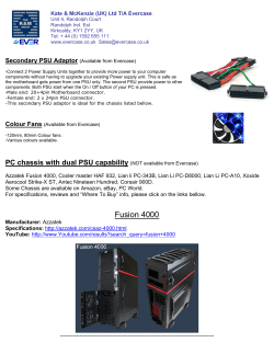
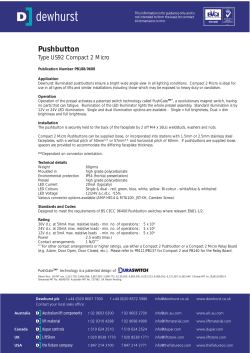
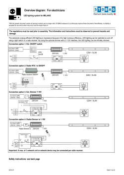
MAX and
LUX
illuminators installation guide
(including IR Covert, IR PLATINUM, HYBRID and Low Voltage Series)
This installation guide provides instructions for installing the RAYMAX and
RAYLUX series illuminators
Installation Steps
1. Mount Illuminator
2. Mount Power Supply Unit (PSU)
3. Connect Illuminator to PSU
4. PSU connections
5. Connect PSU to Mains
Overview
Set Up Steps
1. Position illuminator adjacent to
camera and point towards scene
2. Adjust vertical angle
3. Adjust horizontal angle via Adaptive
Illumination (AI) (if required)
4. Tighten all fixings
Package Contents
1. Illuminator
2. Power Supply (PSU)
RAYMAX / RAYLUX illuminator
Golden Rules:
1.Ensure PSU lid orientation has
warning label in line with glands
(see PSU diagram, right)
2.Ensure operating voltage is correct
for unit being installed
3.DO NOT INPUT MAINS VOLTAGE
INTO LOW VOLTAGE PSU
4. Ensure PSU is fully water tight
g
nin
!
r
wa
PSU
1
Adaptive illumination bolt
LED illuminator
Bracket
LED output cable x2
2.5m (8.2ft)
Photocell
(automatic operation)
LED output 1
LED output 2
Mains input
!
1.5m
Isolate mains before
removing cover
2
Mount PSU to
flat surface
Install in a well
ventilated area
Do not continually
stare at lamp
Specifications subject to change without notice. Installation to be carried out by suitable trained and qualified personnel.
Installation
1m (3.3ft - 29m
9.5ft)
Model d
e
Contac pendent
t Rayled
1
Photocell monitors ambient
lighting conditions
3
Mains Lead
Black = -ve
(polarity sensitive)
2 Mount PSU:
Do not position PSU photocell
facing illuminator or other
direct light sources
2
! CAUTION:Red = +ve
1 Mount illuminator
Mount PSU on wall/flat
surface with glands
facing down
3 Connect Illuminator to PSU:
Installers can extend or
reduce lead length using
appropriate cable and
weather proof box
!
LED Output x2
Mains In
Telemetry Input
4 PSU connections.
Connect telemetry (if required)
5 Connect PSU to Mains
! CAUTION:Ensure cable glands
and PSU lid are water tight by
tightening the fixings
3
Set Up
TARGET
1 Position illuminator adjacent to
camera and point towards scene
(Optional night set-up for
optimum image performance)
2 Adjust vertical angle
!
Max x2
3 Adjust horizontal angle via Adaptive
4 Tighten all fixings
Illumination (AI) (if required)
! CAUTION: Do not fully loosen AI bolt.
Note: Power adjust available if required (see PSU diagrams, pages 8-9)
Match illumination to camera field of view
x
Camera
x
Light
Camera
Light
Camera
Light
Reduces performance
4
May cause hot spots
Best performance
Technical Drawings (Not to scale)
Standard Bracketry
100mm
(4”)
25mm
(1”)
12.5mm
(0.5”)
47mm
(1.9”)
RM/RL 25
36mm
(1.4”)
72mm
(2.8”)
52mm
(2”)
RM/RL 200/100/50
33mm
(1.2”)
RM/RL 300/150
Optional Bracketry
Wall Mount
Ptz Mount
Dome Mount
Pole Mount
5
PSU Specifications
Infra-Red Series PSU
RM300
RM200
RM150
RM100
RM50
RM25
Input
AC 100-230
universal<120W
AC 100-230
universal<80W
AC 100-230
universal<60W
AC 100-230
universal<40W
AC 100-230
universal<20W
AC 100-230
universal<10W
Fuse
2.5A anti-surge
2.5A anti-surge
2.5A anti-surge
2.5A anti-surge
1A anti-surge
1A anti-surge
Typical Output
(Standard)
6.6A @ 13.5V
4.4A @ 13.5V
3.6A @ 13.5V
2.4A @ 13.5V
1A @ 13.5V
0.5A @ 13.5V
Typical Output
(IR PLATINUM)
9A @ 14V
6A @ 14V
6A @ 14V
4A @ 14V
2A @ 14V
1A @ 14V
Typical
Output
(IR Covert)
9A @ 14V
6A @ 14V
6A @ 14V
4A @ 14V
2A @ 14V
1A @ 14V
Adjustable
Power
10% - 100%
10% - 100%
10% - 100%
10% - 100%
10% - 100%
10% - 100%
Weight
2.3 kg
(5.1lbs)
1.85 kg
(4.1lbs)
2.3 kg
(5.1lbs)
1.65 kg
(3.6lbs)
0.9 kg
(2lbs)
0.8 kg
(1.8lbs)
Dimensions
LxWxD
240 x 160 x 81mm 160 x 160 x 81mm 240 x 160 x 81mm 160 x 160 x 81mm 130 x 130 x 60mm 130 x 130 x 60mm
(9.4 x 6.3 x 3.2”) (6.3 x 6.3 x 3.2”) (9.4 x 6.3 x 3.2”) (6.3 x 6.3 x 3.2”) (5.1 x 5.1 x 2.4”) (5.1 x 5.1 x 2.4”)
4 x M4 holes
@ 225 x 123mm
(8.9” x 4.8”)
Drilling
Dimensions
4 x M4 holes
@ 145 x 123mm
(5.7” x 4.8”)
White-Light Series PSU
4 x M4 holes
@ 145 x 123mm
(5.7” x 4.8”)
4 x M4 holes
@ 113 x 113mm
(4.4” x 4.4”)
4 x M4 holes
@ 113 x 113mm
(4.4” x 4.4”)
RL300
RL200
RL150
RL100
RL50
RL25
Input
AC 100-230
universal<120W
AC 100-230
universal < 80W
AC 100-230
universal<60W
AC 100-230
universal <40W
AC 100-230
universal <20W
AC 100-230
universal <10W
Fuse
2.5A anti-surge
2.5A anti-surge
2.5A anti-surge
2.5A anti-surge
1A anti-surge
1A anti-surge
Typical Output
6.3A @ 13.5V
4.2A @ 13.5V
4.2A @ 13.5V
2.8A @ 13.5V
1.4A @ 13.5V
0.7A @ 13.5V
Adjustable
Power
10% - 100%
10% - 100%
10% - 100%
10% - 100%
10% - 100%
10% - 100%
Weight
2.3 kg
(5.1lbs)
1.85 kg
(4.1lbs)
2.3 kg
(5.1lbs)
1.65 kg
(3.6lbs)
0.9 kg
(2lbs)
0.8 kg
(1.8lbs)
Dimensions
LxWxD
240 x 160 x 81mm 160 x 160 x 81mm 240 x 160 x 81mm 160 x 160 x 81mm 130 x 130 x 60mm 130 x 130 x 60mm
(9.4 x 6.3 x 3.2”) (6.3 x 6.3 x 3.2”) (9.4 x 6.3 x 3.2”) (6.3 x 6.3 x 3.2”) (5.1 x 5.1 x 2.4”) (5.1 x 5.1 x 2.4”)
Drilling
Dimensions
4 x M4 holes
@ 225 x 123mm
(8.9” x 4.8”)
4 x M4 holes
@ 145 x 123mm
(5.7” x 4.8”)
HYBRID Series PSU
6
4 x M4 holes
@ 225 x 123mm
(8.9” x 4.8”)
4 x M4 holes
@ 225 x 123mm
(8.9” x 4.8”)
4 x M4 holes
@ 145 x 123mm
(5.7” x 4.8”)
4 x M4 holes
@ 113 x 113mm
(4.4” x 4.4”)
4 x M4 holes
@ 113 x 113mm
(4.4” x 4.4”)
Input
Fuse
Typical Output
Adjustable
Power
Weight
Dimensions
LxWxD
Drilling
Dimensions
AC 100-230
universal<120W
2.5A anti-surge
Model
dependent
Contact Rayled
10% - 100%
2.3 kg
(5.1lbs)
240 x 160 x 81mm
(9.4 x 6.3 x 3.2”)
4 x M4 holes
@ 225 x 123mm
(8.9” x 4.8”)
Low Voltage PSU (LVP) Specification
Infra-Red and WHITE-LIGHT Series PSU
(Excluding Platinum and Covert Series)
300
200
150
100
50
25
Input
x
24V AC/DC
x
24V AC/DC
12/24V AC/DC
12/24V AC/DC
Fuse
x
5A
x
5A
3A
3A
Typical Output
(Infra-Red)
x
4.4A @ 13.5V
x
2.4A @ 13.5V
1A @ 13.5V
0.5A @ 13.5V
Typical Output
(White-Light)
x
4.2A @ 13.5V
x
2.8A @ 13.5V
1.4A @ 13.5V
0.7A @ 13.5V
Adjustable
Power
x
10% - 100%
x
10% - 100%
10% - 100%
10% - 100%
Weight
x
1.85 kg
(4.1lbs)
x
1.65 kg
(3.6lbs)
0.9 kg
(2lbs)
0.8 kg
(1.8lbs)
Dimensions
LxWxD
x
160 x 160 x 81mm
(6.3 x 6.3 x 3.2”)
x
Drilling
Dimensions
x
4 x M4 holes
@ 145 x 123mm
(5.7” x 4.8”)
x
!
160 x 160 x 81mm 130 x 130 x 60mm 130 x 130 x 60mm
(6.3 x 6.3 x 3.2”) (5.1 x 5.1 x 2.4”) (5.1 x 5.1 x 2.4”)
4 x M4 holes
@ 145 x 123mm
(5.7” x 4.8”)
4 x M4 holes
@ 113 x 113mm
(4.4” x 4.4”)
4 x M4 holes
@ 113 x 113mm
(4.4” x 4.4”)
NOTE: Ensure operating voltage is correct for unit being installed.
DO NOT INPUT MAINS VOLTAGE INTO LOW VOLTAGE PSUs.
Power Supply Features
Standard PSU
PREMIUM PSU-PR
•Adjustable photocell
•Adjustable power
•Telemetry input
•Adjustable photocell
•Adjustable power
•Telemetry input
•Photocell following contact, volt
free relay contact - normally open
(day) to normally closed (night)
•12V DC output @ 0.5A
Pulsed PSU - PU
Premium Timer PSU-PRT
•Analogue version
•TTL version
•No photocell
•Adjustable power
• 12V DC output @ 0.5A
•Synchronised with camera
•Adjustable photocell
•Adjustable power
•Telemetry input
•Photocell following contact, volt
free relay contact - normally open
(day) to normally closed (night)
•12V DC output @ 0.5A
• Timer function
7
Power Supply Diagrams (Not to scale)
Infra-Red and White-Light
RM/RL 50/25 Models
(Not to scale)
Photocell
Power Adjust
LED Output x2
(Polarity Sensitive)
Telemetry Input
- requires zero volt,
latched input
Photocell Sensitivity
Mains Input
100V to 230V AC
Auto-Sensing
Infra-Red and White-Light
RM/RL 200/100 Models (Model shown: RM/RL 100 Premium)
(Not to scale)
12V DC power
output
(Premium PSU only)
Photocell following
contact - volt free,
non polarity sensitive
(Premium PSU only)
Telemetry Input
- requires zero volt,
latched input
Photocell
Power Adjust
LED Output x2
(Polarity Sensitive)
8
Photocell Sensitivity
Mains Input
100V to 230V AC
Auto-Sensing
Infra-Red and White-Light
RM/RL 300/150 and Hybrid Models
(Final specification model dependant - model shown: RM/RL 300 Premium)
Note - Hybrid control boards will be labelled IR/WL
Photocell
following contact
- volt free, non
polarity sensitive
(Premium PSU only)
Telemetry Input
requires zero volt,
latched input
Photocell
Sensitivity
Photocell
12V DC Power
Output (Premium
PSU only)
Power Adjust
Up to x3
LED Output
(Polarity Sensitive)
(Model Dependant)
Mains Input
(100V to 230V AC)
Auto-Sensing
9
Trouble Shooting
Ensure all tests are undertaken by a qualified, trained engineer.
Ensure safe working practices are followed at all times
Step 1: Basics
•Check polarity of Infra Red Lamp connection
red=+ve, black=-ve
•Check telemetry link is in
•Check photocell is working
•Check power setting pot fully clockwise
•Check mains input
•Check fuse intact
If OK…
Step 2: Lamp Test
Check voltage of lamp o/p approx 14V (8V for pulsed units)
Check current of lamp – see instructions for correct current setting
To check lamp current (this must be done while both LED panels
are connected to the PSU) remove +ve LED from both lamp supply
cables and connect multimeter set to 10A current in line with the
lamp. [One lead of multimeter in common (COM), other lead into
10A socket of multimeter; set multimeter to 10A readings]. Refer to
PSU Specifications for correct current settings, see pages 6-7.
10
Step 3: Set-up Camera, lens and illumination
Check alignment of lamp
Check camera lens – fully open at night & set correctly
Check model number to Rayled performance specification to ensure
required distance is achievable
Step 4: Call Rayled for further assistance
Note down:
• Model and serial number of illuminator
• Camera make and model
• Lens make and model
If the Rayled lamp is still not delivering the required performance,
please contact us for further assistance.
11
FUSION
illuminators installation guide
This installation guide provides instructions for installing the RAYMAX
and RAYLUX FUSION series illuminators
Installation Steps
1. Mount Illuminator
2. Connect Illuminator to low voltage
power supply
3. Input 12-24V DC/ 24V AC
Optional Set-up (if required)
4. Adjust Power to alter light intensity
5. Adjust Photocell sensitivity
6. Photocell following contact
RM/RL F 100 Setup
7. Telemetry input and photocell
following contact
Overview
Set Up Steps
1. Position illuminator adjacent to
camera and point towards scene
2. Adjust vertical and horizontal
position of lamp to ensure full field
of view illuminated
3. Tighten all fixings
Package Contents
Version: 2
1. Illuminator including mounting
bracket
(RM/RL F 100 only, includes
additional wiring loom)
RAYMAX / RAYLUX
FUSION illuminator
GOLDeN RULeS:
• Ensureoperatingvoltageis
correct for unit being installed
(12-24V DC/ 24V AC)
Bracket
LED illuminator
Back of Unit
‘Command and Control’ Technology™
Cables
RM/RL F 25 & 50
1x four core cable
RM/RL F 25 & 50
DC
AC
Black wire
-
~
Red wire
+
~
Orange and Brown wires=
Photocell following contact.
Volt free output. Non polarity sensitive.
P-cell adjust +
Photocell
adjust
RM/RL F 100
Power adjust +
Power
in
Made in UK
12/24V
AC/DC
input
1x four core cable loom
Power
adjust
Photocell
+ Photocell following contact
DC
AC
Black wire
-
~
Red wire
+
~
RM/RL F 100 is supplied with additional cable loom
White & Brown wires = Photocell following contact.
Volt free output. Non polarity sensitive.
Blue & Black wires = Telemetry connection.
Requires volt free input.
RM/RL F 100
!
1.5m
Power
in
Telemetry
P/C Contact
P-cell adjust +
Power adjust +
Made in UK
Telemetry Input &
Photocell following contact
2
Install in a well
ventilated area
Do not continually
stare at lamp
Specifications subject to change without notice. Installation
to be carried out by suitable trained and qualified personnel.
Installation
1
1
Mount illuminator
2
Connect Illuminator to low voltage power
supply: Installers can extend or reduce lead
length using appropriate cable and weather
proof box
3
Input 12-24V DC/ 24V AC
2
Note:
Red =positive
Black = negative
Optional Set-up (if required) 4 Adjust Power to alter light intensity.
Remove the cover and turn the ‘power adjust’
to alter the intensity of the light level.
Note: Factory set to max. power
RM/RL F 25 & 50
Clockwise=increase
Anticlockwise=decrease
5
P-cell
adjust
+
Power
adjust
Power
in
Adjust Photocell sensitivity. Remove the cover
and turn the ‘photocell adjust’ to alter photocell
sensitivity to ambient lighting condition.
Clockwise=more sensitive
Anticlockwise=less sensitive
+
Made in UK
6
Photocell following contact, volt free relay
contact - normally open (day) to normally
closed (night).
RM/RL F 25 & 50 only
Orange and brown wires =
Photocell following contact
RM/RL F 100 only
Power
in
Telemetry P/C
Contact
P-cell adjust +
Power adjust +
Made in UK
7
RM/RL F 100 only:
Telemetry input and photocell following
contact. Remove cap on telemetry and
photocell following contact connector.
Connect additional cable loom (see below).
RM/RL F 100 only
Blue and black wires =
telemetry connection for remote operation
White and brown wires =
photocell following contact connection
3
Set Up
TARGET
1 Position illuminator adjacent to
camera and point towards scene
(Optional night set-up for
optimum image performance)
3
2 Adjust vertical and horizontal
position of lamp to ensure full field
of view illuminated
Tighten all fixings
Match illumination to camera field of view
x
Camera
x
Light
Camera
Light
Camera
Light
Reduces performance
4
May cause hot spots
Best performance
Technical Drawings (Not to scale)
Standard Bracketry
12.5mm
(0.5”)
47mm
(1.9”)
25mm
(1”)
RM/RL F 25
36mm
(1.4”)
72mm
(2.8”)
25mm
(1”)
RM/RL F 50
52mm
(2”)
104.5mm
(4.1”)
25mm
(1”)
RM/RL F 100
Optional Bracketry
Wall Mount
Ptz Mount
Dome Mount
Pole Mount
5
FUSION Specifications
Infra-Red Series
RM FUSION 100
RM FUSION 50
RM FUSION 25
150m
40m
20m
Consumption
~
35W max
25W max
12W max
Input
12-24V DC/ 24V AC
12-24V DC/ 24V AC
12-24V DC/ 24V AC
Current
2.6A @ 12V
or 1.3A @ 24V
1.5A @ 12V
or 0.75A @ 24V
1A @ 12V
or 0.5A @ 24V
Weight
1.4kg
1.0kg
0.5kg
Environment
IP66
IP66
IP66
Dimensions
LxWxD
180 x 135 x 65 mm
(7 x 5.3 x 2.5”)
135 x 100 x 63 mm
(5.3 x 4 x 2.5”)
75 x 100 x 54mm
(3 x 4 x 2”)
RL FUSION 100
RL FUSION 50
RL FUSION 25
100m
35m
17m
Consumption
~
35W max
25W max
12W max
Input
12-24V DC/ 24V AC
12-24V DC/ 24V AC
12-24V DC/ 24V AC
Current
2.6A @ 12V
or 1.3A @ 24V
1.5A @ 12V
or 0.75A @ 24V
1A @ 12V
or 0.5A @ 24V
Weight
1.4kg
1.0kg
0.5kg
Environment
IP66
IP66
IP66
Dimensions
LxWxD
180 x 135 x 65 mm
(7 x 5.3 x 2.5”)
135 x 100 x 63 mm
(5.3 x 4 x 2.5”)
75 x 100 x 54mm
(3 x 4 x 2”)
Max. Distance
Model dependent
WHITE-LIGHT Series
Max. Distance
Model dependent
Integrated Command and Control™ Technology
RM/RL F 25/50
•Inbuilt photocell for automatic on/off
operation
•Inbuilt power adjust
•Inbuilt photocell level adjust
•Photocell following contact
6
RM/RL F 100
•Inbuilt photocell for automatic on/off operation
•Inbuilt power adjust
•Inbuilt photocell level adjust
•Photocell following contact
•Telemetry input for remote operation
Trouble Shooting
ensure all tests are undertaken by a qualified, trained engineer.
ensure safe working practices are followed at all times.
Step 1: Basics
• CheckpolarityofLampconnection
red=+ve, black=-ve
• Ensurepoweris12-24VDC/24VAC
• Checkphotocellisworking-coverphotocell,lightshouldturnon.
• Ensurepowersupplyissuitablyratedtoproduct-checkpage6for
specifications
If OK…
Step 2: Lamp Test
• Checkcurrentdrawoflampcorrespondstospecificationonpage6
• Checkcurrentoflamp–seeinstructionsforcorrectcurrentsetting
To check lamp current remove +ve (red) lead from power supply and connect
multimeter (set to 10A) in line with the lamp. [One lead of multimeter in common
(COM), other lead into 10A socket of multimeter; set multimeter to read Amps].
Refer to PSU Specifications for correct current settings, see page 6.
Step 3: Set-up Camera, lens and illumination
• Checkalignmentoflamp
• Checkcameralens–fullyopenatnight&setcorrectly
• CheckmodelnumbertoRayledperformancespecificationtoensure
required distance is achievable
Step 4: Call Rayled for further assistance
Note down:
•Modelandserialnumberofilluminator
•Cameramakeandmodel
•Lensmakeandmodel
If the Rayled lamp is still not delivering the required performance, please contact
us for further assistance.
7
© Copyright 2026 Paperzz