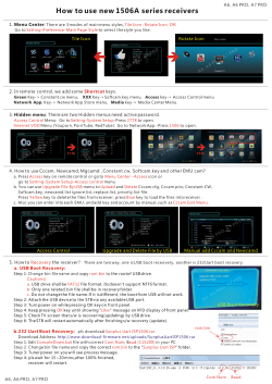
DW1000 USER MANUAL EVK1000 USER MANUAL EVK1000 USER MANUAL HOW TO USE, CONFIGURE AND INTERFACE TO THE DW1000 EVALUATION KIT This document is subject to change without notice © DecaWave Ltd 2014 Version 1.06 Page 1 of 24 EVK1000 User Manual DOCUMENT INFORMATION Disclaimer DecaWave reserves the right to change product specifications without notice. As far as possible changes to functionality and specifications will be issued in product specific errata sheets or in new versions of this document. Customers are advised to check with DecaWave for the most recent updates on this product. Copyright © 2013 DecaWave Ltd LIFE SUPPORT POLICY DecaWave products are not authorized for use in safety-critical applications (such as life support) where a failure of the DecaWave product would reasonably be expected to cause severe personal injury or death. DecaWave customers using or selling DecaWave products in such a manner do so entirely at their own risk and agree to fully indemnify DecaWave and its representatives against any damages arising out of the use of DecaWave products in such safety-critical applications. Caution! ESD sensitive device. Precaution should be used when handling the device in order to prevent permanent damage. REGULATORY APPROVALS This EVK1000 evaluation kit based on DecaWave’s DW1000 IC is intended solely for use by competent engineering personnel for the purposes of evaluating the use of DecaWave’s DW1000 IC in wireless location and communications systems. The EVK1000, as supplied from DecaWave, has not been certified for use in any particular geographic region by any regulatory body governing radio emissions in such regions. The EVK1000 is supplied under the following conditions:     The distribution and sale of the EVK1000 is intended solely for use in future development of devices which may be subject to regulations or other authority governing radio emission. This EVK1000 may not be resold by users for any purpose. The EVK1000 as supplied by DecaWave may not be incorporated directly into user devices or products unless such products undergo the appropriate certification. Operation of the EVK1000 in the development of future devices is at the discretion of the user and the user bears all responsibility for any compliance with regulations laid down by the authority governing radio emissions in the user’s jurisdiction. All products developed by the user incorporating the DW1000 must be approved by the relevant authority governing radio emissions in a jurisdiction prior to the marketing or sale of such products in that jurisdiction. User bears all responsibility for obtaining such approval. If the user has obtained the EVK1000 for any purpose other than those listed above the user should return the EVK1000 to the supplier immediately. FCC NOTICE: This kit is designed to allow (i) product developers to evaluate electronic components, circuitry, or software associated with the kit to determine whether to incorporate such items in a finished product and (ii) software developers to write software applications for use with the end product. This kit is not a finished product and when assembled may not be resold or otherwise marketed unless all required FCC equipment authorizations are first obtained. Operation is subject to the conditions that this device not cause harmful interference to licensed radio stations and that this device accept harmful interference. Unless the assembled kit is designed to operate under Part 15, Part 18 or Part 95 of the FCC Rules, the operator of the kit must operate under the authority of an FCC license holder or must secure an experimental authorization under Part 5 of the FCC Rules. © DecaWave Ltd 2014 Version 1.06 Page 2 of 24 EVK1000 User Manual Table of Contents 1 INTRODUCTION .................................................................................................................................................... 5 1.1 1.2 1.3 2 THE EVK1000 KIT DESCRIPTION ............................................................................................................................ 6 2.1 2.2 2.3 3 DESCRIPTION OF THE EVB1000 BOARD........................................................................................................................ 6 ESSENTIAL ITEMS THAT ARE NOT PART OF THE KIT ............................................................................................................ 7 OPTIONAL ITEMS THAT ARE NOT PART OF THE KIT ............................................................................................................ 7 EVB1000 ON-BOARD RANGING APPLICATION ...................................................................................................... 8 3.1 3.2 3.3 3.4 3.5 3.6 4 OVERVIEW .............................................................................................................................................................. 5 DOCUMENT LAYOUT ................................................................................................................................................. 5 EXTERNAL REFERENCES.............................................................................................................................................. 5 INTRODUCTION ........................................................................................................................................................ 8 ANTENNA CONNECTION ............................................................................................................................................. 8 POWERING THE EVB1000......................................................................................................................................... 8 EVB1000 FUNCTIONAL MODES .................................................................................................................................. 9 EVB1000 OPERATIONAL MODES .............................................................................................................................. 10 READY TO GO?....................................................................................................................................................... 10 EVB1000 CONTROL WITH AN EXTERNAL APPLICATION .......................................................................................12 4.1 INTRODUCTION ...................................................................................................................................................... 12 4.2 “DECARANGING” PC APPLICATION ............................................................................................................................ 12 4.3 EXTERNAL APPLICATION CONTROL OF THE DW1000 VIA THE USB INTERFACE (J5) ............................................................. 13 4.4 EXTERNAL APPLICATION CONTROL OF THE DW1000 VIA THE EXTERNAL SPI HEADER (J6) ..................................................... 13 4.5 EVB1000 OPTIONS WHEN USING “DECARANGING” PC APPLICATION .............................................................................. 14 4.5.1 Using an external application to control both EVB1000 units ...................................................................... 15 4.5.2 Using one externally controlled EVB1000 with one on-board controlled EVB1000 ...................................... 15 5 EVALUATING THE PERFORMANCE OF THE DW1000 USING THE EVK1000 ............................................................16 5.1 5.2 5.3 5.4 INTRODUCTION ...................................................................................................................................................... 16 EVALUATING RANGE PERFORMANCE ........................................................................................................................... 16 EVALUATING RANGING ACCURACY ............................................................................................................................. 17 EVALUATING DW1000 POWER CONSUMPTION ........................................................................................................... 17 6 TROUBLESHOOTING GUIDE .................................................................................................................................19 7 EVB1000 BOARD DETAILS ....................................................................................................................................20 7.1 OFF-BOARD CONNECTOR HEADERS............................................................................................................................. 20 7.1.1 J1 – SMA antenna connector ........................................................................................................................ 20 7.1.2 J4 – JTAG connector ...................................................................................................................................... 20 7.1.3 J5 – Micro USB connector.............................................................................................................................. 20 7.1.4 J6 – External SPI connector ........................................................................................................................... 21 7.1.5 J7 – External DC supply ................................................................................................................................. 21 7.2 ON-BOARD SWITCH FUNCTIONS ................................................................................................................................ 22 7.2.1 S1 .................................................................................................................................................................. 22 7.2.2 S2 .................................................................................................................................................................. 22 7.2.3 S3 .................................................................................................................................................................. 23 7.2.4 SW1 ............................................................................................................................................................... 23 7.3 ON-BOARD 2-PIN JUMPER FUNCTIONS ........................................................................................................................ 23 7.4 ON-BOARD 3-PIN HEADERS WITH JUMPER FUNCTIONS ................................................................................................... 24 7.4.1 J2 and J3 functions ........................................................................................................................................ 24 7.4.2 J8 and J9 functions ........................................................................................................................................ 24 © DecaWave Ltd 2014 Version 1.06 Page 3 of 24 EVK1000 User Manual List of Tables TABLE 1: EXTERNAL REFERENCES AND PUBLICATIONS ........................................................................................................................ 5 TABLE 2: POWER OPTION SETTINGS ............................................................................................................................................... 9 TABLE 3: OPERATIONAL MODES CONFIGURATION DETAILS................................................................................................................ 10 TABLE 4: MAIN EVALUATION PARAMETERS OF INTEREST .................................................................................................................. 16 TABLE 5: FACTORS INFLUENCING COMMUNICATIONS RANGE ............................................................................................................ 16 TABLE 6: J1 PIN OUT ................................................................................................................................................................ 20 TABLE 7: J4 PIN-OUT ................................................................................................................................................................ 20 TABLE 8: MICRO USB CONNECTOR PIN-OUT ................................................................................................................................. 20 TABLE 9: J6 PIN-OUT ............................................................................................................................................................... 21 TABLE 10: J7 PIN-OUT .............................................................................................................................................................. 21 TABLE 11: S1 SWITCH CONFIGURATION DESCRIPTIONS .................................................................................................................... 22 TABLE 12: S2 SWITCH CONFIGURATION DESCRIPTIONS .................................................................................................................... 22 TABLE 13: S3 SWITCH CONFIGURATION DESCRIPTIONS .................................................................................................................... 23 TABLE 14: SW1 ARM RESET BUTTON ......................................................................................................................................... 23 TABLE 15: J10 FUNCTION ......................................................................................................................................................... 23 TABLE 16: J2 AND J3 FUNCTIONS ............................................................................................................................................... 24 TABLE 17: J8 AND J9 FUNCTIONS ............................................................................................................................................... 24 List of Figures FIGURE 1: EVK1000 CONTENTS................................................................................................................................................... 6 FIGURE 2: THE TWO SIDES OF THE EVB1000 SHOWING MAIN COMPONENTS ........................................................................................ 7 FIGURE 3: EVB1000 POWER SUPPLY OPTIONS ................................................................................................................................ 8 FIGURE 4: USB AND DC 3.6V TO 5.5V POWER SOURCE JUMPER CONNECTIONS .................................................................................... 9 FIGURE 5: SWITCH S1-4 TAG / ANCHOR CONFIGURATION ............................................................................................................... 10 FIGURE 6: MODE CONFIGURATION SELECTION ............................................................................................................................... 10 FIGURE 7: EVB1000 POWER ON LCD SCREEN MESSAGES SHOWING SOFTWARE VERSION ...................................................................... 11 FIGURE 8: TAG AND ANCHOR POWER ON LCD MESSAGES................................................................................................................ 11 FIGURE 9: TAG / ANCHOR RANGE DISPLAY .................................................................................................................................... 11 FIGURE 10: LOGICAL VIEW OF THE EVB1000 ............................................................................................................................... 12 FIGURE 11: USB TO SPI CONFIGURATION .................................................................................................................................... 13 FIGURE 12: EXTERNAL APPLICATION CONTROL USING USB INTERFACE ............................................................................................... 13 FIGURE 13: S1 AND S2 CONFIGURATION FOR EXTERNAL APPLICATION CONTROL THROUGH USB ............................................................. 13 FIGURE 14: EXTERNAL APPLICATION CONTROL USING SPI EXTERNAL HEADER ....................................................................................... 14 FIGURE 15: EXTERNAL APPLICATION CONTROL WITH KEIL EVALUATION PLATFORM USING SPI EXTERNAL HEADER ........................................ 14 FIGURE 16: BOTH EVB1000’S CONTROLLED BY THE EXTERNAL APPLICATION ...................................................................................... 15 FIGURE 17: ONE EVB1000 CONTROLLED BY THE EXTERNAL APPLICATION .......................................................................................... 15 FIGURE 18: S1 S1-2 AND S1-8 CONFIGURATION FOR THE LONGER RESPONSE TIME .............................................................................. 19 © DecaWave Ltd 2014 Version 1.06 Page 4 of 24 EVK1000 User Manual 1 INTRODUCTION 1.1 Overview The EVK1000 consists of a pair of EVB1000 boards. Each of the pair of EVB1000 boards is configured to run a pre-programmed two-way ranging demonstration application. This “DecaRanging” application controls the DW1000 IC to exchange messages, calculate the time-of-flight, estimate the resultant distance between the two boards and display that result on the on-board display. Only external powering is required for this operation. The boards may optionally be driven via USB interface using a PC version of the “DecaRanging” software, as described in section 4.3. Alternatively an external micro-controller system may drive the DW1000 IC directly through its SPI interface made available via the SPI header as described in section 4.4. In addition to demonstrating two-way ranging this kit may be used to evaluate the following DW1000 features:        range ranging precision transmit spectrum power/current consumption multipath immunity blocking immunity antenna options It can also be used as a development platform for the DW1000 allowing you develop your own software and applications. 1.2      Document Layout Section 2 describes the contents of the EVK1000 kit. Section 3 describes the on-board “DecaRanging” application. Section 4 describes using an external application to control the DW1000 on the EVB1000. Section 5 is a brief troubleshooting guide Section 7 provides detailed information on the functions and settings of all on-board switches and jumpers and headers. If you are in any doubt about how to perform any of the steps illustrated in this manual or you are unsure how to proceed, please contact DecaWave ([email protected]) and we will be happy to advise you. 1.3 External References Table 1: External references and publications Reference Title/Description 1 “DecaRanging” Demo Application (PC) User Guide 2 DW1000 Data Sheet 3 DW1000 User Manual © DecaWave Ltd 2014 Version 1.06 Page 5 of 24 EVK1000 User Manual 2 THE EVK1000 KIT DESCRIPTION The kit comprises:       2 x EVB1000 boards 2 x Antennae 2 x USB 2.0 cable 2 x Power leads 1 x Quick start guide 2 x Perspex stands 2 x Antenna 2 x EVB1000 2 x Power leads 2 x Micro USB cables Figure 1: EVK1000 contents Please contact DecaWave immediately if any of these items is missing from your kit. 2.1 Description of the EVB1000 board The EVB1000 evaluation board measures 7 cm x 7 cm. Its two sides, identifying the main components, are shown in Figure 2. The front side contains the LCD display which is used to show ranging information and the mode in which the board is operating, the DIP switch (S1), which allows the user to set the mode of operation of the EVB1000 and there are also a number of LEDs. The rear side contains the DW1000 IC, the ARM IC, the ARM reset button, two DIP switches (S2 and S3), the JTAG connection header, the external SPI connection header, and various jumpers and power connectors for configuring the input powering mode. More details on all of these components are contained in section 7. © DecaWave Ltd 2014 Version 1.06 Page 6 of 24 EVK1000 User Manual Figure 2: The two sides of the EVB1000 showing main components 2.2 Essential items that are not part of the kit The following items are not included in the EVK1000 as delivered and are required to operate the kit: 1. Power supply: No power supply units are supplied. The boards may be powered from a bench power supply using the supplied power supply leads, or via a USB power source using the supplied USB cables. These options are described in section 3.3. 2.3 Optional items that are not part of the kit The following items are not included in the EVK1000 as delivered and may be required for further application development using the EVK1000: 1. JTAG interface module: In order to reprogram the on-board ARM Cortex microcontroller, a suitable JTAG adaptor is needed, (e.g. ST microelectronics ST-LINK/V2 in-circuit debugger/programmer). © DecaWave Ltd 2014 Version 1.06 Page 7 of 24 EVK1000 User Manual 3 EVB1000 ON-BOARD RANGING APPLICATION 3.1 Introduction Each of the pair of the EVB1000 boards in the evaluation kit comes with a pre-programmed two-way ranging demonstration software application called “DecaRanging”. This application controls the DW1000 IC to exchange messages, calculate the time-of-flight and estimate & display the resulting distance between two EVB1000 units. To start running the “DecaRanging” demonstration, please follow the steps described below. 3.2 Antenna connection The supplied antenna should be connected to the SMA connector (J1) shown in Figure 2. Best results will be achieved when the planes of the antennae at both ends of the radio link are parallel to each other. It is also possible to use other commercially available UWB antennae with the EVB1000. For references and application advice, please contact DecaWave. 3.3 Powering the EVB1000 The EVB1000 can be powered either via an external DC power supply (or battery) through J7 using the supplied power cable leads or via a standard 5 V 500 mA USB power supply through J5. To change between the two, jumper J8 is used as shown in the Figure 3. Figure 3: EVB1000 power supply options © DecaWave Ltd 2014 Version 1.06 Page 8 of 24 EVK1000 User Manual Table 2: Power option settings J8 (Insert on pins) Comment USB 2&3 The USB port to which you connect the EVB1000 should be capable of supplying at least 250 mA 3.6 V to 5.5 V 1&2 In this mode the externally applied supply is indirectly connected to the on-board circuitry through an LDO regulator Power Source Changes to jumper settings should only be made with the board powered down – under no circumstances should jumper settings be changed while power is applied to the board via any of the possible off-board connectors, or damage to the board may result. For the two power source options the positions of the jumpers are shown in Figure 4. Jumpers J2 and J3 can be used to select whether sections of DW1000 are powered with 1.8 V or 3.3 V, for more details on this operation see Reference [2]. Jumper J10 can be used to measure the current consumption of DW1000. Figure 4: USB and DC 3.6V to 5.5V power source jumper connections 3.4 EVB1000 functional modes The on-board “DecaRanging” application requires one unit to be configured as an “Anchor”, and the other as a “Tag”. These functional modes are controlled with switch, S1-4, as indicated in Figure 5. 1. S1-4 to ON. EVB1000 configured as an “Anchor”. 2. S1-4 to OFF. EVB1000 configured as a “Tag”. © DecaWave Ltd 2014 Version 1.06 Page 9 of 24 EVK1000 User Manual Figure 5: Switch S1-4 Tag / Anchor configuration The EVK1000, by default, has one of the boards configured in Anchor mode and the other in Tag mode. Further details on each function can be found in Reference [1]. 3.5 EVB1000 operational modes The on-board DecaRanging application supports a number of different operational modes. These are chosen to demonstrate the DW1000’s performance in high speed short range and lower speed longer range applications; these are described in detail in Reference [3]. Table 3 below shows the supported configurations; the default EVK1000 configuration, as delivered, is Mode 3. The mode setting is configured with the S1 switches S1-5, S1-6 and S1-7 shown in Figure 6 below. Table 3: Operational modes configuration details S1-5 S1-6 S1-7 Mode Channel Data Rate PRF Preamble Preamble Code OFF ON OFF ON OFF ON OFF ON OFF OFF ON ON OFF OFF ON ON OFF OFF OFF OFF ON ON ON ON 1 2 3 4 5 6 7 8 2 2 2 2 5 5 5 5 110 kbps 6.8 Mbps 110 kbps 6.8 Mbps 110 kbps 6.8 Mbps 110 kbps 6.8 Mbps 16 16 64 64 16 16 64 64 1024 128 1024 128 1024 128 1024 128 3 3 9 9 3 3 9 9 on Non standard SFD Yes No Yes No Yes No Yes No S1 5 6 7 off Figure 6: Mode configuration selection 3.6 Ready to go? Once you have configured the power supply method of your choice and the desired modes of operation and configuration, the board can be powered up. LED 0 will illuminate to indicate that power is applied. You and now ready to begin using your EVK1000 ranging demonstration. The two units will initialise and start the ranging exchange. The messages you will see on the LCD screen during this process are shown in Figure 7, Figure 8, and Figure 9 below. LED 5 will illuminate in Anchor mode whereas LED 6 will illuminate in © DecaWave Ltd 2014 Version 1.06 Page 10 of 24 EVK1000 User Manual Tag mode. After a few moments the calculated range will be displayed on the LCD. For more details on the “DecaRanging” application please consult Reference [1]. DECAWAVE DECAWAVE RANGE Version X.YY Version X.YY Figure 7: EVB1000 power on LCD screen messages showing software version Figure 8: Tag and Anchor power on LCD messages Figure 9: Tag / Anchor range display © DecaWave Ltd 2014 Version 1.06 Page 11 of 24 EVK1000 User Manual 4 EVB1000 CONTROL WITH AN EXTERNAL APPLICATION 4.1 Introduction The EVB1000 has two configuration options which enable an external application to control the DW1000. These are: 1. Using the USB connection (J5). An external application (e.g. DecaWave’s “DecaRanging” PC application) can use the on-board USB to SPI application, to control the DW1000 IC. This is described in section 4.3. 2. Using the external SPI header (J6). This allows a software application running on an external microcontroller or a PC to directly interface with the DW1000 SPI bus. This is described in section 4.4. As the DW1000 is controlled via an SPI interface any external controller wishing to control the DW1000 transceiver must use SPI for direct communication with the chip. J1 Antenna Connector WAKEUP IRQn J7 +3V6 / +5V5 DC DW1000 SUBSYSTEM R41 (DNF / 0Ω) R43 (DNF / 0Ω) SPI I/F POWER SUBSYSTEM / POWER SOURCE SELECTION Always Connected ARM SUBSYSTEM J6 SPI I/F to external computer S2 +5 V DC input from USB J5 USB Connector Figure 10: Logical view of the EVB1000 4.2 “DecaRanging” PC application The on-board “DecaRanging” application that comes pre-programmed on the EVB1000 ARM microcontroller has an equivalent PC application which can be connected to the EVB1000 via the micro USB, to control the DW1000 from a PC. © DecaWave Ltd 2014 Version 1.06 Page 12 of 24 EVK1000 User Manual The “DecaRanging” PC application is available from DecaWave. The description of the “DecaRanging” application is beyond the scope of this manual and is described in Reference [1]. 4.3 External application control of the DW1000 via the USB interface (J5) In this mode of control the on-board USB to SPI application acts as a USB slave virtual COM port. It translates the COM port commands into SPI transactions to the DW1000. To enable the USB to SPI application the EVB1000 needs to have the S1 switch S1-3 set to the off position. Figure 11: USB to SPI configuration DECAWAVE USB to SPI DECAWAVE USB to SPI J5 USB Connector Figure 12: External application control using USB interface 4.4 External application control of the DW1000 via the external SPI header (J6) In this mode of control the on-board ARM processor is not used and it should be disabled and disconnected from the DW1000 SPI bus (switch S1 and S2 should be all in the off position). Figure 13: S1 and S2 configuration for external application control through USB The pin-out of the external SPI connection header J6 has been arranged to be compatible with that of the “Cheetah” series of SPI to USB converters provided by TotalPhaseTM. For more details on the external SPI connector pin out see section 7. Using one of these converters it is possible to control the DW1000 directly from a PC. The “DecaRanging” PC application supports this operation; further details are described in Reference [1]. © DecaWave Ltd 2014 Version 1.06 Page 13 of 24 EVK1000 User Manual Cheetah PSU J6 SPI header Figure 14: External application control using SPI external header Other microprocessor platforms may also be used to control the DW1000. An example using the Keil evaluation platform (MCBSTM32C) is shown below. The ARM SPI1 bus is connected to the EVB1000 SPI header J6. The DW1000 IRQ line is also connected to a GPIO of the ARM processor. For more details on the external SPI connector pin out see section 7. SPI & IRQ signals PSU J6 SPI header Figure 15: External application control with Keil evaluation platform using SPI external header 4.5 EVB1000 options when using “DecaRanging” PC application The hardware setup necessary to allow you use your EVB1000 with the “DecaRanging” PC application is covered in section 4 of this manual. There are two options: 1. Using the external application to control both EVB1000 units. 2. Using the external application to control one of the pair of the EVB1000 units. © DecaWave Ltd 2014 Version 1.06 Page 14 of 24 EVK1000 User Manual 4.5.1 Using an external application to control both EVB1000 units In this configuration both of the two EVB1000s are controlled by the “DecaRanging” PC application further details are described in Reference [1]. USB SPI & USB power USB SPI & USB Power Figure 16: Both EVB1000’s controlled by the external application 4.5.2 Using one externally controlled EVB1000 with one on-board controlled EVB1000 In this configuration one of the two EVB1000s in the “DecaRanging” demonstration runs the “DecaRanging” application from the on-board ARM microcontroller while the other EVB1000 is controlled from a PC which has “DecaRanging” Installed. USB SPI & USB power PSU Figure 17: One EVB1000 controlled by the external application Make sure that the channel configuration settings in the “DecaRanging” PC application are identical to the mode used on the other EVB1000. © DecaWave Ltd 2014 Version 1.06 Page 15 of 24 EVK1000 User Manual 5 EVALUATING THE PERFORMANCE OF THE DW1000 USING THE EVK1000 5.1 Introduction There are three main parameters that evaluators of the DW1000 are typically interested in evaluating using the EVK1000: Table 4: Main evaluation parameters of interest Parameter Description Communications range What is the maximum range between the two nodes in the kit over which communications is successfully maintained and what operating mode yields that longest range? Ranging accuracy What is the accuracy of ranging measurements between the two nodes in the kit and how does this vary with operating parameters? Power consumption What is the power consumption of the DW1000 in various modes of operation and what mode yields the lowest power consumption? Each of these is examined individually in the following sections. 5.2 Evaluating range performance To evaluate the range performance of the DW1000 the most widely used approach is to:   First verify the line-of-sight (LOS) range where there is a clear line of sight between the two nodes. Do this by leaving one node stationary and moving the other node away from it until ranging updates stop Then investigate the non-line-of-sight (NLOS) performance by introducing various obstructions between the two nodes. A more systematic approach can be adopted using the PC base DecaRanging software and monitoring the error counts as described in the DecaRanging user manual as the distance between the nodes is increased. There are a number of factors that influence communications range. These are described in detail in the DW1000 data sheet & user manual so it’s not necessary to go into them in great detail here. In summary, we can say: Table 5: Factors influencing communications range Influencing factor Effect Channel center frequency Lower frequencies propagate further than higher frequencies so to maximise range the lowest possible channel frequency should be selected (Channel 1: 3.5 GHz) Channel bandwidth A wider channel bandwidth allows more energy to be transmitted into the channel than a narrower bandwidth. To maximise range the widest channel bandwidth should be used. In reality in the DW1000, because the first wideband channel is at 4 GHz while the lowest frequency channel is at 3.5 GHz the benefit due to the increased bandwidth at 4 GHz is offset by the higher center frequency and better results are achieved at channel 1. © DecaWave Ltd 2014 Version 1.06 Page 16 of 24 EVK1000 User Manual Influencing factor Effect Data rate Lower data rates have longer range than higher data rates so to maximise range the lowest data rate (110 kbps) should be selected. Preamble length Generally speaking long range operation requires a long preamble length to give the receiver as long as possible to “train” to the incoming signal. The preamble length needs to be chosen in conjunction with the data rate. There is no point is using a very long preamble with a fast data rate at long range because the receiver will not be able to receive the data irrespective of the length of the preamble. However at slow data rates longer preambles give an increase in operating range. To maximize range, a slow data rate in conjunction with a long preamble (2048) should be chosen. PRF The pulse repetition frequency has a very small impact on communications range with 64 MHz PRF giving marginally better performance than 16 MHz PRF As described in section 3.5 the EVK1000 has a number of preprogrammed modes of operation that are selectable via switch S1. The EVK1000 comes pre-configured to Mode 3. This is the pre-programmed mode of operation with the longest range. It uses the lowest frequency pre-programmed channel (channel 2), the slowest data rate (110 kbps) and the longest pre-programmed preamble (1024). Even longer range is possible when using the external DecaRanging PC application to control both nodes as described in section 4.5.1. To achieve the maximum range possible both nodes should be configured to channel 1 (3.5 GHz center frequency), 2048 preamble, 64 MHz PRF and 110 kbps data rate. In a custom design using the DW1000 it is possible to further extend the range by making various choices in terms of hardware configuration including the use of TCXO clock sources, antennas with gain and so on. Please consult the DW1000 data sheet and DW1000 user manual for further information. 5.3 Evaluating ranging accuracy In order to precisely determine the ranging accuracy of the DW1000 it is necessary to adopt a systematic approach to the evaluation. The process normally used by DecaWave to do this is to place the two nodes at a known physical distance apart, take multiple measurements using DecaRanging software (typically up to a 1000 ranges per physical distance), plot those measurements and calculate the mean and standard deviation of the measured values. This process can be repeated for as many physical distances as are required for the intended application. The logging function in the PC based DecaRanging software can be useful for the recording of data from multiple ranging exchanges. 5.4 Evaluating DW1000 power consumption The EVB1000 has been designed to allow the user to measure the current consumed by the DW1000 while operating. The supply to the DW1000 section of the EVB1000 has been isolated from the supply to the remainder of the board and these two sections are connected via a jumper at J10. When operating the EVB1000 normally, a jumper is inserted at J10 to connect these two parts of the circuit together. © DecaWave Ltd 2014 Version 1.06 Page 17 of 24 EVK1000 User Manual In order to measure the current consumption of the DW1000 then it is necessary to remove the jumper at J10 and either: 1. Connect an Ammeter directly across the two pins of J10; or 2. Connect a low value resistor across the pins of J10 (typically this would be in the region of 0.5 to 1 Ohm) and use a Voltmeter across that resistor to derive the current passing through it. Unless a sophisticated instrument is used in the measurement process (that can record currents / voltages in real time to a resolution of microseconds) then the current measured using the methods above will be the average operating current. Current consumption of the DW1000 is very dependent on the operating state of the device. The lowest power pre-programmed mode on the EVK1000 is mode 1. This is not the lowest possible power consumption with the DW1000. The various operating states of the DW1000 are described in detail in the DW1000 data sheet and user manual and it is recommended that the user familiarize themselves with these various operating states, their associated current consumptions and the various ways they can be used to minimize the power consumption of the DW1000. Using the EVK1000 with DecaRanging PC software is not power efficient because of the latencies involved in communicating with the PC. This means that the DW1000 is in an active state for longer than would be necessary in an embedded environment. Power consumption measurements made while a node is being controlled by PC based DecaRanging are not representative of power consumption in a real-world application. © DecaWave Ltd 2014 Version 1.06 Page 18 of 24 EVK1000 User Manual 6 TROUBLESHOOTING GUIDE  No ranging when using “DecaRanging” PC application with one EVB1000 and ARM application on the other EVB1000. o o Make sure that the channel configuration settings in the “DecaRanging” PC application are identical to the mode used on the other EVB1000. If channel configuration settings are the same but the Anchor does not report any TX frames, a longer response time might be needed. Further details are described in Reference [1] (the ARM controlled EVB needs to have S1-2 in the OFF position and S1-8 in the ON position). Figure 18: S1 S1-2 and S1-8 configuration for the longer response time   LCD shows “ERROR INIT FAIL” message. Check that all switches in S2 are in the ON position. Range reads 0.00 m: press the reset button or disconnect and reconnect power Note: To help investigate any potential issues the voltages on J2 and J3 should be either 3.3 V or 1.8 V after power up, depending on which configuration is used as specified in Reference [2]. The voltage on J9 should be 3.3 V. © DecaWave Ltd 2014 Version 1.06 Page 19 of 24 EVK1000 User Manual 7 EVB1000 BOARD DETAILS This section gives further details of the EVB1000 including the pin-outs of all connectors and the function of all the on-board switches and Jumpers. 7.1 7.1.1 Off-board connector headers J1 – SMA antenna connector External antenna connector Table 6: J1 pin out 7.1.2 Pin Function J1-Centre RF signal J1-Body Ground J4 – JTAG connector The JTAG connector is intended for connection to an external ARM debug interface / development toolset. DIL Header, 20 pin, 0.1” pitch. Table 7: J4 pin-out Function 7.1.3 Pin Pin Function VCC 1 2 VCC JTRST 3 4 GND J TDI 5 6 GND J TMS 7 8 GND J TCK 9 10 GND Pulled to GND via 10kΩ resistor 11 12 GND J TDO 13 14 GND ARM_RESET 15 16 GND Pulled to GND via 10kΩ resistor 17 18 GND Pulled to GND via 10kΩ resistor 19 20 GND J5 – Micro USB connector This is the micro USB connector. Table 8: Micro USB connector pin-out Pin Function J5-1 VSUB +5 V IN J5-2 USBDM to ARM GPIO PA11 © DecaWave Ltd 2014 Version 1.06 Page 20 of 24 EVK1000 User Manual Pin 7.1.4 Function J5-3 USBDP to ARM GPIO PA12 J5-4 ID to ARM GPIO PA10 J5-5 GND J6 – External SPI connector The external SPI connector is intended for connection to an external microcontroller or to a PC via a USB to SPI converter (The pin-out of has been arranged to be compatible with that of the “Cheetah” series of SPI to USB converters provided by TotalPhaseTM), DIL Header, 10 pin, 0.1” pitch. Table 9: J6 Pin-out Function Pin Pin SS2 1 2 GND SS3 3 4 IRQ (fit R43, 0Ω) MISO - SPI Data in from PC / External Micro 5 6 Not Connected SCK - SPI Clock from PC / External Micro 7 8 MOSI - SPI Data out to PC / External Micro SS1 9 10 GND 7.1.5 Function J7 – External DC supply Optional external DC power supply pin. SIL 2 pin 0.1” pitch Table 10: J7 pin-out Pin © DecaWave Ltd 2014 Function J7-1 (GND) Ground J7-2 (+VE) DC supply can be from +3.6 V to +5.5 V Version 1.06 Page 21 of 24 EVK1000 User Manual 7.2 On-board switch functions 7.2.1 S1 S1 is a SPST 8-way switch. Its various functions are described in the table below. Table 11: S1 switch configuration descriptions Switch Off function On function S1-1 Disables ARM booting Enables ARM booting S1-2 Disable fast onboard ranging Enable fast onboard ranging S1-3 Enable USB to SPI application Disable USB to SPI application S1-4 Enable DecaRanging Tag function Enable DecaRanging Anchor function Switches between on-board “DecaRanging” Anchor and Tag functionality. S1-5 Operational mode selection Operational mode selection See EVB1000 operational modes for the functionality of this switch S1-6 Operational mode selection Operational mode selection See EVB1000 operational modes for the functionality of this switch S1-7 Operational mode selection Operational mode selection See EVB1000 operational modes for the functionality of this switch S1-8 Disable remote response time configuration Enable remote response time configuration If enabled, the “DecaRanging” PC application can be used to modify the default 150 ms response time in the embedded “DecaRanging” application. 7.2.2 Description If the onboard ARM functionality is not required this switch can be turned off to disable ARM booting. This switch is used to enable fast two-way ranging with the response time is set to 5 ms. If turned off the response time is set to 150 ms. When switched off, the USB to SPI application runs on the onboard ARM to enable “DecaRanging” PC application to control the DW1000. S2 S2 is a SPST 6-way switch. Its various functions are described in the table below. It disables the DW1000 SPI bus connections to the onboard ARM processor. Table 12: S2 switch configuration descriptions Switch ALL Off function All On function Description S2 Disables ARM SPI connection to DW1000 Enables ARM SPI connection to DW1000 If the onboard ARM functionality is not required this switch can be turned off to disable ARM SPI connection to the DW1000. © DecaWave Ltd 2014 Version 1.06 Page 22 of 24 EVK1000 User Manual 7.2.3 S3 S3 is a SPST 4-way switch. Its various functions are described in the table below. Table 13: S3 switch configuration descriptions Switch Off function On function Description S3-1 Disconnects onboard ARM PA0 GPIO to DW1000 RSTn pin Connects onboard ARM PA0 GPIO to DW1000 RSTn pin If used it allows ARM GPIO PA0 pin to connect to DW1000 RSTn pin. This allows ARM to reset the DW1000. This should be on when running the onboard ARM application. S3-2 Disables LED 0 Enables LED 0 Can be used to enable or disable LED 0. (current consumption measurement) S3-3 Selects DW1000 SPI mode Selects DW1000 SPI mode This switch can be used to select DW1000 SPI mode it is connected to DW1000 GPIO 5 pin. For more information see Reference [2]. S3-4 Selects DW1000 SPI mode Selects DW1000 SPI mode This switch can be used to select DW1000 SPI mode it is connected to DW1000 GPIO 6 pin. For more information see Reference [2]. 7.2.4 SW1 This is the ARM reset button. Table 14: SW1 ARM reset button Switch Pressed Released SW1 Forces hardware reset of ARM processor Allows ARM processor to operate normally 7.3 Description Is used to allow reset the ARM processor. On-board 2-pin jumper functions Table 15: J10 function Jumper J10 In Out Connects main 3.3V power from DW1000 Disconnects main 3.3V power from DW1000 © DecaWave Ltd 2014 Description Enables DW1000 power/current measurement. Version 1.06 Page 23 of 24 EVK1000 User Manual 7.4 On-board 3-pin headers with jumper functions 7.4.1 J2 and J3 functions Table 16: J2 and J3 functions Jumper J2 J3 7.4.2 In pins 1 & 2 In pins 2 & 3 Out Description DW1000 uses 3.3 V supply for VDDLDO DW1000 uses external DC-DC 1V8 supply for VDDLDO as current saving option DW1000 VDDLDO power disconnected For more information see Reference [2]. DW1000 uses 3.3 V supply for VDDLDO2 DW1000 uses external DC-DC 1V8 supply for VDDLDO2 as current saving option DW1000 VDDLDO2 power disconnected For more information see Reference [2]. J8 and J9 functions Table 17: J8 and J9 functions Jumper In pins 1 & 2 In pins 2 & 3 Out J8 Enables EVB1000 powering from J6 Enables EVB1000 powering from J5 EVB1000 is not powered Enables different power configuration options. J9 In this mode the externally applied supply is connected to the onboard circuitry through a 3.3V voltage regulator n/a Voltage regulator is disconnected – EVB1000 is not powered. Must be connected for EVB1000 power. © DecaWave Ltd 2014 Version 1.06 Description Page 24 of 24
© Copyright 2026 Paperzz