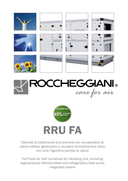
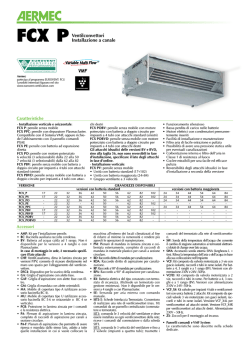
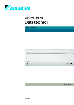
SINGLE PHASE MEDIUM PRESSURE DUCTABLE UNITS WITH ELECTRONICALLY COMMUTATED MOTOR
MF-EC
UNITˆ CANALIZZABILI MONOFASE A MEDIA PRESSIONE CON MOTORE A COMMUTAZIONE ELETTRONICA
®
Climate solutions
I dati contenuti nel presente catalogo possono essere cambiati senza obbligo di preavviso.
All specifications are subject to change without notice.
2
0
INTRODUZIONE
INTRODUCTION
®
MF-EC
Le unità canalizzabili della nuova serie MF-EC con motori a commutazione elettronica brushless nascono dalla crescente richiesta
di prodotti ad elevata efficienza, con ridotti consumi.
Per adattarsi alle molteplici esigenze della clientela i terminali, che sono prodotti sia in configurazione orizzontale che in quella verticale, sono
disponibili in 4 taglie, con batteria principale a 3 o
4 ranghi, alla quale può essere aggiunta una batteria di riscaldamento opzionale a 1 o 2 ranghi (quest’ultima non certificata EUROVENT).
Oltre ai tradizionali sistemi di regolazione, le unità canalizzabili
possono essere anche comandate mediante un sistema di supervisione MAXINET. Con il software MAXINET è possibile monitorare e gestire l’intero impianto di condizionamento.
L’applicazione prevede anche la possibilità di accesso remoto per
garantire la completa interazione col sistema.
A tutela dei propri clienti ATISA aderisce al programma EUROVENT di certificazione delle proprie unità canalizzabili.
1
The new serie of MF-EC ductable units with brushless motors
are high efficiency with great reduction in electrical consumption.
In order to satisfy the wide necessities of the Customers, units are available in horizontal or vertical solution and in 4 sizes, with main coil at 3
or 4 rows, which can be added an optional 1 or
2 rows coil (the 2 rows coil is not EUROVENT
certified).
Beyond the traditional control boxes, the ductable units can also be managed by means of a supervision system
MAXINET. With MAXINET software is possible to manage the
total air conditioning plant. The application includes also the
possibility of remote control access in order to guarantee the
complete interaction with the system.
As guarantee for user, ATISA partecipates at EUROVENT program for certification of ductable units.
CARATTERISTICHE COSTRUTTIVE
MAIN FEATURES
Involucro portante
In lamiera zincata di prima scelta, coibentato internamente con
materiale fonoassorbente ed autoestinguente.
Chassis unit
Manufactured from galvanized sheet first grade, internally insulated
with an acoustic and self-extinguish lining.
Batteria principale di scambio termico
A pacco con tubi in rame mandrinati ed alette in alluminio, collettori in ottone pressofuso con attacchi filettati gas femmina dotati
di valvolina di sfogo aria e tappo di scarico. La batteria è collaudata
alla pressione di 15 Ate ed è fornita con lato attacchi standard SN che può essere invertito, se necessario,
anche in cantiere.
Main heat exchanger
Copper tubes / aluminium fins with collectors manufactured from
die cast brass with female BSP thread connections; each coil is fitted
with a manual air vent and drain plug. The coil is tested at a pressure of 15 Ate and is supplied with left side standard connections that can be easily inverted on site.
Batterie di scambio termico
A pacco con tubi in rame ed alette in alluminio, collettori in ottone pressofuso con attacchi filettati gas femmina dotati di valvolina di sfogo aria e tappo di scarico. La batteria è collaudata alla
pressione di 15 Ate ed è fornita con lato attacchi standard SN che può essere invertito, se necessario,
anche in cantiere.
Heat exchanges
Copper tubes/aluminium fins with collectors manufactured from die
cast brass with female BSP thread connections; each coil is fitted
with a manual air vent and drain plug. The coil is tested at a pressure of 15 Ate and is supplied with left side standard connections that can be easily inverted on site.
Gruppo elettroventilante
• VENTILATORE - A doppia aspirazione con giranti centrifughe
a pale avanti in alluminio, equilibrate staticamente e dinamicamente, direttamente accoppiate al motore.
• MOTORE BRUSHLESS - a magneti permanenti, abbinato a
scheda di controllo che ne monitora costantemente il funzionamento. L’alimentazione elettrica è monofase con tensioni
220-240V e frequenza 50/60 Hz.
Fan section
• FAN – Double inlet type with aluminium centrifugal impellers, forwards blades, statically and dynamically balanced, directly couple
to the motor.
• BRUSHLESS MOTOR – permanent magnets, continuously controlled by electronic control boards. Single phase 220-240V – 50/60
Hz.
Bacinella
Bacinella principale di raccolta condensa in acciaio zincato di
prima scelta (in ABS nelle configurazioni orizzontali), esternamente rivestita con materassino anticondensa autoestinguente.
Main Drain Pan
Manufactured from galvanized steel sheet first grade (ABS for horizontal versions), externally coated with self-extinguish and anticondensate mat.
Filtro rigenerabile
Realizzato in materiale sintetico. È contenuto in un telaio in lamiera zincata dotato di rete protettiva su entrambi i lati.
Filter
Made of syntetic material contained into a galvanized frame with
mesh on both sides.
3
IDENTIFICAZIONE, VERSIONI E LATO IDRAULICI
IDENTIFICATION CODE, VERSIONS AND HYDRAULIC CONNECTIONS SIDE
2
Le unità canalizzabili della serie MF, si identificano con la seguente sigla
alfa/numerica:
MF-EC – xy – bb
serie dell’unità canalizzabile
grandezza dell’unità canalizzabile
numero dei ranghi della batteria principale
versione
MF-EC
x
y
bb
esempio:
:
:
:
:
ductable unit serie
ductable unit size
main coil rows number
version
example:
MF-EC 34 PS
MF-EC :
:
3
4
:
PS
:
MF-EC
MF ductable units serie, are identified by means of the following
alpha/numerical code:
MF-EC – xy – bb
MF-EC :
:
x
y
:
bb
:
®
MF-EC 34 PS
unità canalizzabile
taglia 3
batteria principale a 4 ranghi
versione pensile
MF-EC
x
y
PS
:
:
:
:
ductable unit
size 3
4 rows main coil
horizontal version
SM
FSM
PS
FPS
Lato attacchi idraulici standard
Side of hydraulic standard connections
4
3
PRESTAZIONI
PERFORMANCES
®
MF-EC
Prestazioni con batteria PRINCIPALE - Performances with MAIN coil
MODELLI - MODELS
Portata aria
Air flow
m3/h
Pressione statica
Available static. pr.
Pa
Assorbimento elettrico
Absorbed power
W
Livello di potenza
sonora (asp. + irr.)
Sound power level
(inlet + rad)
dB(A)
Livello di Potenza
sonora (mandata)
Sound power level
(outlet)
dB(A)
MIN (E) - 2V
4V
MED (E) - 6V
8V
MAX (E) - 10V
MIN (E) - 2V
4V
MED (E) - 6V
8V
MAX (E) - 10V
MIN (E) - 2V
4V
MED (E) - 6V
8V
MAX (E) - 10V
MIN (E) - 2V
4V
MED (E) - 6V
8V
MAX (E) - 10V
MIN (E) - 2V
4V
MED (E) - 6V
8V
MAX (E) - 10V
23
290
340
390
440
490
28
38
50
64
78
21
30
41
56
73
49
54
58
61
64
43
48
52
55
58
24
270
320
360
420
460
28
39
50
65
80
17
29
40
54
70
49
53
57
61
63
43
47
51
55
57
33
380
440
510
580
630
29
39
50
62
78
20
32
46
64
80
50
53
58
60
63
44
47
52
54
57
34
350
430
480
540
600
28
40
50
63
77
19
32
43
62
79
49
52
57
59
62
43
46
51
53
56
53
570
680
780
880
990
28
38
50
64
80
33
50
71
105
151
54
58
62
63
67
48
52
56
57
61
54
530
620
730
820
930
28
38
50
65
80
30
46
69
101
145
54
58
62
63
67
48
52
56
57
61
73
800
930
1050
1190
1300
30
40
50
65
77
46
66
95
130
167
56
59
63
65
68
50
53
57
59
62
74
790
900
1030
1160
1260
28
38
50
62
75
46
65
93
127
163
56
58
63
64
68
50
52
57
58
62
Rese termiche in RAFFREDDAMENTO - COOLING capacities
Temperatura aria:
Air temperature:
27°C d.b. - 19°C w.b.
Potenza totale
Total cooling capac.
kW
Potenza sensibile
Sensible capacity
kW
Portata acqua
Water flow
l/h
rp acqua
rp water
kPa
MIN (E) - 2V
4V
MED (E) - 6V
8V
MAX (E) - 10V
MIN (E) - 2V
4V
MED (E) - 6V
8V
MAX (E) - 10V
MIN (E) - 2V
4V
MED (E) - 6V
8V
MAX (E) - 10V
MIN (E) - 2V
4V
MED (E) - 6V
8V
MAX (E) - 10V
1,81
2,07
2,34
2,53
2,69
1,31
1,52
1,73
1,88
2,01
311
356
402
435
462
8,6
11,1
13,7
15,8
19,6
Temperatura acqua:
Water temperature:
1,89
2,21
2,53
2,86
3,05
1,34
1,57
1,81
2,06
2,21
325
380
435
491
524
4,3
6,0
7,8
9,5
10,8
2,54
2,84
3,17
3,32
3,69
1,84
2,07
2,33
2,46
2,75
437
488
545
570
634
8,0
9,7
11,7
12,9
15,6
entrata
inlet
2,67
3,18
3,43
3,68
4,13
1,87
2,24
2,43
2,61
2,95
459
546
589
632
709
10,5
14,0
16,2
18,5
22,9
7°C
uscita
outlet
12°C
3,70
4,40
4,87
5,31
5,68
2,66
3,20
3,57
3,92
4,22
635
756
836
912
975
11,7
16,0
19,4
22,7
26,3
3,95
4,53
5,23
5,71
6,42
2,79
3,21
3,72
4,07
4,61
678
778
898
981
1102
8,1
10,4
13,5
15,8
19,6
4,97
5,52
5,90
6,45
6,86
3,65
4,09
4,40
4,85
5,20
853
948
1013
1108
1178
20,1
24,2
28,1
32,7
36,5
5,55
6,25
6,97
7,62
7,96
3,96
4,48
5,04
5,54
5,82
953
1073
1197
1308
1367
15,1
18,8
22,9
27,0
29,4
Rese termiche in RISCALDAMENTO batteria principale - Main coil HEATING capacities
Temperatura aria:
Air temperature:
20°C
Temperatura acqua:
Water temperature:
MODELLI - MODELS
Potenza termica
Heating capacity
kW
rp acqua
rp water
kPa
MIN (E) - 2V
4V
MED (E) - 6V
8V
MAX (E) - 10V
MIN (E) - 2V
4V
MED (E) - 6V
8V
MAX (E) - 10V
23
2,28
2,59
2,90
3,18
3,45
7,3
9,4
11,6
13,4
16,7
50°C
24
2,39
2,77
3,06
3,48
3,75
3,7
5,1
6,6
8,1
9,2
portata acqua uguale a quella di raffreddamento (27°C db – 19°C wb)
same water flow in cooling (27°C db – 19°C wb)
33
3,03
3,41
3,84
4,22
4,52
6,8
8,2
9,9
11,0
13,3
34
3,16
3,77
4,14
4,56
4,98
8,9
11,9
13,8
15,7
19,5
53
4,58
5,30
5,91
6,50
7,10
9,9
13,6
16,5
19,3
22,4
54
4,78
5,47
6,29
6,93
7,71
6,9
8,8
11,5
13,4
16,7
73
6,03
6,78
7,43
8,16
8,72
17,1
20,6
23,9
27,8
31,0
74
6,72
7,50
8,38
9,22
9,83
12,8
16,0
19,5
23,0
25,0
Rese termiche in RISCALDAMENTO della batteria ausiliaria ad un rango (PX) - Heating capacities of one row additional coil (PX)
Temperatura aria:
Air temperature:
MODELLI - MODELS
Potenza termica
Heating capacity.
kW
Portata acqua
Water flow
l/h
rp acqua
rp water
kPa
MIN (E) - 2V
4V
MED (E) - 6V
8V
MAX (E) - 10V
MIN (E) - 2V
4V
MED (E) - 6V
8V
MAX (E) - 10V
MIN (E) - 2V
4V
MED (E) - 6V
8V
MAX (E) - 10V
20°C
23PX
1,81
2,00
2,19
2,36
2,53
159
177
192
208
222
5,8
6,9
8,1
9,2
10,4
Temperatura acqua:
Water temperature:
24PX
1,73
1,93
2,08
2,29
2,43
152
170
183
202
214
5,3
6,5
7,4
8,8
9,7
(E) Prestazioni certificate EUROVENT - (E) EUROVENT certified performances
33PX
2,44
2,68
2,95
3,20
3,37
215
236
259
281
296
12,2
14,5
17,1
19,8
21,7
entrata
inlet
70°C
uscita
outlet
60°C
34PX
2,31
2,64
2,83
3,06
3,27
203
232
250
269
288
11,1
14,1
16,0
18,3
20,5
53PX
3,77
4,23
4,63
5,00
5,38
332
372
407
440
474
6,1
7,5
8,8
10,1
11,5
54PX
3,59
3,98
4,43
4,78
5,18
316
351
390
420
455
5,6
6,8
8,2
9,3
10,7
73PX
4,70
5,18
5,59
6,04
6,38
414
455
491
531
561
9,0
10,7
12,3
14,1
15,5
74PX
4,66
5,07
5,52
5,94
6,26
410
446
485
523
550
8,9
10,3
12,0
13,7
15,0
4
DIMENSIONI D’INGOMBRO E PESI
DIMENSIONS AND WEIGHTS
SM
VERTICALE senza MOBILE
VERTICALL without CABINET
PS
ORIZZONTALE senza MOBILE
HORIZONTAL without CABINET
®
MF-EC
FSM
VERTICALE senza MOBILE ad aspirazione FRONTALE
VERTICAL without CABINET and FRONT AIR INTAKE
FPS
ORIZZONTALE senza MOBILE ad aspirazione FRONTALE
HORIZONTAL without CABINET and FRONT AIR INTAKE
Dimensioni - Dimensions
MODELLI - MODELS
A
B
C
D
E
F
mm
G
H
I
J
FILTRI - FILTERS
23
700
225
550
56
344
150
720
670
185
15
207 x 658
24
700
225
550
56
344
150
720
670
185
15
207 x 658
33
920
225
550
56
344
150
940
890
185
15
207 x 878
34
920
225
550
56
344
150
940
890
185
15
207 x 878
53
1140
255
580
68
355
157
1160
1110
215
15
235 x 1098
54
1140
255
580
68
355
157
1160
1110
215
15
235 x 1098
73
1140
255
580
68
355
157
1160
1110
215
15
235 x 1098
74
1140
255
580
68
355
157
1160
1110
215
15
235 x 1098
Pesi - Weights
MODELLI - MODELS
SM
PS
FSM
FPS
kg
PX (*)
PX2 (*)
23
24
33
34
53
54
73
74
19,3
20,2
23,0
24,8
30,3
31,4
32,1
34,1
18,7
19,6
22,4
24,2
29,5
30,6
31,2
33,2
19,6
20,5
23,5
25,3
31,0
32,1
32,7
34,7
18,9
19,8
22,6
24,4
29,7
30,8
31,8
33,8
1,1
1,1
1,3
1,3
1,9
1,9
1,9
1,9
1,8
/
2,1
/
3,3
/
3,3
/
(*) Peso della sola batteria - Only coil weight
6
INTERFACCE IDRAULICHE
HYDRAULIC CONNECTIONS
5
®
MF-EC
SM
PS
FSM
FPS
Quote - Quotas
MODELLI - MODELS
A
B
C
D
E
mm
SM-FSM
F
Scarico cond. est - Drain pain ext
PS-FPS
E
F
Scarico cond. int - Drain pain int
ø
PX
G
H
I
J
mm
ø
PX2
G
H
I
J
mm
ø
23
38
433
124
281
170
180
25
215
270
15
1/2”
1/2”
90
462
151
353
1/2”
1/2”
99
468
161
359
1/2”
1/2”
24
44
436
130
284
170
180
25
215
270
15
1/2”
1/2”
101
469
163
360
1/2”
1/2”
/
/
/
/
/
/
34
44
436
130
284
170
180
25
215
270
15
1/2”
1/2”
101
469
163
360
1/2”
1/2”
/
/
/
/
/
/
33
47
438
134
286
170
180
25
215
270
15
1/2”
1/2”
90
462
151
353
1/2”
1/2”
99
468
161
359
1/2”
1/2”
7
53
39
475
153
281
205
205
25
245
275
15
1/2”
1/2”
90
505
179
354
1/2”
1/2”
99
510
188
360
1/2”
1/2”
54
44
478
158
284
205
205
25
245
275
15
1/2”
1/2”
101
511
190
361
1/2”
1/2”
/
/
/
/
/
/
73
39
475
153
281
205
205
25
245
275
15
1/2”
1/2”
90
505
179
354
1/2”
1/2”
99
510
188
360
1/2”
1/2”
74
44
478
158
284
205
205
25
245
275
15
1/2”
1/2”
101
511
190
361
1/2”
1/2”
/
/
/
/
/
/
6
DIMENSIONI E PESI UNITà IMBALLATE
PACKAGING DIMENSIONS AND WEIGHTS
®
MF-EC
Dimensioni imballi delle unità canalizzabili - Packaging dimensions for ductable units
MODELLI - MODELS
A
mm
B
C
23
1090
250
600
24
1090
250
600
34
1310
250
600
33
1310
250
600
53
1310
250
600
54
1310
250
600
73
1530
275
645
74
1530
275
645
Pesi indicativi delle unità canalizzabili imballate - Approximate packaging weights for ductable units
23
24
33
34
53
54
73
74
SM
21,0
22,0
25,0
27,0
32,0
33,0
34,0
36,0
38,0
MODELLI - MODELS
SM + PX
22,0
23,0
26,0
28,0
34,0
35,0
36,0
SM + PX2
23,0
/
27,0
/
36,0
/
37,0
/
PS
20,0
21,0
24,0
26,0
31,0
33,0
33,0
35,0
PS + PX
21,0
22,0
25,0
27,0
33,0
34,0
35,0
37,0
PS + PX2
22,0
/
26,0
/
35,0
/
36,0
/
21,0
22,0
25,0
27,0
33,0
34,0
35,0
37,0
FSM
kg
FSM + PX
22,0
23,0
27,0
28,0
35,0
36,0
37,0
39,0
FSM + PX2
23,0
/
27,0
/
36,0
/
38,0
/
FPS
21,0
21,0
24,0
26,0
32,0
33,0
34,0
36,0
FPS + PX
22,0
23,0
26,0
27,0
34,0
35,0
36,0
38,0
FPS + PX2
22,0
/
26,0
/
35,0
/
37,0
/
8
7
ACCESSORI
ACCESSORIES
®
MF-EC
Sistema di comando a raggi infrarossi costituito da:
Infrared system control costituited of:
TLC/H
Telecomando a raggi infrarossi
TLC/H
Infrared remote control.
RIC
Ricevitore IRPX500 per telecomando.
RIC
Infrared receiver for remote control IRPX500.
SECM
Scheda di regolazione. Deve essere specificato il protocollo: Maxinet, Modbus o Bacnet.
SECM
Electronic card. It must be indicated if Maxinet, Modbus or Bacnet
protocols.
Scatola comandi RDB
Scatola comandi digitale con display, adatta per installazione a bordo
macchina o remota e completa dei seguenti comandi:
• Pulsante ON/OFF;
• Pulsante comando velocità
• Pulsante Menu;
• Selettore impostazione della temperatura.
La scatola comandi, a seconda dei collegamenti, può funzionare con
o senza termostato di minima (SM) e/o sonda acqua (SH) per
change over solo per impianti a 2 tubi. E' inoltre possibile collegare
una sonda aria remota (RS). Il dispositivo è in grado di controllare
una valvola ON/OFF (imp. a 2 tubi), o 2 valvole ON/OFF indipendenti (imp. a 4 tubi). Oltre ad includere la funzione di destratificazione, la scatola comandi è prevista per il collegamento ad un
contatto finestra.
RDB control box
Digital control box with display, suitable for board or remote installation and including the following controls:
• ON/OFF switch;
• Fan speed control switch;
• Menu switch;
• Setting temperature selector.
According to the wiring connections, control box can work with or without minimum temperature sensor (SM) and/or a water temperature sensor (SH) for change over for 2 pipe plants only. It is also
possible to connect a remote air temperature sensor (RS).The control
box is able to manage one ON/OFF valve (2 pipes plants), or to manage 2 independent ON/OFF valves (4 pipes plants). The control box
is complete of destratification function and includes a window contact.
WS - Basetta per scatola comandi
WS - Sideboard for control box
E' un accessorio ideato per installare la scatola comandi
a parete.
It is an accessory designed to install the control box at the
wall.
WM – Piastra metallica per scatola comandi
WM – Metal plate for control box
Supporto per scatola comandi per installazione a bordo
macchina nelle versioni senza mobile.
Deve essere utilizzata unitamente alla basetta WS.
Support for control box for board installation in the versions without cabinet.
It has to be used together WS side board.
SH - Sonda acqua per change over
SH - Water sensor for change over
Consente di invertire automaticamente il ciclo di funzionamento del ventilconvettore da invernale a estivo
e viceversa.
Per il corretto funzionamento del sistema è necessario
che la sonda sia installata sul tubo ingresso acqua.
Può assolvere anche alla funzione di sonda di minima.
Permits to automatically invert the working cycle of the
fan coil from winter to summer and vice-versa.
For the correct working of the system, it is necessary that
the water sensor for change over is installed on the water
inlet collector. It can be also used as minimum temperature sensor.
SM - Sonda di minima
SM - Water temperature sensor
In regime invernale è un dispositivo che evita il funzionamento del ventilatore con temperature dell’acqua
troppo basse evitando conseguentemente fenomeni di
shock termico.
Deve essere installata a contatto del collettore d’ingresso acqua tramite la fascetta fornita in dotazione.
In winter mode, it is a sensor that stops the workin of the
fan with low temperatures in order to avoid consequent
thermal shock.
It must be installed in contact with the water inlet collector by means of a clamp supplied together the water temperature sensor.
RS - Sonda remota
RS - Remote sensor
Rileva la temperatura dell’aria ambiente in luogo del
sensore presente nella scatola comandi.
Deve essere installato sul lato aspirazione aria del ventilconvettore.
It gathers the room air temperature instead of the sensor
fitted into the control box.
It must be installed on the air inlet side of the fan coil.
SKH – Sonda aria / acqua per TLC
SKH – Sonda aria / acqua per TLC:
Sonda aggiuntiva per TLC con funzione di change over
o di termostato di minima.
Additional sensor for TLC for change over or minimum
temperature sensor.
9
7
ACCESSORI
ACCESSORIES
®
MF-EC
PX
Batteria di riscaldamento supplementare a 1 rango.
PX
1 row additional heating coil.
PX2
Batteria di riscaldamento supplementare a 2 ranghi.
PX2
2 rows additional heating coil.
BS – BSP (solo per modelli orizzontali)
Bacinella secondaria in materiale plastico termoresistente, per raccolta condensa sul lato collettori (per modelli verticali).
BS – BSP (horizontal models only)
Secondary drain pan made of plastic material for condensate discharge on collector’s side (vertical models only).
SC
Pompa di scarico condensa con controllo di livello a 3 posizioni.
SC
Condensate discharge pump with 3 position level control.
VA2
VA2
Valvole di regolazione ON/OFF (Ø1/2”) a 2 vie complete di attuatori (230V).
2 way ON/OFF regulation valves (Ø1/2”) complete of actuators
(230V).
VA3
VA3
Valvole di regolazione ON/OFF (da Ø1/2”) a 3 vie
complete di attuatori (230V).
3 way ON/OFF regulation valves (Ø1/2”) complete of actuators
(230V).
R2V
Kit raccordi per valvole a 2 vie.
R2V
Valve’s connections kit for 2 way valves.
R3V
Kit raccordi per valvole a 3 vie.
R3V
Valve’s connections kit for 3 way valves.
PMM (mandata) – PMR (ripresa)
Plenum di mandata (coibentato internamente) o ripresa realizzato
in lamiera zincata spess. 8/10, predisposto per attacchi circolari.
PMM (supply) – PMR (return)
Supply (internally insulated) or return air plenum in galvanized steel
sheet 8/10 thickness, forecasted for circular duct connections.
PR (ripresa)
Plenum di ripresa realizzato in lamiera zincata spess. 8/10, predisposto per attacco frontale.
PR (return)
Return air plenum in galvanized steel sheet 8/10 thickness, forecasted
for frontal duct.
10
7
ACCESSORI
ACCESSORIES
®
MF-EC
Tabella abbinamenti accessori - Accessories matching table
ACCESSORIO
ACCESSORY
TLC
RDB
WS
WM
SH
SM
RS
SKH
PX
PX2
BS
BSP
SC
VA2
VA3
R2V
R3V
PMM
PMR (*)
PR (*)
MF-EC 23
MF-EC 24
MF-EC 33
•
•
•
•
•
•
•
•
•
•
•
•
•
•
•
•
•
•
•
•
•
•
•
•
•
•
•
•
•
•
•
•
•
•
•
•
•
•
•
•
•
•
•
•
•
•
•
•
•
•
•
•
•
•
•
•
•
•
•
Taglia - Size
MF-EC 34
MF-EC 53
•
•
•
•
•
•
•
•
•
•
•
•
•
•
•
•
•
•
•
(*) Solo per versione PS - For PS version only
11
•
•
•
•
•
•
•
•
•
•
•
•
•
•
•
•
•
•
•
•
MF-EC 54
MF-EC 73
MF-EC 74
•
•
•
•
•
•
•
•
•
•
•
•
•
•
•
•
•
•
•
•
•
•
•
•
•
•
•
•
•
•
•
•
•
•
•
•
•
•
•
•
•
•
•
•
•
•
•
•
•
•
•
•
•
•
•
•
•
•
CERTIFICATI
CERTIFICATES
®
MF
© Copyright 2026 Paperzz