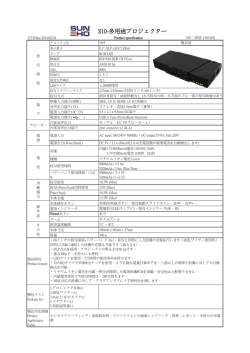
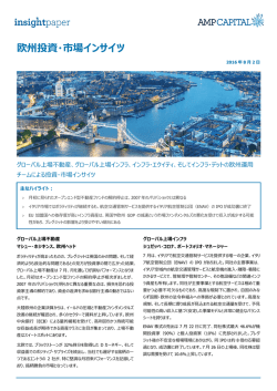
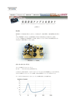
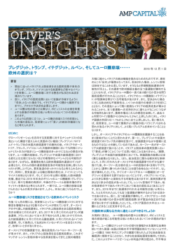
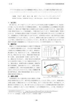
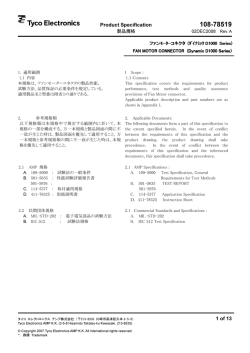
Product Specification
108-78453
製品規格
27MAR2007 Rev. A
DDR-II DIMM Socket 240 Positions SMT Type
1. 適用範囲
1.1 1.1 内容
1. Scope :
1.1 Contents
本規格はDDR-II ディム・ソケット240極SMTと金めっき This specification covers the requirements for product
DDR-II ディムとの組み合わせ使用時の製品性能、試験 performance, test methods and quality assurance
方法、品質保証の必要条件を規定している。
provisions of DDR-II DIMM Socket 240 Positions SMT
Combine to Gold Plating DDR-II DIMM.
2. 参考規格類
2. Applicable Documents:
以下規格類は本規格中で規定する範囲内に於いて、本規 The following documents form a part of this
格の一部を構成する。万一本規格と製品図面の間に不一 specification to the extent specified herein. In the event
致が生じた時は、製品図面を優先して適用すること。万一 of conflict between the requirements of this
本規格と参考規格類の間に不一致が生じた時は、本規格 specification and the product drawing, the product
を優先して適用すること。
drawing shall take precedence.
In the event of conflict
between the requirements of this specification and the
referenced documents, this specification shall take
precedence.
2.1 AMP 規格
2.1
A. 109-5000 : 試験法の一般条件
A. 109-5000
AMP Specifications :
Test Specification, General
Requirements for Test Methods
B. 501-5831 : 試験報告書
2.2
民間団体規格
A. MIL-STD-202
B. 501-5831
Test Report
2.2 Commercial Standards and Specifications :
A. MIL-STD-202
タイコ エレクトロニクス アンプ株式会社 (〒213-8535 川崎市高津区久本 3-5-8)
1 of
Tyco Electronics AMP K.K. (3-5-8 Hisamoto Takatsu-ku Kawasaki, 213-8535)
この文書の改版の確認は本社、支店へお問い合わせください。 This document is subject to change. Call local AMP for the latest revision.
© Copyright 2003 by Tyco Electronics AMP K.K. All rights reserved.
* : 商標 Trademark
9
Product Specification
108-78453
3. 一般必要条件
3. Requirements :
3.1 設計と構造
3.1 Design and Construction :
製品は該当製品図面に規定された設計、構造、物理的寸
Product shall be of the design, construction and
法をもって製造されていること。
physical dimensions specified on the applicable product
drawing.
3.2 材 料
3.2 Materials :
A. コンタクト
A.
Contact :
銅合金
Copper Alloy
仕上げ :
Finish:
接触部 :金めっき
Contact area :Gold Plated
タイン部:すずめっき
Tine area
下地
Under plate
:ニッケルめっき
B. ハウジング
B.
熱可塑性樹脂 UL-94V-0
C. エクストラクタ
熱可塑性樹脂 UL-94V-0
Housing :
Extractor
Thermo plastic UL94V-0
D.
銅合金
:Nickel Plated
Thermo plastic UL94V-0
C.
D. ソルダー ペグ
:Tin Plated
Solder Peg
Copper Alloy
仕上げ :全面錫めっき
Finish :
下地:ニッケルめっき
3.3 定 格
All over Tin Plated
Under plate :Nickel Plated
3.3 Ratings :
A. 定格電圧
25 VAC
A. Voltage Rating :
B. 定格電流
0.5 A
B. Current Rating :
0.5 A
C. Temperature Rating :-55 °C to 85 °C
C. 使用温度範囲
-55℃~85℃
25 VAC
3.4 性能必要条件と試験方法
3.4 Performance Requirements and Test Descriptions :
製品は Fig. 1 に規定された電気的、機械的、及び耐環境 The product shall be designed to meet the electrical,
的性能必要条件に合致するよう設計されていること。試験 mechanical and environmental performance
は特別に規定されない限り室温下で行われること。
requirements specified in Fig. 1.
All tests shall be
performed in the room temperature, unless otherwise
specified.
Rev. A
2 of 9
Product Specification
108-78453
3.5 性能必要条件と試験方法の要約
3.5 Test Requirements and Procedures Summary
項目
試験項目
Para.
Test Items
3.5.1
3.5.1
製品の確認
Examination of Product
規
格
値
試
験
方
法
Requirements
Procedures
製品図面の必要条件に合致して
目視により、コネクタの機能上支障をきたす損
いること。
傷を検査する。
Meets requirements of product
Visual inspection
drawing
No physical damage
電
気
的 性
能
Electrical Requirements
3.5.2
総合抵抗
40 mΩ 以下 (初期)
ハウジングに組み込まれ嵌合したコンタクトを
(ローレベル)
∆R=20 mΩ 以下 (終期)
開路電圧 20 mV 以下、閉路電流 10 mA
以下の条件で測定する。
Fig. 3-1, 3-2参照。
AMP 規格 109-5311-1
3.5.2
Termination Resistance
40 mΩ Max. (Initial)
Subject mated contacts assembled in
(Low Level)
∆R=20 mΩ Max. (Final)
housing to closed circuit current of 10 mA
Max. at open circuit voltage of 20mV Max.
obtain resistance value by dividing the
measured reading into two.
Fig. 3-1, 3-2.
AMP Spec.
3.5.3
耐電圧
109-5311-1
沿面放電、フラッシュオーバー等
0.25 kV AC 1分間印加
がないこと。
コネクタ嵌合 なし
リーク電流 0.5 mA 以下
隣接コンタクト間で測定。
AMP 規格 109-5301
3.5.3
Dielectric withstanding
No creeping discharge nor
0.25 kV AC for 1 minute.
Voltage
flashover shall occur.
Test between adjacent circuits of unmated
Current leakage : 0.5 mA Max.
connectors.
AMP Spec.
3.5.4
絶縁抵抗
109-5301
250MΩ以上(初期)
500 V DC 印加。
50MΩ以上(終期)
コネクタ嵌合なし
隣接コンタクト間で測定。
AMP規格109-5302
3.5.4
Insulation Resistance
250MΩ Min.(Initial)
Impressed voltage 500 V DC.
50MΩ Min.(Final)
Test between adjacent circuits of unmated
connectors.
AMP Spec. 109-5302
Fig.1 (CONT.)
Rev. A
3 of 9
Product Specification
項目
試験項目
Test
Para.
規
Items
格
108-78453
値
試
Requirements
験
方
法
Procedures
機 械 的 性 能
Mechanical Requirements
3.5.5
振動
振動中0.1μsec. をこえる不連
嵌合したコネクタに 1.52 mm の振幅で、
(低周波)
続導通を生じないこと。
10-55-10 Hz に毎分 1 サイクルの割合で変
∆R=20 mΩ以下(終期)
化する掃引振動を直交する三方向軸に
2時間ずつ与えること。
100 mA を通電。
AMP 規格 109-5201
3.5.5
Vibration
No electrical discontinuity
Subject mated connectors to 10-55-10 Hz
(Low Frequency)
greater than 0.1μsec. shall
traversed in 1 minute at 1.52 mm
occur.
amplitude
∆R=20 mΩ Max. (Final)
2 hours each of 3 mutually perpendicular
planes.
100 mA applied.
AMP Spec.
3.5.6
衝撃
109-5201
2
衝撃により 0.1μsec. をこえる
加速度
不連続導通を生じないこと。
衝撃パルス波型 : 正弦半波
∆R=20 mΩ以下(終期)
接続時間 : 11 m sec.
: 490 m/s (50 G)
衝撃回数 : X, Y, Z 軸正逆方向に
各3回宛、合計 18 回
AMP 規格 109-5208 条件 A
3.5.6
Physical Shock
2
No electrical discontinuity
Accelerated Velocity : 490 m/s (50 G)
greater than 0.1μsec. shall
Waveform : Half sine
occur.
Duration : 11 m sec.
∆R=20 mΩ Max. (Final)
Number of Drops: 3 drops each to normal
and reversed directions of X, Y and Z
axes, totally 18 drops.
AMP Spec. 109-5208
Condition A
3.5.7
基板挿入力
240 極 : 106.8N以下
操作速度 100 mm/分
挿入に要する力を測定
AMP 規格 109-5206
3.5.7
P.C.Board Mating Force
240 Pos. : 106.8N Max.
条件 B
Operation Speed : 100 mm/min.
Measure the force required to mate
connectors.
AMP Spec. 109-5206
Condition B
Fig.1 (CONT.)
Rev. A
4 of 9
Product Specification
項目
試験項目
Para.
Test Items
3.5.8
耐久性
規
格
値
Durability
試
Requirements
∆R=20 mΩ 以下 (終期)
(繰り返し挿抜)
3.5.8
108-78453
験
方
法
Procedures
挿抜回数:25回
挿抜速度:100 mm/分
∆R=20 mΩ Max. (Final)
(Repeated
No. of cycles : 25 cycles.
Operation speed : 100 mm/min
Mate/Unmating)
3.5.9
はんだ付け性
95 % 以上ぬれていること。
はんだ温度
: 230 ± 5 °C
はんだ浸漬時間 : 3 ± 0.5 秒
使用フラックス : アルファー 100
AMP 規格 109-5203
3.5.9
Solderability
Wet Solder Coverage :
Solder Temperature : 230±5 °C
95 % Min.
Immersion Duration : 3±0.5 seconds
Flux
:
Alpha 100
AMP Spec. 109-5203
環 境 的 性 能
Environmental Requirements
3.5.10
リフロー耐熱性
試験後、物理的損傷を生じないこ
と。
3.5.10
3.5.11
Resistance to Reflow
No physical damage shall
Soldering Heat
occur
熱衝撃
∆R=20 mΩ 以下 (終期)
プリント基板に取り付けて試験する。
予熱150~180℃:90±30秒
加熱220℃以上 :70±10秒
ピーク温度245℃以下
Fig.4参照
Test connector on P.C.Board
In the case of read free solder use
Pre-Heat150~180℃ :90±30sec.
Heat 220℃ Min.
:70±10sec.
Heat Peak245℃ Max. See Fig.4
嵌合したコネクタ
-55°C / 30 分、85°C / 30 分
これを 1 サイクルとし5サイクル行う。
AMP 規格 109-5103
3.5.11
Thermal Shock
∆R=20 mΩ Max. (Final)
条件 A
Mated connector
-55°C / 30 min.,
85°C / 30 min.
Making this a cycle, repeat 5 cycles.
AMP Spec. 109-5103
Condition A
Fig. 1 (CONT.)
Rev. A
5 of 9
Product Specification
項目
試験項目
Para.
Test Items
3.5.12
温湿度サイクリング
規
格
108-78453
値
試
験
Requirements
絶縁抵抗 50 MΩ 以上 (終期)
∆R=20 mΩ 以下 (終期)
方
法
Procedures
嵌合したコネクタ 25~65°C,
90~95 % R. H. 5 サイクル
-10°C 寒冷衝撃 実施する。
AMP 規格 109-5106
3.5.12
Humidity-Temperature
Cycling
Insulation resistance
50 MΩ Min. (final)
∆R=20 mΩ Max. (Final)
Mated connector, 25~65°C,
90~95 % R. H.
5 cycles
Cold shock -10°C performed
AMP Spec. 109-5106
3.5.13
塩水噴霧
∆R=20 mΩ 以下 (終期)
嵌合したコネクタ
5 % の塩水噴霧に 24 時間さらすこと。
AMP 規格 109-5101
3.5.13
Salt Spray
∆R=20 mΩ Max. (Final)
条件 A
Subject mated connectors to 5 % salt
concentration for 24 hours :
AMP Spec.
3.5.14
工業ガス (SO2)
∆R=20 mΩ 以下 (終期)
109-5101
Condition A
嵌合したコネクタ
SO2 ガス 10 ppm, 95 % R. H.
25°C,
24 時間
AMP 規格 109-5107
3.5.14
Industrial Gas (SO2)
∆R=20 mΩ Max. (Final)
条件 A
Mated connector
SO2 Gas : 10 ppm, 95 % R. H.
25°C,
24 hours
AMP Spec.
3.5.15
温度寿命 (耐熱)
∆R=20 mΩ 以下 (終期)
109-5107
Condition A
嵌合したコネクタ
85°C、期間 2日間
AMP 規格 109-5104
条件 A
3.5.15
Temperature Life
∆R=20 mΩ Max. (Final)
(Heat Aging)
Mated connector
85°C, Duration :2 days
AMP Spec.
109-5104
Condition A
Fig. 1 (End)
Rev. A
6 of 9
Product Specification
108-78453
4. 製品認定試験の試験順序
4. Product Qualification Test Sequence
試験グループ/Test Group
試験項目
Test Examination
1 2(b) 3(b) 4
5
6
7
8
9
10 11 12
試験順序/Test Sequence (a)
製品の確認検査
Examination of Product
総合抵抗 (ローレベル)
Termination Resistance
(Low Level)
耐電圧
Dielectric withstanding
Voltage
3
絶縁抵抗
Insulation Resistance
2,5
振動 (低周波)
Vibration (Low Frequency)
衝撃
Physical Shock
基板挿入力
Connector Mating Force
耐久性 (繰り返し挿抜)
Durability (Repeated
Mate/Unmating)
はんだ付け性
Solderability
リフロー耐熱性
Resistance to Reflow
Soldering Heat
熱衝撃
Thermal Shock
温湿度サイクリング
Temperature Humidity
Cycling
塩水噴霧
Salt Spray
工業ガス (SO2)
Industrial SO2 Gas
温度寿命 (耐熱)
Temperature Life
(Heat Aging)
1,6 1,5 1,5 1,3 1,5 1,3 1,3 1,5 1,5 1,5 1,5 1,5
2,4 2,4
2,4
2,4 2,4 2,4 2,4 2,4
3
3
2
3
2
2
3
4
3
3
3
3
FIG.2
(a) 欄内の数字は試験の順序を示す。/Numbers indicate sequence in which the tests are performed.
(b) この試験グループには試験中不連続導通が発生してはならない。
/Discontinuities shall nit take place in this test group, during tests.
Rev. A
7 of 9
Product Specification
108-78453
Fig.3-1 総合抵抗測定方法
Fig.3-1 Termination Resistance Measuring Points.
Fig.3-2 総合抵抗測定方法(Detail A)
Fig.3-2 Termination Resistance Measuring Points. (Detail A)
Rev. A
8 of 9
Product Specification
108-78453
Soldering temperature (℃)
300
250
245 Max.
220
200
150
Pre-Heating
150-180℃
60sec
Max.
90±30sec
100
Heat
220℃
over
70sec Max.
70±10sec
50
Fig.4 リフローソルダリングの温度プロファイル
Fig.4 Temperature Profile of Reflow Soldering
適用製品名と型番は附表1の通りである。
The applicable product descriptions and part numbers are as shown in Appendix. 1.
型番
Product Part No.
1939495-1
附表 1
Rev. A
品
名
DDR-II ディム・ソケット 240 極
SMT タイプ ボス付き
Description
DDR-II DIMM Socket 240 Positions
SMT Type WITH BOSS TYPE
Appendix 1
9 of 9
© Copyright 2026 Paperzz