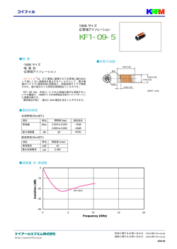
Product Specification
製品規格
108-78519
02DEC2008 Rev. A
ファンモーターコネクタ (タ
(ダイナミック D1000 Series)
FAN MOTOR CONNECTOR (Dynamic D1000 Series)
Series)
1. 適用範囲
1.1 内容
本規格は、ファンモーターコネクタの製品性能、
試験方法、品質保証の必要条件を規定している。
適用製品名と型番は附表1の通りである。
1 Scope :
1.1 Contents
This specification covers the requirements for product
performance, test methods and quality assurance
provisions of Fan Motor connector.
Applicable product description and part numbers are as
shown in Appendix 1.
2.
参考規格類
以下規格類は本規格中で規定する範囲内に於いて、本
規格の一部を構成する。万一本規格と製品図面の間に不
一致が生じた時は、製品図面を優先して適用すること。万
一本規格と参考規格類の間に不一致が生じた時は、本規
格を優先して適用すること。
2. Applicable Documents:
The following documents form a part of this specification to
the extent specified herein. In the event of conflict
between the requirements of this specification and the
product drawing, the product drawing shall take
precedence.
In the event of conflict between the
requirements of this specification and the referenced
documents, this specification shall take precedence.
2.1 AMP 規格
A. 109-5000 :
B. 501-5635 :
501-5976 :
C. 114-5377 :
D. 411-78325 :
2.1 AMP Specifications :
A. 109-5000 Test Specification, General
Requirements for Test Methods
B. 501-5635
TEST REPORT
501-5976
C. 114-5377
Apprication Specification
D. 411-78325 Instruction Sheet
試験法の一般条件
性能試験評価報告書
取付適用規格
取扱説明書
2.2 民間団体規格
A. MIL-STD-202 :
B. IEC.512
:
電子電気部品の試験方法
試験法規格
2.1 Commercial Standards and Specifications :
A. MIL-STD-202
B. IEC 512 Test Specification
タイコ エレクトロニクス アンプ株式会社 (〒213-8535 川崎市高津区久本 3-5-8)
Tyco Electronics AMP K.K. (3-5-8 Hisamoto Takatsu-ku Kawasaki, 213-8535)
© Copyright 2007 Tyco Electronics AMP K.K. All international rights reserved.
* : 商標 Trademark
1 of 13
Product Specification
108-78519
3. 一般必要条件
3.1 設計と構造
製品は該当製品図面に規定された設計、構造、物理的寸法を
もって製造されていること。
3. Requirements :
3.1 Design and Construction :
Product shall be of the design, construction and physical
dimensions specified on the applicable product drawing.
3.2 材 料
3.2
A.
コンタクト
材質:銅合金
表面処理:全面ニッケル下地メッキ
接触部:金メッキ
A. Contact
Material : Copper Alloy
Finish : Nickel plating all over
Contact Point : Gold plating
B.
ハウジング
材質:ガラス入りポリエステル樹脂
色:黒
難燃性:UL94V-0
C.
その他
シールリング:材質:シリコン
ラバープラグ:材質:シリコン
キャップパッキン:シリコン
3.3
A.
B.
C.
定 格
定格電圧 : 250 V AC/DC
定格電流
Fig.1 参照
使用温度範囲 -30℃~105℃
(但し、温度の上限には、負荷電流によっ
て生じる温度上昇分を含む)
D. 微小定格
1 mV, 1 μA 以上
E. 適用電線範囲(ラバープラグ)
ラバープラグ
316867-1
967067-1
967067-2
Materials
B.
Housing
Material : G.F.Polyester
Color : Black
Flammability : UL 94V-0
C.
Other
Seal Ring :Material : Silicon
Rubber Plug :Material : Silicon
Cap packing :Material : Silicon
3.3 Ratings :
A. Voltage Rating : 250 V AC/DC
B. Current Rating : See Fig. 1
C. Temperature Rating : -30℃ to 105℃
(Include temperature rising by
energized current)
D. Minimum Ratin1g : 1mV, 1μA Minimum
E. Application Wire(Rubber Plug)
Rubber Plug
316867-1
967067-1
967067-2
絶縁被覆外径(mm)
Φ1.4~Φ1.7
Φ1.4~Φ2.1
Φ0.9~Φ1.4
Insulation Diameter(mm)
Φ1.4~Φ1.7
Φ1.4~Φ2.1
Φ0.9~Φ1.4
Current Rating
単位
Unit : A
電線サイズ
Wire Size
AWG
#18
AWG
#20
AWG
#22
AWG
#24
AWG
#26
AWG
#28
AWG
#30
5
4
3
2.5
2
1.5
1
極数
Pos.
3Pos.
Fig. 1
3.4 性能必要条件と試験方法
製品は Fig.2 に規定された電気的、機械的、及び耐環境的
性能必要条件に合致するよう設計されていること。試験は特
別に規定されない限り室温下で行われること。
Rev. A
3.4 Performance Requirements and Test Descriptions :
The product shall be designed to meet the electrical,
mechanical and environmental performance requirements
specified in Fig.2. All tests shall be performed in the
room temperature unless otherwise specified.
2 of 13
Product Specification
3.5
性能必要条件と試験方法の要約
項番
No.
試験項目
Test Items
規格値
Requirements
試験方法
Procedures
項番
No.
試験項目
Test Items
規格値
Requirements
試験方法
Procedures
項番
No.
試験項目
Test Items
規格値
Requirements
試験方法
Procedures
3.5
108-78519
Test Requirements and Procedures Summary :
3.5.1
製品の確認
Examination of Product
製品図面と AMP 取付適用規格
Meets requirements of product drawing and
114-5377 の必要条件に合致していること。各 AMP Specification (114-5377)
試験後は、性能に影響する様な腐蝕なきこ After test, no corrosion influence performance.
と。
目視により、コネクタの機能上支障をきたす Visual inspection
損傷を検査する。
No physical damage
電 気 的 性 能 Electrical Requirements
3.5.2
総合抵抗(ローレベル)
Termination Resistance (Low Level)
10 mΩ 以下 (初期)
20 mΩ 以下 (終期)
ハウジングに組み込まれ嵌合したコンタクト
を開路電圧 20mV 以下、閉路電流 10mA 以
下の条件で測定する。
但し、電線の抵抗分は差し引く。
Fig. 6 参照。
AMP 規格 109-5311-1
10 mΩ Max. (Initial)
20 mΩ Max. (Final)
Subject mated contacts assembled in housing to
20mV Max. open circuit at 10mA. Take the
resistance of the wire only away from
measurement
Fig. 6.
AMP Spec. 109-5311-1
3.5.3
絶縁抵抗
Insulation Resistance
1000 MΩ 以上 (初期)
100 MΩ 以上 (終期)
500 V DC 印加。
コネクタ嵌合した状態で隣接コンタクト間の
間で測定。
MIL-STD-202, 試験法 302 条件 B
AMP 規格 109-5302
1000 MΩ Min. (Initial)
100 MΩ Min. (Final)
Impressed voltage 500 V DC.
Test between adjacent circuits
mated connectors.
AMP Spec. 109-5302
MIL-STD-202, Method 302
Condition B
contact of
Fig. 2 (続く) (To be Continued)
Rev. A
3 of 13
Product Specification
項番
No.
試験項目
Test Items
規格値
Requirements
試験方法
Procedures
項番
No.
試験項目
Test Items
規格値
Requirements
試験方法
Procedures
3.5.4
耐電圧
Dielectric withstanding Voltage
沿面放電、フラッシュオーバー等がないこと。
(初期及び終期)
リーク電流 0.5 mA 以下
コネクタ嵌合した状態で隣接コンタクト間で
測定。
1 分間印加測定。
1.5KV AC
No creeping discharge nor flashover shall occur.
Current leakage : 0.5 mA Max.
試験方法
Procedures
1.5KV AC for 1 minute.
Test between adjacent circuits contact of mated
connectors.
3.5.5
温度上昇
Temperature Rising
規定電流を通電して、温度上昇は 30℃ 以
下
通電による温度上昇を測定すること。測定
は、空気の対流の影響を受けない条件で測
定する。ハウジングには、全極にコンタクトを
装着し通電する。熱電対は端子の芯線圧着
部に付けて測定する。
Fig. 1 参照
AMP 規格 109-5310
30℃ Max. under loaded specified current.
機 械 的 性 能
項番
No.
試験項目
Test Items
規格値
Requirements
108-78519
Measure temperature rising by energized
current.
Subject measurement must do at the place of no
influence from convection of air. And contacts
assembled in housing all of circuits.
The thermocouple attach to crimp of the wire
barrel of contact.
Fig. 1
AMP Spec. 109-5310
Mechanical Requirements
3.5.6
振動(高周波)
Vibration (High Frequency)
振動中 1 μsec. をこえる不連続導通を生
じないこと。
20mΩ以下 (終期)
嵌 合 し た コ ネ ク タ に 1.52mm の 振 幅 で 、
10-500-10Hz に毎分 1 サイクルの割合で変
化する掃引振動を直交する三方向軸に各 3
時間ずつ与えること。
100 mA を通電。
AMP 規格 109-5201
MIL-STD-202, 試験法 201A
No electrical discontinuity greater than 1 μ
sec. shall occur.
20 mΩ Max. (Final)
Subject mated connectors to 10-500-10 Hz
traversed in 1 minute at 1.52mm amplitude 3
hours each of 3 mutually perpendicular planes.
100 mA applied.
AMP Spec. 109-5201
MIL-STD-202, Method 201A
Fig. 2 (続く) (To be Continued)
Rev. A
4 of 13
Product Specification
項番
No.
試験項目
Test Items
規格値
Requirements
試験方法
Procedures
3.5.7
衝撃
Shock
衝撃により 1μ sec. をこえる不連続導通を
生じないこと。
20 mΩ 以下 (終期)
嵌合したコネクタ
加速度 : 490m/s2
衝撃パルス波型
:正弦波形
持続時間 :
11 m sec.
衝撃回数 :
X, Y, Z 軸正逆方向に
各 3 回宛、 合計 18 回
AMP 規格 109-5208
MIL-STD-202, 試験法 213
項番
No.
試験項目
Test Items
規格値
Requirements
試験方法
Procedures
項番
No.
試験項目
Test Items
規格値
Requirements
試験方法
Procedures
108-78519
条件 A
No electrical discontinuity greater than
1μ sec. shall occur.
20 mΩ Max. (Final)
Mated connectors
Accelerated Velocity : 490m/s2
Waveform
: Sign Curve
Duration
: 11 m sec.
Number of Drops : 3 drops each to normal
and reversed directions of X, Y and Z axes,
totally 18 drops
AMP Spec. 109-5208
MIL-STD-202, Method 213 Condition A
3.5.8
コネクタ挿抜力
Connector Mating/Unmating Force
挿入力
58.8N(6kg) 以下
Mating
Force
引抜力
39N(4kg) 以下
Unmating 39N Max.
Force
(4kg) Max.
Operation Speed : 25 mm/min.
Measure the force required to mate/unmate
connectors.
Measure the Mating Force required to make
connector with the locking of housing.
Measure the Unmating Force required to make
connector without the locking of housing.
ハウジングにコンタクトを組込み操作速度
25mm/分で挿入引抜に要する力を測定。
挿入力測定時、ハウジングのロック機構は、
作用させておく。
引抜力測定時、ハウジングのロック機構は取
り除いておく。
58.8N Max.
(6kg) Max.
3.5.9
コンタクト装着力
Contact Insertion Force
7.84N (0.8kgf) 以下
1 コンタクト当たり
コンタクトをハウジングに装着するのに要す
る力を測定すること。
AMP 規格 109-5211
7.84N (0.8 kgf) Max. per contact
Measure the force required to insert contact
into housing.
AMP Spec. 109-5211
Fig. 2 (続く) (To be Continued)
Rev. A
5 of 13
Product Specification
項番
No.
試験項目
Test Items
規格値
Requirements
試験方法
Procedures
項番
No.
試験項目
Test Items
規格値
Requirements
3.5.10
コンタクト保持力
Contact Retention Force
14.7N (1.5 kgf) 以上
14.7N(1.5kgf) Min.
電線に圧着したコンタクトをハウジングに組 Apply an axial pull-off load to crimped wire.
込み、電線を軸方向に 100mm/分で引張り、 Operation Speed : 100 mm / min.
抜ける時の荷重を測定すること。
AMP Spec. 109-5210
3.5.11
コンタクト挿入引抜力
Contact Mate/Unmating Force
挿入力
Mate
2.94N(300g) 以下(初回~50 回)
引抜力
試験方法
Procedures
項番
No.
試験項目
Test Items
規格値
Requirements
試験方法
Procedures
項番
No.
試験項目
Test Items
規格値
Requirements
試験方法
Procedures
108-78519
0.12N(12g)以上(初回)
0.08N (8g)以上(50 回)
毎分 100 mm の速度で測定
AMP 規格 109-5206
圧着部引張強度
mm2
2.94N(300g)Max.(1st~50th)
Unmating
0.12N(12g)Min. (1st)
0.08N (8g)Min. (50th)
Operation speed 100 mm/min
AMP Spec. 109-5206
3.5.12
Crimp Tensile Strength
電線サイズ
引張強度 (以上)
(AWG)
N (kgf)
0.05
30
4.9(0.5)
0.08
28
9.8(1)
0.14
26
19.6(2)
0.22
24
29.4 (3)
0.34
22
44.1 (4.5)
0.5
20
63.7 (6.5)
0.75
18
63.7 (6.5)
圧着したコンタクトを試験機に固定し、軸方
向引張力を電線に加える。尚、インスレーショ
ンバレル部は取り除き、圧着電線(電線
75mm)の端部をはんだ付けしておき、はんだ
付け部を固定して引張る。
操作速度は 100mm/分
AMP 規格 109-5205
mm2
Wire Size
Crimp Tensil (min.)
(AWG)
N (kgf)
0.05
30
4.9(0.5)
0.08
28
9.8(1)
0.14
26
19.6(2)
0.22
24
29.4 (3)
0.34
22
44.1 (4.5)
0.5
20
63.7 (6.5)
0.75
18
63.7 (6.5)
Apply an axial pull-off load to crimped wire of
contact secured on the tester,
Operation Speed : 100 mm/min.
Subject take insulation barrel away.
AMP Spec. 109-5205
3.5.13
耐久性 (繰り返し挿抜)
Durability (Repeated Mate/Unmating)
20mΩ以下
20 mΩ Max
挿抜回数 50 回
No. of Cycles : 50 cycles
Fig. 2 (続く) (To be Continued)
Rev. A
6 of 13
Product Specification
項番
No.
試験項目
Test Items
規格値
Requirements
試験方法
Procedures
項番
No.
試験項目
Test Items
規格値
Requirements
試験方法
Procedures
項番
No.
試験項目
Test Items
規格値
Requirements
試験方法
Procedures
108-78519
3.5.14
ハウジング ・ ロック強度
Housing Locking Strength
24.5N (2.5 kgf) 以上
24.5 N (2.5 kgf) Min.
コネクタのロック強度を操作速度 100 mm/ Measure connector locking strength.
分で測定
Operation Speed : 100 mm/min.
AMP 規格 109-5210
AMP Spec. 109-5210
3.5.15
熱衝撃
Thermal Shock
20 mΩ 以下 (終期)
20 mΩ Max. (Final)
嵌合したコネクタにて
-55℃/30 分、 85℃/30 分
これを 1 サイクルとし 25 サイクル行う。
AMP 規格 109-5103 条件 A
MIL-STD-202 試験法 107-1 条件 A-1
但し、測定は室内放置 3 時間後行う。
Mated connector
-55℃/30 min., 85℃/30 min.
Making this a cycle, repeat 25 cycles.
AMP Spec. 109-5103 Condition A
MIL-STD-202 Method 107-1
Condition A-1
The measurement is held after being left indoor
for 3 hours.
3.5.16
温湿度サイクリング
Humidity-Temperature Cycling
耐電圧 1 分間 (終期)
1.5KV AC
リーク電流 0.5 mA 以下
絶縁抵抗 100 MΩ 以上 (終期)
総合抵抗 20 mΩ 以下 (終期)
嵌合したコネクタを 25~65℃,
80~95 % R. H と-10℃
寒冷衝撃を 10 サイクル実施する
AMP 規格 109-5106
MIL-STD-202, 試験法 106
但し、測定は室内放置 3 時間後行う。
1 サイクル:24 時間。
Dielectric withstanding voltage 1 minute.
1.5KV AC
Current leakage : 0.5 mA Max.
Insulation resistance 100 MΩ Min. (Final)
Termination resistance 20 mΩ Max. (Final)
Mated connector, 25~65℃,
80~98 % R. H. 10 cycles
Cold shock -10℃(not ) performed
AMP Spec. 109-5106
MIL-STD-202, Method 106
The measurement is held after being left indoor
for 3 hours. 1cycle=24hours
Fig. 2 (続く) (To be Continued)
Rev. A
7 of 13
Product Specification
項番
No.
試験項目
Test Items
規格値
Requirements
試験方法
Procedures
項番
No.
試験項目
Test Items
規格値
Requirements
試験方法
Procedures
項番
No.
試験項目
Test Items
規格値
Requirements
試験方法
Procedures
項番
No.
試験項目
Test Items
規格値
Requirements
試験方法
Procedures
108-78519
環 境 的 性 能 Environmental Requirements
3.5.17
塩水噴霧
Salt Spray
20 mΩ 以下 (終期)
20 mΩ Max. (Final)
性能に影響する様な腐食なきこと。
No corrosion influence performance
嵌合したコネクタを 5±1%の塩水噴霧に 48 Subject mated connectors to 5±1% salt
時間さらすこと。
concentration for 48 hours :
MIL-STD-202, 試験法 101
条件 B
MIL-STD-202, Method 101 Condition B
測定は塩の堆積物を水洗した後、常温で自 The measurement is held after remove the salt
然乾燥後行う。
and dry up at indoor.
3.5.18
高温寿命
Temperature Life (Heat Aging)
20 mΩ 以下 (終期)
20 mΩ Max. (Final)
嵌合したコネクタを 105±2℃
期間 96 時間さらすこと。
AMP 規格 109-5104-3 条件 A
但し、測定は室内放置 3 時間後に行うこと。
Mated Conn. 105±2℃
Duration :96 hr
AMP Spec. 109-5104-3 Condition A
The Measurement is held after being left indoor
for 3 hours.
3.5.19
工業ガス(SO2)
SO2 Gas
20 mΩ 以下 (終期)
性能に影響する様な腐食なきこと。
嵌合したコネクタ
SO2 ガス 10ppm 95%RH
25℃ 96 時間
AMP 規格 109-5107 条件 C
20 mΩ Max. (Final)
No corrosion influence performance
Mated conn.
SO2 Gas : 10ppm. 95%RH
25℃, 96hours
AMP Spec. 109-5107 Condition C
3.5.20
散水試験
Water Sprinkle
リーク電流は、100μA 以下のこと。
Current leakage:100μA Max
コネクタを散水試験槽内に吊るし、30 分間
常温水を散水する。散水条件は、JISD0203
の S1 とする。試験中はコネクタの各極間に
24VDC の電圧を印加しリーク電流を記録す
る。なお試験を実施するときは、
リードワイヤは 2m とし、試験槽の外へ出す。
Suspend mated connector in a closed chamber.
Subject it followed by sprinkling of water at room
temperature for 10 minutes.per.JIS D 0203.R1.
Energize the contacts with 24V DC,amd monitor the
circuits for current leakage.
Connected 2-meter lead wires are drawn out of the
chamber for measurement.
Fig. 2(終り) (End
*
製品外観 : 製品は錆、腐食、変形、割れ、カケ、
変色等の異常なきこと。
Rev. A
Product must be without rust, corrosion
transformation, crack and discoloration.
8 of 13
Product Specification
3.6 製品認定試験の試験順序
試 験 項 目
製品の確認検査
総合抵抗 (ローレベル)
耐電圧
絶縁抵抗
温度上昇
振動
衝撃
コネクタ挿入力
コネクタ引抜力
コンタクト装着力
コンタクト挿入力
コンタクト引抜力
圧着部引張強度
耐久性 (繰り返し挿抜)
ハウジングロック強度
温湿度サイクリング
熱衝撃
塩水噴霧
コンタクト保持力
(1)
(2)
3
Confirmation of
Product
Termination Resistance
(Low Level)
Dielectric withstanding
Voltage
Insulation
Resistance
Temperature
Rising
Vibration
(Low Frequency)
Physical
Shock
Connector Mating
Force
Connector Unmating
Force
Contact Insertion
Force
Contact Mating
Force
Contact Unmating
Force
Crimp Tensile
strength
Durability
(Repeated Mating/Unmating)
Housing Locking
Strength
Humidity-Temperature
Cycling
Thermal
Shock
Salt Spray
1,3
1,4
1,3
高温寿命
工業ガス(SO2)
散水試験
Water Sprinkle
Rev. A
3.6 Product Qualification Test Sequence
Test or Examination
Contact Retention
Force
Temperature Life(Heat Asing)
SO2
108-78519
試験グループ
Test Group
4
(5)
6
試 験 順 序
Test Sequence (a)
1,3
1,3
1,4
7
8
(9)
1,7
1,9
1,4
2,4,
6
2,8
2,5
3
2
2
3
5
3,6
4,7
2
2
3
2
5
2
3
5
9 of 13
Product Specification
108-78519
Test or Examination
(10)
(11)
1,4
1,4
2,5
2,5
2,5
高温寿命
工業ガス(SO2)
Confirmation of
Product
Termination Resistance
(Low Level)
Dielectric withstanding
Voltage
Insulation
Resistance
Temperature
Rising
Vibration
(Low Frequency)
Physical Shock
Connector Mating
Force
Connector Unmating
Force
Contact Insertion
Force
Contact Mating
Force
Contact Unmating
Force
Crimp Tensile
strength
Durability
(Repeated Mating/Unmating)
Housing Locking
Strength
Humidity-Temperature
Cycling
Thermal Shock
Salt Spray
Contact Retention
Force
TemperatureLife(Heat Asing)
SO2
試験グループ
Test Group
(12) (13) 14
試 験 順 序
Test Sequence (a)
1,4 1,4 1,3
散水試験
Water Sprinkle
試 験 項 目
製品の確認検査
総合抵抗 (ローレベル)
耐電圧
絶縁抵抗
温度上昇
振動 (低周波)
衝撃
コネクタ挿入力
コネクタ引抜力
コンタクト装着力
コンタクト挿入力
コンタクト引抜力
圧着部引張強度
耐久性 (繰り返し挿抜)
ハウジングロック強度
温湿度サイクリング
熱衝撃
塩水噴霧
コンタクト保持力
2,5
7
6
3
3
3
3
2
Fig.3(2/2)
Rev. A
10 of 13
Product Specification
108-78519
4.
品質保証条件
4.1
試験条件
特に指定のない場合、下記に示す環境条件のもとで性能試
験を行うものとする。
4.
Quality Assurance Provisions :
4.1
Test Conditions :
Unless otherwise specified, all the test shall be performed
in any combination of the following test conditions.
温 度
相対湿度
気 圧
Temperature :
Relative Humidity :
Atmospheric Pressure :
15~35℃
45~75 %
86.6~106.6 Kpa
15~35℃
45~75 %
86.6~106.6 Kpa
Fig. 4
4.2
試験
4.2.1
試料
性能試験に用いる試料は、該当製品図面上の規定事項に
合致したものであること。また圧着コンタクトは『ダイナミックコ
ネクタ D1000 シリーズ・コンタクトの圧着条件 114-5377』に
基づいて Fig. 5 に示す電線を圧着した正規の試料である
こと。
4.2
Tests :
4.2.1
Test Specimens :
The test specimens to be employed for the tests shall be
conforming to the requirements specified in the applicable
product drawings. The crimped contacts shall be prepared
in accordance with the requirements of applicable
application Specification, 114-5377, Crimping of DYNAMIC
CONNECTOR D1000 Series. on the wires specified in Fig.
5 of this specification.
4.2.2
使用電線
4.2.2
Applicable Wires :
性能試験して用いる電線は、Fig. 5 に示す電線にて行うも The wires to be used for crimping the samples for
のとする。
performance testing shall be conforming to the
requirements specified in Fig. 5.
計算断面積(mm2)
Calculated
Cross-sectional
Area(mm2)
0.05
0.08
0.14
0.22
0.34
0.50
0.85
AWG
素線径(mm)
Diameter of a
Conductor (mm)
素線数
Number of
Conductors
絶縁被覆外径(mm)
Insulation Outer
Diameter (mm)
30
28
26
24
22
20
18
0.102
0.12
0.16
0.16
0.16
0.16
0.16
7
7
7
11
17
26
43
0.8
1.08
1.3
1.4
1.6
1.8
2.1
Fig. 5
Rev. A
11 of 13
Product Specification
108-78519
mΩ=(V―Vw1-Vw2)/A
*
測定値から電線抵抗値を引くこと。
*
Take the resistance of wire only away
Fig. 6 総合抵抗 (ローレベル)、温度上昇
Fig. 6 Termination Resistance (Low Level) and Temperature Rising Vs. Current Measuring Methods
Rev. A
12 of 13
Product Specification
製品名
Description
DYNAMIC D1000
Receptacle Contact S-type
DYNAMIC D1000
Receptacle Contact M-type
DYNAMIC D1000
Receptacle Contact L-type
DYNAMIC D1000
Receptacle Contact 2L-type
DYNAMIC D1000
Tab Contact S-type
DYNAMIC D1000
Tab Contact M-type
DYNAMIC D1000
Tab Contact L-type
型 番
Part No.
1827569-2 (REEL)
1827586-2 (L/P)
1827570-2 (REEL)
1827587-2 (L/P)
1827571-2 (REEL)
1827588-2 (L/P)
1827572-2 (REEL)
1827589-2 (L/P)
1903111-2 (REEL)
1903115-2 (L/P)
1903112-2 (REEL)
1903116-2 (L/P)
1903113-2 (REEL)
1903117-2 (L/P)
Tab Contact 2L-type
1903114-2 (REEL)
1903118-2 (L/P)
.060 Rubber Plug
316867-1
MQS,Wire Seal
967067-1
MQS,Wire Seal
967067-2
DYNAMIC D1000
108-78519
PLUG HSG 3P Assembly
2013891-1
CAP HSG 3P Assembly
2013892-1
附表 1
Appendix 1
Rev. A
13 of 13
© Copyright 2026 Paperzz