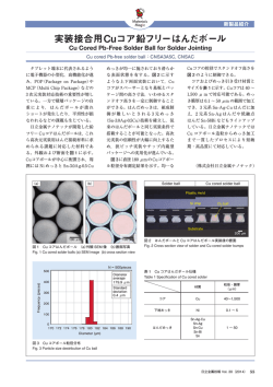
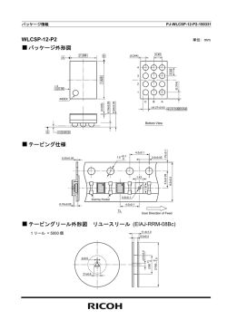
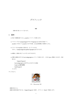
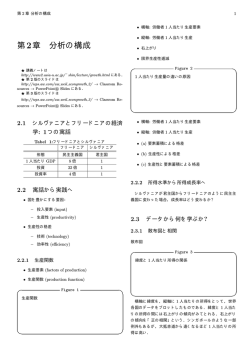
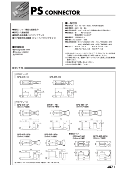
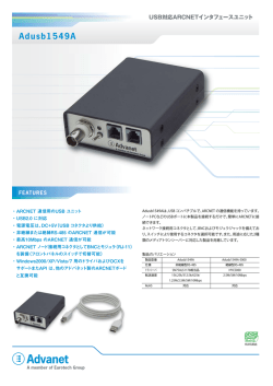
Instruction Product Specification
製品取り付け規格
114-5503
28Nov14 Rev D
Metal-Shell Micro Circular Connector
本規格中の全ての数値はメートル表記です。 又全ての寸法表記も特に規定がない限りメートル表記です。 特に規定
がない限り原則、寸法は ±0.1 の公差を含みます。 角度は±2度の公差を含みます。 本規格書中のイラストは厳密
スケールでは描かれておりません。 確認用資料に止めてください。
All numerical values are in metric units Dimensions are in millimters. Unless otherwise specified,
dimensions have a tolerance of ±0.1 and angles havea tolerance of ±2 Figures and illustrations are for
identification only and are not drawn to scale.
1. イントロダクション
本規格は、Metal–Shell Micro Circular Connector (ピン・ソケットコンタクト及びスプリングプロブ-コンタクト)の取付
け必要条件について規定しています。 本製品は、主に耐久性と信頼性が重視される産業、一般商用、軍事用に使用
されます。
防水規格は(IP67)クラスでシールド機能付コネクタとしてワイヤとワイヤ、ワイヤとボード、の嵌合に適し、ナットによる
パネル取り付けも可能です。
コンタクト構成は7ピン(シェルサイズ M11)、19ピン(シェルサイズ M14)、14ピン(シェルサイズ M15)、30ピン(シェル
サイズ M22)のプラグ、リセにて構成されています。 また 14ピン、30ピンにおいては、それぞれ信号系、パワー系の混
合コンタクト構成となります。 -Figure 1 参照コンタクトの結線方法はソルダーカップ方式とソルダーテイル方式の2種類あり、プラグとレセのソルダーカップには、
下記のケーブルサイズが接続可能です。
・ 7ピン, 19ピン : 24 ~ 30AWG (24AWGは、7本撚りまでとする)
・ 14 ピン : 信号系=24AWG (19 ストランド)
パワー系=20AWG (19 ストランド)
・ 30 ピン : 信号系=24AWG (19 ストランド)
パワー系=22AWG (19 ストランド)
コンタクト嵌合方式はスプリングプローブ&パット及びピン&ソケットの2方式で、結線組立に特別な工具を必要としま
せん。
必要に応じて追加オプション部品の選定も可能です。 -Figure 2 参照当社との連絡には当規格書文中にある部品名称にてお問合せ下さい。 当製品に係る基本的名称、用語に関しては
Figure 1 に規定しております。
1. INTRODUCTION
This specification covers the requirements for application of Metal–Shell Micro Circular Connectors with Pin
and Socket or Spring Probe Contacts. This system is used primarily in industrial, commercial and military
applications where durability and reliability are of primary concern. This environmentally sealed (IP67) and
Shielded Connector system is available as Cable–to–Cable, Cable–to–Board, in Nut style rear Panel–mount
configuration.
Shell size M11 accommodates 7 contacts maximum, Shell size M14 accommodates 19 contacts maximum,
Shell size M15 accommodates 14 contacts maximum, Shell size M22 accommodates 30 contacts maximum.
The configuration of 14&30 contacts is a hybrid of Signal and Power Contacts. See Figure 1.
Plugs incorporate Solder Cup terminals which will accommodate as below.
・7&19 contacts: AWG 24 to 30 (24 AWG is limited to 7 strands).
・14 contacts: Signal=AWG24(19 strands)
Power=AWG20(19 strands)
・30 contacts: Signal=AWG24(19 strands)
Power=AWG22(19 strands)
©2012 Tyco Electronics Japan G.K.,
a TE Connectivity Ltd. Company
All Rights Reserved
TE logo is a trademark.
* Trademark
タイコエレクトロニクス ジャパン合同会社、TE Connectivity Ltd. グループ
Other products, logos, and company names might be trademarks of their respective owners.
1 of 24
LOC B
Instruction Product Specification
製品取り付け規格
114-5503
And are available in Pin and Socket or Spring Probe to Pad interface. No assembly or application tooling is
required to terminate or assemble these connectors. Optional ancillary items are also available for your
application requirements. See Figure 2.
When corresponding with Tyco Electronics Personnel, use the terminology provided in this specification to
facilitate your inquiries for information. Basic terms and features of this product are provided in Figure 1.
Polarity Feature
(Colored area)
カップリング カラー エリア
Coupling Lock Ring
カップリング ロックリング
Polarity Feature
(Color Key)
カップリング カラー キー
Socket Contact
ソケット コンタクト
Pin Contact
ピン コンタクト
Solder tail Contact
ソルダーテイル コンタクト
Solder Cup Contact
ソルダーカップ コンタクト
Adapter
アダプター
Nut
ナット
Wave Washer
ウェーブ ワッシャー
19-Position Plug
Connector
(Thread)
19ピン プラグ コネクタ
(スレッド)
19-Position Receptacle
Connector
(Thread)
19ピン リセ コネクタ
(スレッド)
Constitution of connector / コネクタの構成
Figure 1
Dust Cap Receptacle
(Thread)
ダスト キャップ リセ
(スレッド)
Dust Cap Plug
(Bayonet)
ダスト キャップ プラグ
(バイオネット)
Clamping Band-Straight
ステンレス バンド
Accessories for New Metal-Shell Micro Circular Connectors / アクセサリー オプション
Figure 2
Rev D
2 of 24
Instruction Product Specification
製品取り付け規格
114-5503
2. 関連事項
2. REFERENCE MATERIAL
2.1. 改版履歴
・Rev C. 2013年9月12日
7ピン アダプタ-取り付けトルク値追加
・Rev D. 2014年11月28日 19, 14, 30ピン アダプタ-取り付けトルク値追加
誤記修正 Fig 18, Fig 24
2.1. Revision Summary
・Rev C. 12SEP2013
Added the recommended installation torque value of 7 contacts Adaptor.
・Rev D. 28NOV2014
Added the recommended installation torque value of 19, 14 and 30 contacts
Adaptor.
Correction of errors. Fig 18, Fig 24
2.2. 顧客支援
本規格書にて使用している製品番号は、Metal–Shell Micro Circular Connector の製品番号であり、製品コード
K341はMetal–Shell Micro Circular Connector の製品コードです。 当社のホームページにて製品情報の問い合わ
せをする際や取付け工具の情報を得る際の参考にして下さい。 お近くの当社支店、または、購入後の問い合わせ
に関しては本ページの最後に記載した当社製品インフォメーション センターへご確認下さい。
2.2. Customer Assistance
Reference Base Product Part Numbers and Product Code K341 are representative of Metal–Shell Micro
Circular Connectors. Use of these numbers will identify the product line and expedite your inquiries through
a service network established to help you obtain product and tooling information. Such information can be
obtained through a local Tyco Electronics Representative or, after purchase, by calling Product Information
at the number at the bottom of page.
2.3
2.3. 図面
個々の製品番号に該当する顧客図面は当社のホームページより取得頂けます。 もし当規格書と取得した顧客図面
あるいは取得した技術資料と情報の相違がある場合は前項でご案内した当社製品インフォメーション センターまでお
問合せ下さい。
2.3. Drawings
Customer Drawings for product part numbers are available from the service network. If there is a conflict
between the information contained in the Customer Drawings and this specification or with any other
technical documentation supplied, call Product Information at the number at the bottom of para 2.2.
2.4.
2.4. 関連作業手順書
ハンダ付けに関する作業手順書、文書番号 402-40 が当社ホームページから取得頂けます。 当手順書にて各種フ
ラックスの特性や種別、除去方法に関しての情報が得られます。 又、ハンダ付け作業の際の不具合チェックリストも
掲載しております。
2.4. Manuals
Manual 402–40 is available upon request and can be used as a guide in soldering. This manual provides
information on various Flux types and characteristics along with commercial designations and flux removal
procedures. A checklist is included in the manual as a guide for information on soldering problems.
Rev D
3 of 24
Instruction Product Specification
製品取り付け規格
114-5503
2.5
2.5. 製品規格及び参考仕様
IPC/EIA S–STD–001 (電気半田及び組立に関する規格)に高品質な配線、結線をするための材質、方法、仕上りの
記述があります。
IPC/WHMA–A–620 (ケーブル及びワイヤーハーネス組立に関する規格)にカシメ仕上がり基準、機械的確実性、半
田結線の記述があります。
2.5. Standards and Publications
IPC/EIA S–STD–001 (Requirements for Soldered Electrical and Electronic Assemblies) describes materials,
methods, and verification criteria for producing high quality soldered interconnections. IPC/WHMA–A–620
(Requirements and Acceptance for Cable and Wire Harness Assemblies) describes acceptability criteria for
crimped, mechanically secured and soldered interconnections.
2.6.
2.6. 製品仕様
当社製品仕様書108–78938, 108-78967 に Metal–Shell Micro Circular Connector の製品性能及びテスト規格の
記述があります。
また、テストレポート 501-78493, 501-78526 に New Metal–Shell Micro Circular Connector の製品確認テストの
条件、方法、評価結果の記述があります。
2.6. Specifications
Product Specification 108-78938, 108-78967provides product performance and test information for New
Metal–Shell Micro Circular Connectors. And Test Report 501-78493, 501-78526 provides product
performance and test information for the Spring Probe to Pad Contacts, and Pin to Socket Contacts.
3. 必要条件
3. REQUIREMENTS
3.1.
3.1. 安全確認
製品輸送梱包が変形するダメージを受けるほどに製品を必要以上に積上げないで下さい。
3.1. Safety
Do not stack product shipping containers so high that the containers buckle or deform.
3.2. 製品保管
A. 紫外線
長期間の紫外線曝露は製品素材に使用されている化学構成品の劣化を招く原因になります。
B. 保存
製品を使用する直前まで製品梱包内にて保管してください。 製品性能を劣化させる保存中の塵埃の影響を少な
くするためにコネクタの使用は先入れ先出しを基本に使用してください。
C. 化学品環境
コンタクトの腐食やクラックの原因となるため、製品を下記にあげる化学薬品の影響を受ける環境にて保存しない
で下さい。
アルカリ
アミン
Rev D
アンモニア
炭酸塩
クエン酸塩
隣酸塩クエン酸塩
硫黄化合物
亜硝酸塩
硫黄亜硝酸塩
酒石塩酸
4 of 24
Instruction Product Specification
製品取り付け規格
114-5503
3.2. Storage
A. Ultraviolet Light
Prolonged exposure to ultraviolet light may deteriorate the chemical composition used in component
material.
B. Shelf Life
Components should remain in the shipping containers until ready for use. The connectors should be used
on a first in, first out basis to avoid storage contamination that could adversely affect performance.
C. Chemical Exposure
Do not store connectors near any chemical listed below as they may cause stress corrosion cracking in
the contacts.
Alkalies
Amines
Ammonia
Citrates
Carbonates Nitrites
Phosphates Citrates Sulfur Compounds
Sulfur Nitrites
Tartrates
3.3. 材質
当コネクタの構成部品は下記材質より製造されています。
・
・
・
・
・
・
・
スプリングプロ-ブピン : 黄銅 ニッケル下地メッキ 金メッキ仕上げ.
スプリングプロ-ブピンコンタクト : 黄銅 ニッケル下地メッキ 金メッキ仕上げ.
ソケットコンタクト : 黄銅 ニッケル下地、金メッキ仕上げ .
ピンコンタクト : 黄銅 ニッケル下地、 金メッキ仕上げ.
コネクタシェル : 黄銅 ニッケル下地メッキ、ブラック錫ニッケルメッキ.
インシュレーター : 耐熱サーモプラスティック.
O-リング : フッ素系シリコンラバー.
3.3. Materials
The connector components are made from the following materials:
・
・
・
・
・
・
Spring Probe Pin: Brass with gold finish over nickel on entire contact.
Spring Probe Pad and Pin Contact: Brass with gold finish over nickel on entire contact.
Socket Contact: Brass with gold finish over nickel on entire contact.
Connector Shell: Black Sn-Ni over nickel.
Insulator: High temperature white thermoplastic.
Rings: Fluor silicone.
3.4. 使用温度条件
-55 ~ +150 ℃
3.4. Ambient temperature
-55 ~ +150 ℃
Rev D
5 of 24
Instruction Product Specification
製品取り付け規格
114-5503
3.5. アダプタ
下記 Figure 3 は当コネクタに取り付ける推奨製品です。
3.5. Adapters
The following table in Figure 3 provides information on the usage of various adapters.
シールドアダプタ X モールドブーツ 収縮チューブ
Overmold or Shrink tube with or without Shield termination brass adapter
Figure 3
3.6. ケーブルの選定 及び準備
A. ケーブルの選定
2
適用ケーブルサイズは0.06 – 0.2 mm (30 - 24 AWG)です。 まず必要な長さにカットしてください。
ケーブル外径はプラグコネクタに接続するアダプタのサイズ内で決定してください。
(ケーブル外形に合わせたアダプタを選定下さい) -パラグラフ 3.5. Figure 3 参照24 AWG はソリッド線又は7本ストランドまでが適用サイズです。
B. ケーブルの準備
1. ケーブルを必要な長さにカットの後、モールドブーツ(オプション)、又は 約76.2mmにカットした収縮チューブ(オプ
ション)、そしてアダプター(付属品)を予めケーブルに通しておいてください。
ケーブルに通した部品が抜け落ちないように両端をマスキングテープなどで止めておくと作業効率が上がります。
もし反対側にコネクタを取り付ける前であれば、これらの部品はコネクタ取付け前の片側から挿入も可能です。
Rev D
6 of 24
Instruction Product Specification
製品取り付け規格
114-5503
2. ケーブルのシースを12.7mm 剥がしてください。
-Figure 5 参照-
シースをきる際にシールドブレイドや内部導線(ディスクリートワイヤー)を傷つけないようにしてください。
3. シールドブレイドをシース側へ折り返してください。 フィラーテープなどが巻いて有れば内部電線を傷つけないよ
うに取り除いてください。
もしドレインワイヤーがあればドレイン線は切断しないで下さい。
個々の内部電線 : それぞれの内部電線を分けて絶縁被覆を 2.54mm 剥いてください。
ツイスト線
: ツイストをほどいてください。 その時先端から 9.52mm 以上はほどかないで下さい.
絶縁被覆を 2.54mm 剥いてください。 -Figure 7 参照-
4. 被覆を剥いた電線をフラックスに漬け、予備ハンダを施してください。(残留性の少ないフラックスを選定下さい.)
3.6. Cable Selection and Preparation
A. Cable Selection
Select the desired cable with a wire size range of 0.06–0.2 mm2 [30–24 AWG]. Cut overall length to
production requirements. Cable OD is dependent upon the adapter used with Plug Connector, refer to
Paragraph 3.5 and Figure 3.
The 24 AWG wire size is solid or 7 – strand only
B. Cable Preparation
1. After cutting overall length, please put the cable Boots or the heat shrink tubing approximately 76.2 mm
(3.00 in) in length, and the adapter through the cable.
Wrapping masking tape around the cable (or other suitable methods) works well at holding the
components out or the way until needed. However, these components may be placed onto the opposite
end of the cable at their time of need if the opposite end is unterminated.
2. Strip off 12.7 mm of the outer cable jacket. See Figure 5.
Take care so as to not cut through the shield or the individual discrete wires or conductors.
3. Fold the metal foil or the braid shield, (if applicable) back onto the cable jacket. If present, cut away any
tape and/or other filler material down to where the braid is folded over, taking care not to damage or cut
through the discrete wires or conductors. See Figure 5.
Do NOT cut the drain wire, if present.
For cable with individual conductors : Separate the individual conductors,
and strip the insulation back 2.54mm.
For cable with twisted pair wires : Separate the wire pairs from one another, but KEEP the wire pairs
twisted to within 9.52mm of termination. Strip the insulation back 2.54mm. See Figure 7.
4. Dip ends of exposed conductors into a mild non residue Flux, and pre-tin ends by dipping into a hot solder
pot.
Rev D
7 of 24
Instruction Product Specification
製品取り付け規格
114-5503
Figure 4
Figure 5
Figure 6
Figure 7
Rev D
8 of 24
Instruction Product Specification
製品取り付け規格
114-5503
3.7. 内部電線のハンダ付け
1. ハンダ付けの際、両手が使えるようにコネクタを固定する万力の様なジグを製作することを推奨いたします。
-Figure 8 参照2. ハンダ付け作業は拡大鏡を用いてのハンダ付けを推奨いたします。
拡大鏡をもちいる事でハンダブリッヂやその他のハンダ付け不具合を回避するのに有効です。
3. 被覆を剥いた内部電線に予備半田をするためにフラックスを施してください。 出来るだけ残留性の少ない非腐食
性のフラックスを選定下さい。
4. ピンセット、あるいは操作しやすいジグにてワイヤーをコンタクトのソルダーカップへ挿入してください。
5. ハンダごての先端に少量のハンダを取ってください。 こて先をワイヤーとソルダーカップにあてがい、カップがハ
ンダで満ちる程度の量でハンダ付けしてください。 -Figure 9 参照ハンダごて温度は 共昌ハンダが315.6℃。 鉛フリーハンダは426.7℃です。
過熱破壊を避けるため3秒以上はコンタクト、及びワイヤーにハンダごてを当て続けないで下さい。
6. ハンダ付けの後はアルコール液(IPA)にてコンタクトの残留フラックスをよくふき取ってください。
残留フラックスのふき取り作業時、コンタクトおよび電線を傷つけないよう注意してください。
7. この時点で結線が正しく行われているか、ハンダ付けに問題がないかの確認を行ってください。
ハンダ付け部分の補強作業 (オプション)
8. コンタクトと電線のハンダ付け部分のさらに強度を希望する場合は拡大鏡を用いて、収縮チューブ(オプション)を
被せるか、少量のポッティング材を充填してください(オプション)。 ポッティング材は市販のUV15-7TK1A
(Master Bond社) EO1016 (Loctite社) などのUV 又は熱硬化系エポキシ材もしくは相当品が推奨です。 Figure
10 は、収縮チューブを被せた場合と、TE connectivity のウレタン/アクリル混合のUV硬化アクリルACS-3 を使
用した場合の作業例です。
ポッティング材の充填の量が多すぎるとアダプタが正しく装着できなくなります。
適正な充填量にしてください。
9. この時点でケーブルの導通を確認してください。
10. 予めケーブルに通しておいたアダプタをコネクタ後部にねじ込み、ケーブルの長さがアダプタに対して適切か確認
してください。
11. 確認が済んだらアダプタを元に戻してください。
12. アダプタをコネクタ後部にネジ込んでください。 -Figure 12 参照アダプタ(オプション)のコネクタへの推奨取り付けトルク値は以下の通りです。
・ 7ピン プラグ: 1.5 N・m ~ 2.0 N・m
・ 19, 14ピン プラグ: 2.0 N・m ~ 2.5 N・m
・ 30ピン プラグ: 3.5 N・m ~ 4.0 N・m
Rev D
9 of 24
Instruction Product Specification
製品取り付け規格
114-5503
13. ねじ込み式アダプタの更なる固定を希望の場合 Loctite 262 又はPermabond E04 (2液タイプ) の塗布を選
定いただけます。 塗布は適正な量をアダプタの外部ネジ切りに行ってください。 (2箇所程)
-Figure 11 参照カップリングリングが固定されてコネクタが機能しなくなるため
緩み留めがカップリングリングに浸透しないように注意してください。
結線部分の再補強 (オプション)
14. 結線部分を再度補強する場合はアダプタの後部からエポキシ(オプション)を充填してください。
15. この時点でケーブルの導通を再度確認してください。
16. 折り返してあったシールドブレイドとドレイン線 (有れば) をアダプタに被せるように折戻してください。
-Figure 14 参照17.バンドストラップ(オプション)にてブレイドをアダプタに被せた位置で固定してください。
-Figure 15 参照18. 予めケーブルに通しておいたモールドブーツ(オプション)又は熱収縮チューブ(オプション)を必要に応じてコネク
タ後部に被せケーブルに密着するまでヒートガンにて周囲から過熱収縮させてください。
-Figure 16 参照19. 最後に導通確認をして作業終了。
3.7. Soldering Discrete Wires
1. Create a fixture to support the connector so that the operator has both hands free for the soldering
operation. See Figure 8.
2. Perform the soldering operation under a microscope at a desired level of magnification for best visibility.
This will aid in avoiding solder bridging or other undesirable solder joint results.
3. Again, apply a mild non-residue Flux (by dipping or brushing) onto the pre-tinned conductors.
4. Using tweezers (or other suitable instrument) for ease of handling, insert the wire into Solder Cup Contact.
5. With a free hand, melt a small amount of solder onto the tip of the solder iron. Place the tip of the solder
iron onto the wire and Solder Cup, and fill Solder Cup with solder. See figure 9.
Solder iron temperature should be 315.6℃ for lead-based solder and 426.7℃ for lead-free solder.
The iron shoul not be held in this position for more tha three seconds to avoid
over heating the contact and / or plulling solder away from the wire.
6. Flux can be cleaned off soldered contacts with Isopropyl Alcohol (IPA) and a soft brush.
Be careful not to damage solder contact leads while cleaning.
Rev D
10 of 24
Instruction Product Specification
製品取り付け規格
114-5503
7. Test continuity of the terminated cable at this point.
“Optional Step” – Apply for additional strength.
8. Under a microscope, apply the heat shrink tubing or a small amount of potting compound to the terminated
conductors for additional strength. There are commercially available UV or heat curable acrylics/epoxies
such as Master Bond’s UV15–7TK1A or Loctite’s Hysol EO1016, or an equivalent encapsulant/sealant may
be applied. Figure 10 shows the heat shrink tubing version and UV Cured Acrylic (ACS–3 Tyco Electronics
proprietary urethane/acrylate blend) version.
Do not add so much potting compound that the adapter
cannot be placed correctly
9. Test the continuity of the cable assembly at this point.
10. Screw the adapter into the rear of the connector and test continuity to make sure there is no shorting
against the adapter.
11. Remove the adapter.
12. Screw the adapter into the rear of the connector. See Figure 12.
In the case of the H cut adapter, the recommended installation torque value to a connector is as follows.
・ 7 contacts : 1.5 N・m ~ 2.0 N・m
・ 19, 14 contacts : 2.0 N・m ~ 2.5 N・m
・ 30 contacts : 3.5 N・m ~ 4.0 N・m
13. Under a microscope, you may choose to apply a small amount of Loctite 262 or
Permabond E04 (2–part epoxy) onto the external threads of the adapter.
A Permabond E04 parts A&B is shown in Figure 11.
NO thread lock material should be allowed to seep under
the connector’sCoupling Ring since it will also lock it in place and render the connector unsuable.
Optional Step – Apply for additional strength.
14. Apply enough 2–part epoxy into the rear of the adapter in order to add more strain relief to the terminated
conductors. A Permabond E04 Parts A & B is shown in Figure 13.
15. Test the continuity of the cable assembly at this point.
16. Fold the metal foil or the braid shield, along with the drain wire (if present) onto the extended area at the
rear of the adapter. See Figure 14.
17. Fix the band strap over the braid shield and onto the extended area at the rear of the adapter.
See Figure 15.
18. Slide the heat shrink tubing to the rear of the connector and heat its’ perimeter with a heat gun until it is
shrunk onto the cable. See Figure 16.
19. Perform a final continuity test on the cable assembly.
Rev D
11 of 24
Instruction Product Specification
製品取り付け規格
114-5503
注意:内部端子が見やす
いようにカップリングリング
を外してあります。
Figure 8
Figure 9
OR
収縮チューブ ver.
The heat shrink tubing ver.
ポッティング ver.
Potting ver.
Figure 10
Loctite
塗布箇所
Loctite
applied point
Figure 11
Rev D
12 of 24
Instruction Product Specification
製品取り付け規格
114-5503
Figure 12
Figure 13
Figure 14
Figure 15
Rev D
13 of 24
Instruction Product Specification
製品取り付け規格
114-5503
Figure 16
3.8. 応力緩和と電線処理
ケーブルを曲げる必要があるときはコネクタとの結線部に応力がかからないように最低でもケーブル径の10倍の距
離をコネクタの後部より離れた位置で曲げてください。 曲げ角度は90度を限度に、かつ直角に曲げず、緩やかな曲
げ角度を保ってください。
3.8. Strain Relief and Wire Dress
When bending or forming wires, hold the wire bundle at least ten times (10X) the diameter beyond the back of
the connector before bending in any direction. Wires must remain perpendicular to the connector and avoid
an excessively sharp bend radius.
3.9. パネル取り付け
A. パネルカ
パネルカット
ット
パネルの最大の厚さはFigure 17 に示す通りです。
パネルカットの寸法はFigure 18 に示す寸法にて行ってください。
B. 取り付け
リセコネクタはパネル取り付けが可能です。 取り付け用ナットをトルクレンチにてリセコネクタ嵌合側の後部から
パネルを挟みコネクタが固定するまでねじ込んでください。
推奨取り付けトルクは 3 N・m です。 -Figure 19 参照3.9. Panel Mounting
A. Cutout
The maximum panel thickness shall be Figure 17.
The panel must be cut using the dimensions provided in Figure 18.
B. Mounting
The receptacle assembly can be rear panel mounted. The jam nut is threaded onto the front mating face
of the receptacle assembly until it is flat against the panel with the torque wrench. Nut must be tightened
against the panel to 3 N・m. See Figure19.
ピン
contacts
バイオネット
Bayonet
7
19
14
30
2.8mm
2.8mm
3.0mm
-
その他
Other
3.2mm
3.2mm
3.6mm
Figure 17
Rev D
14 of 24
Instruction Product Specification
製品取り付け規格
114-5503
Receptacle Panel Cutout
Figure 18
Panel
パネル
Panel Seal O-Ring
パネル シール (Oリング)
Nut
ナット
Wave Washer
ウェーブ ワッシャー
Figure 19
3.10.
10. リセコネクタのPC
リセコネクタのPC ボード 基板取り付け
Metal–Shell Micro Circular Connector は基板への取り付けも可能です。
以下に基板取り付けの手順を示します。
A. 基盤材質と基板の厚さ
1.基板の材質はグラス・エポキシ(FR-4,G-10)が推奨です。
2. リセコネクタの基板取り付けが可能です。 基板の厚は1.57mmが推奨値です。
基板の厚さは回路設計・アプリケーションにより異なりますが、基板に通されるコンタクト端子の長さはウエーブ
ハンダの作業においては大変重要な条件になります。 少なくともプリント基板の裏面にコンタクト端子の半田
付け部分が0.76mm出ている事を確認下さい。
B. 許容値
リセコネクタの端からプリント基板の淵までは最小でも0.13mmの距離を確保してください。
C. プリント基板レイアウト
基板取り付けのスルーホールはコネクタ端子が正しく取り付けられる様に正確に位置取りしてください。
コネクタの基板への挿入は自動機での取り付けは避けて、手挿入にて行ってください。 -Figure 20 参照-
Rev D
15 of 24
Instruction Product Specification
製品取り付け規格
114-5503
3.10. PC Board Mount Receptacle Assembly
A. Material and Thickness
1. PC Board material will be glass epoxy (FR–4, G–10).
2. The receptacle connector can be installed on 1.57 mm thick pc boards. Board thickness may vary
depending upon the application; however, contact tine length through the pc board becomes important
for wave soldering operations. A recommended minimum of 0.76 mm of the contact solder tine should
protrude through the pc board.
Contact the Product Information number at the bottom of page 1 for suitability of other pc board
materials,thicknesses, specialized pc board designs, or applications.
B. Tolerance
Maximum allowable bow of the pc board shall be 0.13 mm over the length of the receptacle connector.
C. PC Board Layout
The mounting and contact holes in the pc board must be precisely located to ensure proper placement and
optimum performance of the connector. See Figure 20. The connectors are placed on the pc board
manually.
7 ピン
7 contacts
19 ピン
19 contacts
14 ピン
14 contacts
30 ピン
30 contacts
Figure 20
Rev D
16 of 24
Instruction Product Specification
製品取り付け規格
114-5503
3.11.
11. PCボード端子スルーホール
PCボード端子スルーホール
当コネクタのスルーホールにはメッキ処理を施した基板をご使用下さい。 メッキ前のスルーホールの穴径、メッキの
種類、及びメッキ厚はユーザーの仕様にて決定してください。 ただし、メッキ後のスルーホール径はFigure 21 に示
す寸法に仕上げてください。 特に寸法指示のない部分はユーザーの任意で決定し、十分で適切なコネクタ端子への
ハンダ付けを行ってください。
3.11. PC Board Contact Tine Holes
These connectors are used with plated–through holes. The drilled hole size, plating types, and plating
thickness are dependent on customer application requirements. The finished hole size must be as stated in
Figure 21 to provide unrestricted insertion and ensure adequate application of the solder to the connector
solder tines.
PCボードの厚さ
下記ノートを参照下さい
パッドの仕上げ
(任意)
メッキ仕上げ後の穴径
(0.68mm)
メッキ前の基板穴径
(任意)
注記: PCボードの厚さは1.57mmが推奨値です
Figure 21
3.12.
12. コネクタの基板への装填
1 番コンタクトをどのホールに挿入するか決定(確認)し、その位置に合わせてコネクタを基板に挿入してください。
ソルダーテイルの変形や異物の付着を避けるためにコネクタはシェル部分を持って基板に装填してください。
3.12. Connector Placement
Determine which hole in the pc board is to receive the number one contact solder–tail, then orient the
connector so the number one solder–tail is aligned with the hole.
The connector should be handled only by the metal shell to avoid defornation, contamination, or other damage
to the solder-tails.
Rev D
17 of 24
Instruction Product Specification
製品取り付け規格
114-5503
3.13. ハンダ付け
ハンダ付け
A. フラックスの選定
フラックスの選定はプリント基板の種類や基板上の他の部品により決定されますが、ソルダーテイルコンタクトのハ
ンダ付けに使用するフラックスは弱活性化の非腐食性フラックスが推奨です。
さらに、フラックスはウエーブハンダラインや製造仕様、対環境、安全性の要求を満たすものを選定下さい。
B.半田付け ガイドライン
当コネクタのハンダ付けはウエーブハンダ若しくは相当の方法にてハンダ付け作業を行ってください。
温度及び作業時間は下記のFigure 22 を参照してください。
作業手順所 402-40 にてハンダ付けに関するガイドラインが確認いただけます。 パラグラフ 2.4.を参照ください。
C. 洗浄
ハンダ付け作業の後、残留フラックスを活性剤にてふき取ってください。
適切なクリーニング溶剤に関してはハンダ又はフラックスのメーカにご確認下さい。 下記 Figure 23 は当コネクタに
適した一般的なクリーニング溶剤の洗浄作業にかかわる時間、温度を表したものです。
下記以外の溶剤の使用をご希望の場合は巻末の製品インフォーメーションセンターへご相談下さい。
D. 乾燥
洗浄後の乾燥温度は 105℃を限度に作業してください。 105℃を超えての作業はコネクタの機能劣化を招きます。
3.13. Soldering
A. Flux Selection
Contact solder–tails must be fluxed prior to soldering with a mildly active Flux. Selection of the flux will
depend on the type of pc board and other components mounted on the board. Additionally, Flux must be
compatible with the wave solder line, manufacturing, health, and safety requirements.
B. Soldering Guidelines
These connectors can be soldered using wave or equivalent soldering techniques. The temperatures and
exposure time shall be within the ranges specified in Figure 22.
Manual 402-40 provides some guidelines for establishing soldering practices. Refer to Paragraph 2.4.
C. Cleaning
After soldering, removal of fluxes, residues, and activators is necessary. Consult with the supplier of the
solder and flux for recommended cleaning solvents. The following is a listing of common cleaning solvents
that will not affect the connectors for the time and temperature specified. See Figure 23.
If you have a particular solvent that is not listed, contact the product information Number
at the bottom of page 1.
D. Drying
When drying cleaned assemblies and printed circuit boards, make certain that temperature limitations are
not exceeded: –55_ to 105℃. Excessive temperatures may cause connector degradation.
Rev D
18 of 24
Instruction Product Specification
製品取り付け規格
114-5503
Figure 22
Figure 23
3.14.
3.14. 取り付け後のコネクタ確認
Metal-Shell Micro Circular Connector の基板取り付けは Figure 24 に示す様な適切なスタンドオフを施して取り付
けてください。
3.14. Checking Installed Connector
Metal Shell Micro Circular Connectors may be seated on top of a suitable standoff that is on the pc board
similar to what is shown in Figure 24.
Figure 24
Rev D
19 of 24
Instruction Product Specification
製品取り付け規格
114-5503
3.15
3.15. 嵌合整合性
当コネクタは適切な位置で嵌合が出来るようにカラーキーシステムを採用しています。
ケーブルプラグ側のカラーキーの溝をリセコネクタのカラー部分に合わせて嵌合することでリセ内部のキー位置と正
しく嵌合する仕組みになっています。 Figure 24 は代表的なカラーキーシステムをあらわしています。
3.15. Alignment Configurations
Assurance of proper mating is provided by colored key configuration. The colored slot of the cable plug
assembly must align with the colored area and internal key of the receptacle assembly. See Figure 24 for
typical alignment configurations.
Receptacle: Internal Key Aligned
With External Colored Area
リセ: 内部 嵌合キー
外部 位置識別カラー目印
Plug: Colored Slot
プラグ: カラー キースロット
Figure 24
3.16.
3.16. 付属品 (アクセサリー)
A. ダストキャップ (オプション)
リセコネクタと一部のプラグコネクタへはダストキャップを取り付けることが出来ます。
-Figure 25 参照-
すぐにコネクタを嵌合させる予定がなければ、リセ側の嵌合面にダストキャップを被せて保護してください。
B. ナット (コネクタ付属品)
コネクタ付属品)
コネクタをパネルに取り付ける際はナットが必要です。 ナットの使用詳細はパラグラフ 3.9.B を参照下さい。 特殊
な取り付け又は規格外のナットサイズ等の問い合わせは製品インフォーメションセンターまでお問い合わせ下さ
い。
C. アダプタ (コネクタ付属品)
ハンダ結線された部分とコンタクトを保護するためにアダプタが有効です。 またその上にモールドブーツや収縮チ
ューブを被せるスペースを提供することにより更に防水効果が期待できます。
またアダプタを付けることにより、結線部分のシールド効果も強化されます。
アダプタの取り扱いに関してはパラグラフ 3.7 を参照下さい。
3.16. Ancillary Items
Rev D
20 of 24
Instruction Product Specification
製品取り付け規格
114-5503
A. Dust Caps
If used, Dust Cap should be attached to the receptacle assembly by using the attached Wire and coupling
loop. The loop of the chain is slid over the front face of the receptacle assembly, before Nut is threaded
onto the receptacle assembly. See Figure 25.
If not engaging connectors immediately, Dust Cap should be installed onto the receptacle assembly by
threading its Cap onto the mating threads of the receptacle assembly. Dust Cap Wire can be attached to
the panel by any suitable means. A self tapping screw is one example. See Figure 25.
B. Nuts
Nuts are used when a panel–mount configuration is used. Refer to Paragraph 3.9.B for information on the
use of Nuts. Contact the Product Information number at the bottom of page 1 for specific part numbers and
sizes of Nuts.
C. Overmold Adapter
The overmold adapter is used to protect the soldered wires and contacts and provides an area to attach on
for the overmold or heat shrink tubing to seal the completed assembly. An extended overmold adapter is
also available to allow for a terminating cable shield. Refer to Paragraph 3.7 for information on the use of the
overmold adapter. Contact the Product Information number at the bottom of page 1 for specific part numbers
and sizes of overmold adapters.
Panel
パネル
Wire
ワイヤー
Receptacle Connector
リセ コネクタ
Customer Supplied
Self-Tapping Screw
or Equivalent Method
of Attachment
顧客仕様ネジ等
Dust Cap
ダスト キャップ
Figure 25
ソルダーテイルの変形や異物の付着、ハンダ付け部分の損傷を避けるためにコネクタはシェル部分を持ち基板に装填
してください。
The connector should be handled only by the metal shell to avoid defornation, contamination, or damage to the
contact solder joints.
3.17
3.17. 嵌合
1. プラグ及びリセの嵌合面は正しいキー位置にて嵌合させてください。 -Figure 24 参照2. プラグ嵌合側をリセ嵌合面に挿入しカップリングロックリングをプラグコネクタがリセの最終位置に来るまでねじ込
んでください。
Rev D
21 of 24
Instruction Product Specification
製品取り付け規格
114-5503
3.17. Mating
1. The mating faces of the receptacle assembly and plug assembly must face each other with the alignment
features located in the proper position. Refer to Figure 24.
2. The mating face of the plug assembly must be inserted into the mating face of the receptacle assembly,
then the coupling locking ring must be threaded on the receptacle threads until the plug connector bottoms
inside the receptacle assembly.
3.18
3.18. コネクタの取り外し
コネクタの取り外し
カップリングのロックリングをカップリングが外れるまで回してください。 コネクタと取り外す時にハンダ結合部を傷め
ない為に、ケーブルやアダプタを持って抜きとることは絶対にしないで下さい。
3.18. Disassembly
The connectors must be unmated by unthreading the coupling locking ring until the connectors disconnect.
Pull the connectors straight apart. To avoid damage to the soldered connections, DO NOT pull on the wires.
3.19
3.19.
19. 修理・
修理・部品交換
3.19. Repair / Replacement
修理には破損した部材の使用は避けてください。 電線に破損が有る場合はコネクタから半田を外し、良品と取り替え
てください。 コンタクトあるいはコネクタ自身に破損が確認された場合はコネクタ自身の交換を推奨します。
Damaged product should not be used. If damaged wires are evident, they must be removed (by standard
desoldering methods) from the connector and replaced. If a damaged contact or connector is evident, the
connector must be replaced.
4. 規格
Metal Shell Micro Circular は安全規格の取得はありません。
4. QUALIFICATION
Metal–Shell Micro Circular Connectors are not required to be agency approved.
5. 取り付け工具
シールド編組のコネクタへの取り付けにバンドストラップでの取付けを選定しない限り、 Metal Shell Micro Circular
Connector の組立て、取り付けに特別な工具の必要ありません。
バンドストラップ用工具は、A30199 となります。
Rev D
22 of 24
Instruction Product Specification
製品取り付け規格
114-5503
5. QUALIFICATION
No tooling is required for assembly of the Metal–Shell Micro Circular Connectors with the exception of shield
termination tooling, Band–It, or equivalent. Tool information and instructions are provided with the shield
termination product.
Band-it for Tooling Parts Number is A30199 type.
6. イラスト解説図
Figure 26 はMetal Shell Micro Circular Connector の代表的な使用例をイラストにした物です。
本イラストにより個々の部材が正しく構成されているかを確認いただけます。
本イラストに照らして正しく無い様であれば、当取付け手順書の該当項目を参照下さい。
6. Visual Aid
Figure 26 shows a typical application of the Metal–Shell Micro Circular Connectors. This illustration should be
used by production personnel to ensure a correctly applied product. Applications which DO NOT appear
correct should be inspected using the information in the preceding pages of this specification.
No damage to
Connector Housings.
コネクタハウジングに
傷の無いこと.
No signs of Solder-bridging
on Solder Cup leaded Contacts.
ソルダーカップコンタクト間で
ブリッジが無きこと.
Nut should not
appear to be loose.
ナットの緩み無きこと.
No bent or damaged Pins.
(Solder leads or Mating
Contact interface)
ピンコンタクトに凹みや傷の
無きこと.
Plug Connector to be aligned with
Receptacle Connector with engaged
Threads and not appear to be loose or
damaged.
プラグがリセと嵌合されている状態では
緩みや傷の無きこと.
Receptacle threaded end
To be on outside of Panel.
リセのねじ切り部分が
パネルから出ていること.
No signs of Solder-bridging
on Solder tail leaded Contacts.
ソルダーテイルコンタクト間で
ブリッジが無きこと.
Figure 26
Rev D
23 of 24
Instruction Product Specification
製品取り付け規格
114-5503
適用製品名と型番は附表1の通りである。
The applicable product descriptions and part numbers are as shown in Appendix. 1.
型番
Product Part No.
2174202-1, -2, -3
2174221-1, -2, -3
2174200-1, -2, -3
2174219-1, -2, -3
2174201-1, -2, -3
2174220-1, -2, -3
2174206-1, -2, -3
2174209-1, -2, -3
2174224-1, -2, -3
2174227-1, -2, -3
2174204-1, -2, -3
2174207-1, -2, -3
2174222-1, -2, -3
2174225-1, -2, -3
2174205-1, -2, -3
2174208-1, -2, -3
2174223-1, -2, -3
2174226-1, -2, -3
2174193-1, -2, -3
2174212-1, -2, -3
2174191-1, -2, -3
2174210-1, -2, -3
2174192-1, -2, -3
2174211-1, -2, -3
2174196-1, -2, -3
2174199-1, -2, -3
2174215-1, -2, -3
2174218-1, -2, -3
2174194-1, -2, -3
2174197-1, -2, -3
2174213-1, -2, -3
2174216-1, -2, -3
2174195-1, -2, -3
2174198-1, -2, -3
2174214-1, -2, -3
2174217-1, -2, -3
2201481-1, -2
2201482-1, -2
2201712-1, -2
2201713-1, -2
2260439-1
*-2201481-1, -2
2201712-1, -2
品名
Description
Thread 7P Plug Spring Probe Connector / Solder Cup Cont KIT
Thread 7P Plug Pin Socket Connector / Solder Cup Cont KIT
Push-Pull 7P Plug Spring Probe Connector / Solder Cup Cont KIT
Push-Pull 7P Plug Pin Socket Connector / Solder Cup Cont KIT
Bayonet 7P Plug Spring Probe Connector / Solder Cup Cont KIT
Bayonet 7P Plug Pin Socket Connector / Solder Cup Cont KIT
Thread 7P Rece Spring Probe / Solder Cup Connector KIT
Thread 7P Rece Spring Probe / Solder Tail Connector KIT
Thread 7P Rece Pin Socket / Solder Cup Connector KIT
Thread 7P Rece Pin Socket / Solder Tail Connector KIT
Push-Pull 7P Rece Spring Probe / Solder Cup Cont KIT
Push-Pull 7P Rece Spring Probe / Solder Tail Cont KIT
Push-Pull 7P Rece Pin Socket / Solder Cup Cont KIT
Push-Pull 7P Rece Pin Socket / Solder Tail Cont KIT
Bayonet 7P Rece Spring Probe / Solder Cup Cont KIT
Bayonet 7P Rece Spring Probe / Solder Tail Cont KIT
Bayonet 7P Rece Pin Socket / Solder Cup Cont KIT
Bayonet 7P Rece Pin Socket / Solder Tail Cont KIT
Thread 19P Plug Spring Probe / Solder Cup Connector KIT
Thread 19P Plug Pin Socket / Solder Cup Connector KIT
Push-Pull 19P Plug Spring Probe / Solder Cup Connector KIT
Push-Pull 19P Plug Pin Socket / Solder Cup Connector KIT
Bayonet 19P Plug Spring Probe / Solder Cup Connector KIT
Bayonet 19P Plug Pin Socket / Solder Cup Connector KIT
Thread 19P Rece Spring Probe / Solder Cup Connector KIT
Thread 19P Rece Spring Probe / Solder Tail Connector KIT
Thread 19P Rece Pin Socket / Solder Cup Connector KIT
Thread 19P Rece Pin Socket / Solder Tail Connector KIT
Push-Pull 19P Rece Spring Probe / Solder Cup Connector KIT
Push-Pull 19P Rece Spring Probe / Solder Tail Connector KIT
Push-Pull 19P Rece Pin Socket / Solder Cup Connector KIT
Push-Pull 19P Rece Pin Socket / Solder Tail Connector KIT
Bayonet 19P Rece Spring Probe / Solder Cup Connector KIT
Bayonet 19P Rece Spring Probe / Solder Tail Connector KIT
Bayonet 19P Rece Pin Socket / Solder Cup Connector KIT
Bayonet 19P Rece Pin Socket / Solder Tail Connector KIT
Bayonet 14P Plug Pin Socket Connector / Solder Cup Cont KIT
Bayonet 14P Rece Pin Socket Connector / Solder Tail Cont KIT
Thread 30P Plug Pin Socket Connector / Solder Cup Cont KIT
Thread 30P Rece Pin Socket Connector / Solder Tail Cont KIT
Bayonet 7P Inline-Rece Pin Socket / Solder Cup Cont KIT
Bayonet 14P Inline-Rece Pin Socket Connector / Solder Tail Cont KIT
Thread 30P Inline-Rece Pin Socket Connector / Solder Tail Cont KIT
附表 1 / Appendix 1
注記 / NOTE
Key Position : TYPE N (-1) is Normal Position.
Option Key is TYPE A (-2) and TYPE B (-3).
* is Non-number or “ 1 ~ 9 ”.
Rev D
24 of 24
© Copyright 2026 Paperzz